- plant repowering a) repowering b) · steam 2*ms6001 1*ms9001 e plant boiler rep. boiler rep. -...
TRANSCRIPT

As can be seen from this table, solution c) does not entail significant advantages in efficiency in comparison to b) as compensation forthe greatercomplexity and higher cost of the heat recovery boiler.
In Table 11, the data relevant to so1utionsa)and b) are presented forthe repowering of 320 MW units with MS 9001 E gas turbine. In the case in question, since the power of the existing unit cannot be incremented, the repowering configuration will be utilized with a steam flow on inlet to the turbine approx. 85%oftheratedone,sothatthe steamunitwillgeneratethesame powerasinthe previous configuration.
TABLE I I
Steam Feedwater Feedwater Plant Repowering a) Repowering b) -
Steam turbine output (A) (MW) 320 320 320
639
Gas turbine output (8) (MW) - 114.5 114.5 ~~~ ~ ~
Gas turbine fuel input (MW) - 356 356
Total auxiliary power (MW) 16 16.5 16.5
TOTALOUTPUT (MW) 304 41 8 (A + B - C)
41 8
NET EFFICIENCY (Yo) 40.0 41.35 42.0
Power increase (P) (MW) base 114 114
Fuel input increase (F) (MW) base 251 235
-
Additional power generation efficiency (P/F) (”/.) - 45.4% 48.5%
The two solutions entail, in the specific case, a power increment of 37.5% with improvement in overall efficiency of the system of approximately 3.5% incase a) and 5% in case b). The intervention is interesting both as regards energy, since additional electric power is produced with marginal efficiency of 45.4% and 48.5% respectively, and as regards environmental aspects. Since fuel consumption in the boiler is decreased, with the same electric power produced by the steam turbine, if it is fed with fuel oil or coal, there is a consequent decrease in emission of SO, and solid particles. In the case in question, a decrease of about 15% in emission of SO, and solid particles is obtained, with an increase in power of 37.5%. Consequently, the reduction in emission of these pollutants is approximately 40%(in terms of SO, per kilowatthour). It should be mentioned that a repowering program for 320 MW units is now being implemented by ENEL (Italian National Electricity Board), using solution a) (preheating in place of high pressure preheaters). This program calls for the installation of ten MS 9001 E gas turbines, each coupled to a steam unit.
16-3-3
BOILER REPOWERING
Integration of the gasturbine with the steam cycle can be achieved by sending its exhaust, whose oxygen content is approx. 15% by weight, to the burner windbox of the conventional boiler as riplacement for and/or integration with the air sent by the fans. Thus the gas turbine carries out the function of forced-draft fan and air heater.
Shown in Fig. 2, which illustrates a typical boiler repowering arrangement, are the newly-installed components and the existing ones no longer utilized in service. The air heater (Ijungstrom) is replaced by a low temperature economizer, to keep the stack temperature at approximately the same level as in the conventional arrangement.
In some cases an evaporator (in parallel to that of the boilers) is inserted between the gas turbine and the burner windbox for the purpose of cooling the exhaust gas to a temperature level compatible with this system. In other cases, the fan can be maintained in service either for the purpose of diluting the exhaust, which otherwise would have atemperature significantly higherthan the combustion air on discharge from the Ijungstrom, orto send additional oxygen to the burners if the exhaust capacity of the gas turbine is insufficient. Obviously, these two solutions are less advantageous in terms of efficiency.
This repowering arrangement involves, in comparison to the feedwater preheating solution, more extensive modifications in the existing cycle (burners system, addition of heat exchanger surfaces tothe boiler, replacement ofthe Ijungstrom,connection ductsforthe exhaust gas). Consequently, it entails higher costs and a longer period of shutdown (threekix months) of the steam plant. However, it provides greater increases in terms of efficiency, whose improvement may be over 10%.
A further advantage of boiler repowering is that NOx emissions are reduced. The NOx produced in the gas turbine combustion chambers partially decomposes in the boiler. The boiler also produces less NOx in comparison to the values for normal operation, since the higher content of inert gases in the gas turbine exhaust reduces the flame temperature.
The reduction in NOx uncontrolled emission may be as high as 40%. [l]
Numerous significant applications of this solution have been realized in Holland forthe purpose of increasing the efficiency of electric powergeneration and reducing emissions. One example is that of the ljsselcentral plant at Harculo power station, where an 85 MW MS 9001 8 feeds with its exhaust gas the boiler of 240 MW steam plant.
The plant, has totalled about 40,000 hours of operation with overall efficiency of 46.0%. More recent projectscall forthe installation of two 38 MW MS 6001 gas turbines as replacement forthe two fans of steam units of approximately 300 MW. In Table I l l , data on the repowering of a 330 MW unit with two MS 6001 for the P.E.B. Friensland PE 1 plant are given.
16-3-4

TABLE 111
Original Combined Steam Plant Cycle
- Steam turbine outDut (MW) 328 26 1
- Boiler fuel input (MW) a i o 485
- Gas turbine output (MW) - 73
- TOTAL OUTPUT (MW) 328 334
- Gas turbine fuel input (MW) - 235
~
- EFFICIENCY (70) 40.5 46.4
For boiler repowering of a300 MW steam plant the MS 9001 E gasturbine (1 16 IS0 output) can also be utilized as shown in the following table IV.
TABLE IV
Com bi ned Steam plant System
- Steam turbine net output (MW) 304 306
- Boiler fuel input (MW) 760 588
- Gas turbine net output (MW) 110
- Gas turbine fuel input (MW) 356
- Total net output (MW) 304 41 6
- Net efficiency (Yo) 40 44
A comparison between the two alternatives (300 MW steam plant repowering with two MS 6001 or one MS 9001 E) is shown in table V:
TABLE V
Steam 2*MS6001 1*MS9001 E Plant Boiler rep. Boiler rep.
- Power output increase base plus 2% PIUS 37%
- Efficiency improvement base PIUS 14.5% plus 10%
16-3-5

It should be pointed out that the 300 MW plant boiler repowering with MS 9001 E g.t. allows a 11 2 MW output power increase with only 184 MW additional fuel input; this means that the additional power is produced at an efficiency over 60%. This solution is very actractive not only for energy saving but also for limiting emissions. In fact, in addition to NO, reduction, there is, in case of oil or coal burning in the boiler, a 23% total SO, reduction that is equivalent to 45% reduction in terms of SO, per kilowatthour.
REPOWERING WITH TURBINE STEAM PRODUCED BY HEAT RECOVERY BOILER
Due to the high temperature level of exhaust from modern gas turbine cycles it is possible to produce, with simple recovery, steam having temperature and pressureconditions suitable to feed almost any steam unit without reheat. Specifically, with units of medium and large capacity such as the MS 6001 and MS 9001 gas turbines, it is possible to obtain, with simple recovery, steam temperatures of more than 500°C and pressures up to approx. 100 bar (Le., steam conditions typical of steam units with power up to approx. 70-80 MW). Thus repowering can be effected by replacing the conventional boiler with a gas turbine and relevant heat recovery boiler which produces the steam required to feed the existing steam unit. With this type of integration applied to steam plants with powerof 50-70 MW without reheat units and with efficiency rates of approximately 33%-35%, it is possible to obtain systems with high overall efficiency (over 45%). The efficiency of the integrated system increases, if it is possible to decrease to a minimum preheating of the feedwater by steam extraction from the turbine. By way of example, data relevant to the hypothesisof repowering of a60 MW steam unit with net efficiency of 34% are given( as shown in the following table VI). The thermic cycle is without reheat section and with five extractions for regeneration, accomplished by two low pressure preheaters, the deaerator, andtwo high pressure preheaters. In ratedconditions, the unit is fed by240Vh of steam at 51 0" and 90 bar produced by a conventional boiler. Repowering calls for the installation of an MS 9001 E gas turbine with heat recovery boiler, which is able to produce approx. 1 70 t/h of steam at 505"C/60 bar and approx. 40 t/h at 6 bar. Furthermore, to increase the efficiency of the system, it is considered that the two high pressure extractions, as well as the one feeding the deaerator, will beshutoff, sothatthe feedwaterwillenterthe heat recovery boilerat atemperature lowerthan that of the standard cycle (approx. 11 0°C instead of 225"C), part of the preheating thus being provided by the heat from the exhaust, which would otherwise be lost. The steam which would otherwise be extracted from the two high pressure extractions and from that of the deaerator evolves in the turbine, producing additional power. The result is an integrated gadsteam system with power of 160 MW and net efficiency of 46.4%; this means that the additional power (about 106 MW) is produced at an efficiency over 58%
TABLE VI Original Combined
Steam plant cycle - - Steam turbine output (MW) 60 51.5
- Gas turbine output (MW) 114.5 ~~~~~
- Total fuel input (MW) 176.5 357.8
- Net efficiency ("/.I 34 46.4
16-3-6

Heat recovery repowering can also be applied for many industrial plants to increase power output and efficiency of the existing generation system comprising conventional boilers and back- pressure steam turbines. Considering the wide range of gas turbines in industrial production (from a few MW to more than -1 00 MW output) this solution is available for both small and large industrial plants. The considerable fuel saving , which may be achieved and consequently production cost reduction encourages the adoption of this solution which is more and more widly diffused. By way of example, we can mention plant repowering of three italian refineries which T'URBOTECNICA is now implementing by the installation of four MS 5001 gas turbines with relevant heat recovery boilers. The first of this unit, which is made up of an MS 5001 gas turbine (output about 25.5 MW) and a natural circulation heat recovery boilerwhich produces 60 t/h with simple recovery and 120 t/h with additional firing, was put into operation during summer '89. The steam produced is used, in the place of the one previously generated by aconventional boiler, to feed a back pressure turbine and therefore the process. As a result of this operation the electric powerwas increased by 25 MW with afuel saving, with respect to separate production (of electric power and steam), of 27 MW which corresponds, in terms of percentage, to about 25%. The erection of the other three units is now underway.
REFERENCES
1 - P. Kamminga. Boost ina stea m plant thermal efficiencmowerout-
2 - L. 0. Tomlinson, R.S. Rose. Combined Cvcle repowerina for steamplant efficiency
* .
Montreux: 1987 ASME COGEN-TURBO Symposium, p. 363.
imorovement. General Electric gas turbine turbine reference library GER 341 0, 1984.
3 - M.J.J. Linnemeijer, J. P. Van Buijtenen, A.V, Van Loon.Boostina stea m olant thermal efficiencv d power outDut t hrouah addition of aas tu rbines. Anaheim, California: ASME Gas Turbine conference, May 1987.
Note: The efficiency values are based on L.H.V.
16-3-7

Various Concepts for Topping Steam Plants with Gas Turbines
, L n !
L I I .
I
b
for presentation at the AMERICAN POWER CONFERENCE
CHICAGO, ILLINOIS, APRIL 13- 15, 1992

Authors
Dietmar Bergmann shdted Mechantcal Enganeenng at the Hanover Techntcal Uniuerstly. After graduating in 1962.
he commenced employment with Siemens in the steam t u h n e division’s themdynamu department. In 1971
Mr. Bergmann became Manuger of the Thennodynamu Proposal Depattmcnt. Mr. Bergmann w involved in
thennodynamic evaluutwn of the steam path design for proposals for newly developed applicahons, such as the high backpressure turbine. He i s also responsible for developing
proper documentation to optimize steam turbines and the balance of plant equipment.
M r Hennann Brueckner studied Mechanual Engrneenng at the Technuai College in Hamburg. Ajer graduahng in 1964. he began employment with Siemens in the Steam Generator Development Deparfment in Erlangen. Mr. Brueckner was especaally active in development and destgn work on the Benson-type steam generators designed for supercnhcal vanable pressure operahon. He ts hoiding a Large number of patents related to vanous steam generator /eatures. Lately Mr. Brueckner has concentrated on developing combined cycle applicahon steam generator concets for fired and unfired combined power plants. Thts also includes the redesagn of steam generators for topprng applwahons.
Mr. Heanz Tennuehlen studied Mechanical Enganeering in Berlin. A&r graduating in 1958. he began employment with AEG in the Turbine Proposal and Project Department. When Krajtwerk Unwn AG was founded, he camed out turbine appluahon studies before joining Allis-Chalmers Power Systems. Inc. in 1970. In 1979 Mr. Tennuehlen became Manager of Appiuation Engineering with Utility Power Corporahon. in Bradenton, Florida. Presently, he is Chief Engineer Director of Product Planning of Siemens Power Corporahon. Mr. Tennuehien is a member of ASME, IEEE and M S . In 1988, he was honored by being awarded the
ASME Life Fellowship. He has presented several ASME, APC and IEEE fmpers, two of which were honored with the 1980 and 1988 Prime Movers Award. Mr. Tennuehlen is a member of the ASME Power Division’s Committee on Steam Turbines. and he Internatwnal Repmentatives Committee, as well as the Industnal Committee of the Amencan Power Conference.

Various Concepts for Topping Steam Plants with Gas Turbines
Introduction Combined cycle units with heat recovery steam generators (HRSG's) as well as combined cycle plants with fully-fired steam generators are operating reliably for decades. Siemens/KWU has built and on order a total of 70 GuD units. GuD (Gas und Dampf) meaning gas and steam, is the trade name for combined cycle power plants with HRSG's of Siemens/KWU['I. In addition Siemens/KWU has built or repowered 16 combined cycle plants with fully-fired steam generators, fluidized bed combustion or coal gasification systemsl21.
The experience gained, led also to the development of a variety of combined cycle arrangements which are based on simpler power plant concepts. The gas turbines for these plant concepts are equipped with a heat recovery steam generator or heat exchanger utilizing the gas turbine exhaust energy to provide additional main steam, reheat steam or feedwater heating for steam plants; thereby increasing their output and overall power plant efficiency. These power plant concepts designated as compound cycles can
be adopted for new facilities but are especially suitable for repowering or topping projects. Since only a minimum of new steam plant equipment is needed, these plant concepts can become attractive low cost projects.
Combined Cycle (GuD) Plants
The seventy gas turbines with heat recovery steam generators in operation, construction or design phase, are mostly two gas turbine/one steam turbine arrangements. A typical example is the 1350 MW Ambarli Power Plant in Turkey, illustrated in
This largest combined cycle plant operating in Europe was built in a two-phase construction mode with the six V94.2 gas turbines operating initially without the steam cycles through their auxiliary stacks. The V94.2 gas turbine is a 150 MW unit for 50 Hz applications. Its design is equivalent to-the V84.2 gas turbine with a 103 MW rated output for 60 Hz applications[4]. Typically, dual-pressure nowreheat steam cycle ar-
Figure 1~
Figure 1. Ambadi 1350 MW Power Station
1

rangements have been selected, providing an excellent plant efficiency combined with a simple plant layout featuring good operating flexibility. The Ambarli plant consist of three units with two V94.2 gas turbines rated 150 MW and one 170 MW dual-admission steam turbine each. The cycle diagram in Ggum 2 shows the gas turbine, heat recovery steam generator, feedwater heating and steam turbine arrangement. Two vertical steam generators and a common deaerator are provided. The steam turbine has two feedwater heating extractions for operation with #2 or #6 fuel oil at elevated stack temperatures. The overall plant efficiency based on IS0 conditions and low heat value (LHV) of natural gas was measured to be 52.5% at rated output and 53.2% at peak load. If these test results are related to the more advanced V94.3 and V84.3 model gas turbinesI5] a net plant efficiency above 54% is expected.
Combined Cycle Plants with Fully-Fired Steam Generators
This plant concept has been introduced as early as in 196!5, when the first unit went into Operation with a natural gas-fueled gas turbine and a coal-fired steam generator. The largest plant built with fully-fired steam generators, also referred to as "hot windbox" design, IS the five unit Gersteinwerk plant in Germany featuring four 417 MW size units and one 770 MW unit providing a net plant output of 2300 MW. Figure 3 shows a picture of this power plant. The 770 MW unit features a coakfired steam generator with a
desulfurization system. Figure 4 reveals details of this elant arrangement with a 114 MW gas turbine and a 656 MW steam plant. Since the reliability of the previously installed gas turbines has been outstanding, it was decided to provide only 60% forced draft (FD) fan capacity for the operation of the steam plant without gas turbine, reducing the output for this mode of operation from 656 MW to roughly 500 MW. In the normal combined cycle operating mode the gas turbine exhaust is supplied as preheated air with still about 16% oxygen to the steam generator and its coal mills. A cooling air fan provides air to control the temperature in the mills and for FWan operation a primary air heater is installed. A partial- flow economizer provides feedwater heating in parallel to the HP feedwater heaters of the steam plant.
The fully-fired concept has also been applied for repowering the 590 MW Eemscentraie Power Station as illustrated in Figure 5 revealing the duct work around the steam generator including the auxiliary stacki6]. The repowering scope of supply is outlined in Figure 6. A V94.2 gas turbine has been installed and an auxiliary FD-fan was provided to achieve maximum output in the combined cycle operating mode with the two original larger FD-fan being only used for back-up operation, without the gas turbine. A flue gas bypass is provided for part load operation of the steam plant to reduce the hot air supply to the furnace. HP and LP partial flow economizers are used in parallel to the HP and LP feedwater heaters to further improve the overall plant efficiency which was measured to be 46.6% or 7320 Btu/kWh at rated
EawLod I PeakLoad 1 I Plant Net Elticl.ncy I
525% I !32% 7
E Plant Net H u t R.1. fi5ooBtulkwh 6410 EtuntWhr -
Performance Test R n u h at IS0 Conditaona Baaed on
Low Hoat Value of Natural Gas
w- - - Figure 2. One of the Three Ambarii 450 MW Plant Arrangements with Two Gas Turbines and One Steam Tuhirn
2

Figure 3.2300 MW Gersteinwerk Fully-Fired Combined Cycle Power Plant
output. Comparing this performance with the original performed without plant efficiency deterioration. The reheat steam plant efficiency of 40.7% (8,380 NO, emission of the power plant was reduced to 30% Btu/kWh) reveals a plant performance improvement of of the original level from 400-500 ppm to 100-150 5.9 percent points or 1,060 Btu/kWh. Load cycling ppm at 3% oxygen content of the steam generator’s opeIration between 100% and 45% plant output can be stack flue gas.
& O B -c> +-s +
Plant Cycle Arrangement Features for Operation with or without Gas Turbine
Figure 4. Gersteinwerk Unit “K” Combined Cycle Power Plant Schematic

\ I I 1
AumMiaq FO Fan
F D F m r . Two I
NO. Emission
Bet0nToppnO uI)-sQ)PPm
at 3% 0- A f t u T o m 100-150 ppm Figure 5. Eemscentrale Topping of a Gas Turbine onto a
590 MW Reheat Steam Plant
Figure 6. Topping of Eemscentrale Power Plant with One V94.2 Gas Turbine
Compound Cycle Plants In the compound cycle operational mode, however, instead of 430 MW a total of 455 MW are supplied at a heat rate level of 8215 Btu/kWh which relates to a 478 Btu/kWh or 5.5% heat rate improvement. Important is the fact that with such a compound cycle arrangement, mid-range or peaking capacity is provided with a very low natural gas consumption at a roughly 50% efficiency level. In addition the specific emission rate per kWh is reduced.
Utilities in need for peaking capacity or a combination of base load, mid-range load and peaking capacity ar’e looking for new alternatives. A typical example is shown in Figure 7 where 370 MW base load is provided by a coal-fired power plant with DeNO, and desulfurization systems. Additionai 85 MW mid-range or peaking capacity is supplied by a 60 MW advanced VEi4.3 gas turbine with heat exchangers for feedwater preheating. The 60 MW gas turbine provides feed- water preheating which results in an output increase of the steam turbine from 370 to 395 MW due to the closing of feedwater heater extractions #1 through #3 as well as #5 and #6. The simple cycle rated heat rate of the V64.3 gas turbine is 9,700 Btu/kWh (35.1%) at 60 MW. At full-load the steam plant produces 370 MW with a heat rate of 8530 Btu/kWh as shown in Figure 8. I f the gas turbine would operate in the simple cycle mode the weighted heat rate of both units supplying together 430 MW would be:
Other compound cycle arrangements have been investigated to provide the best solution for each specific application. When considering a compound cycle application, it must be realized that its net efficiency is somewhat lower then that of adding a combined cycle unit with a heat recovery steam generator. This can be explained by not quite optimal design criteria such as:
Steam Supply Pressure Number and Magnitude of HRSG Pressure Levels Annulus Area of LP Turbine 370 MW.8530 BtukWh + 60 MW-9700 BtukWh = 8693 BtuntWh
430 MW I Steam Turbine Back Pressure
1

Figure 7. Compound Cycle with Coai-Fired Steam Generator
However, design improvements of an existing steam turbine can compensate for such performance differences. For example adding a combined cycle plant section increases the total annulus area by the size (annulus area) of the combined cycle steam turbine. For the application of a compound cycle the existing steam turbine can be rebuilt with an advanced LP turbine rotor and inner casing featuring a larger last stage blade design.
Output Increase mnunwk
85 MW wtlh V64.3 Ma& 50 MW Cas Tubmm
Heat Rate Improvement A-c : 315 stul~wn a 3.7.~
0-C : 478 B W w h P5.5X
B Z Wwghtad Haal Rata 01 Coal-Fuad Plant lPont AI and Sun#. Cycle VW.3 cas Twban ml
8 ODMW
08603
8uQ l lulLWk
I Bhlhwk
0 10 40 M M 100 120Y
Oulput
Figure 8. Performance Improvement of Compound Cycle Plant
For the selection of a compound cycle with heat exchanger for feedwater preheating, it is of most
-importance to optimize the cycle by supplying the gas turbine exhaust energy to the steam cycle at a high energy level. Figure 9 reveals this important message for a typical application of a gas turbine being topped to an approximately four times larger steam turbine plant. With equal temperature rise in each heater the feedwater heaters' thermal load decreases by roughly 15% when switching off one feedwater heater starting with the top heater. The increment in steam turbine output is the largest when disconnecting the upper feedwater heaters. Shutting off the low feedwater heaters has little effect on increasing the steam turbine output.
For example only about 1% output gain is achieved by switching off the three lowest feedwater heaters. It is of importance to recognize that an initial output gain can be diminished by the magnitude of additional losses. Especially the exhaust losses of an already small LP turbine section or a limited condenser capacity can reduce the theoretical output increase. Therefore, it is of utmost importance to select for each application the optimal compound cycle arrangement.
This and other influential facts are probably best revealed in the following study, where we evaluated four potential cycle arrangements for an application of one gas turbine and the utilization of its exhaust energy to produce additional output in two existing reheat steam turbines.
Figure 9. Compound Cycle with Heat Exchangers and Closed Feedwater Heaters
5
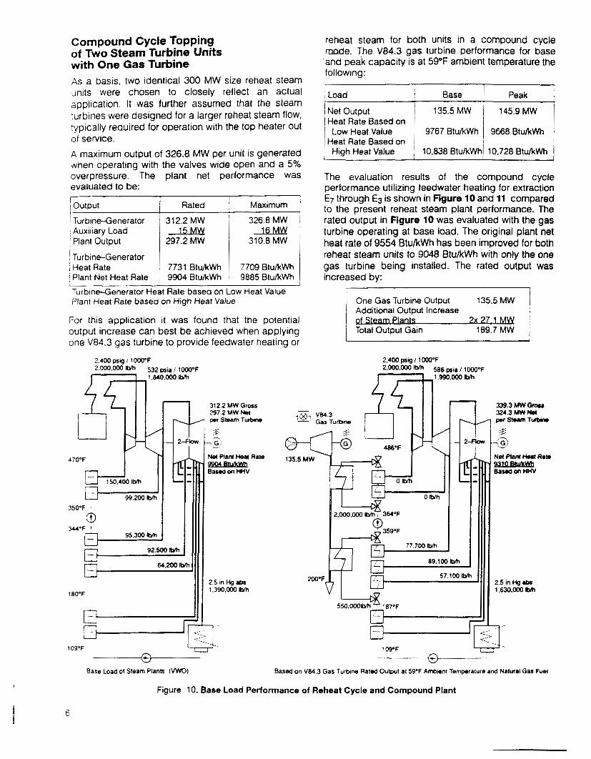
Compound Cycle Topping of Two Steam Turbine Units with One Gas Turbine As a basis, two identical 300 MW size reheat steam units were chosen to closely reflect an actual application. It was further assumed that the steam turbines were designed for a larger reheat steam flow, typically required for operation with the top heater out of service. A maximum output of 326.8 MW per unit is generated when operatinq with the valves wide open and a 5%
I 1 Load Base Peak
High Heat Value 10,838 Btu/kWhi 10,728 BtuntWh
Low Heat Value Heat Rate Based on
~~
The evaluation results of the compound cycle performance utilizing feedwater heating for extraction E7 through E3 is shown in Figure 10 and 11 compared to the present reheat steam plant performance. The rated output in Figure 10 was evaluated with the gas turbine operating at base load. The original plant net heat rate of 9554 Btu/kWh has been improved for both reheat steam units to 9048 Btu/kWh with only the one gas turbine being installed. The rated output was increased by:
One Gas Turbine Output Additional Output Increase
Total Output Gain 189.7 MW
135.5 MW
- overpressure. The evaluated to be:
plant net performance was
Rated 1 Maximum I 312.2 MW 326.8 MW
297.2 MW 1 310.8 MW
7731 Btu/kWh 1 7709 BtuIkWh 9904 BtukWh 9885 BtuIkWh
LLsAw 2 L M Y l
- Output _ _ ~ Turbine-Generator Auxiliary Load Planl Output
TurbineGenerator Heat Rate Planl Net Heat Rate
TurbineGenerator Heal Rate based on Low Heat Value Plant Heat Rate based on High Heat Value
For this application it was found that the potential output increase can best be achieved when applying one \/84.3 gas turbine to provide feedwater heating or
339.3 Mw Gnwr 324.3 Mw N* per Sturn Turbiin
%
31
per Steam Turtnne
-@ T9 486°F v-\ - I 9-84 b e t i on HHV
2.5 in Hg ahs 1.390.000 Ibm
J 99.200 Ibm
350'F
(3 344°F '
95.300 IMl
2OO'F, 2.5 in Hg .bs 1.630.000 ltJh 180°F
Base Load 01 Steam Plants (VWO) Based on V84.3 Gas Turbine Rated Output a1 59'F Ambent Temperature and Natural Gas Fuel
Figure 10. Base Load Performance of Reheat Cycle and Compound Plant
- 0

2.520 DSICI 1 1OOO'F
' output MW
I Output Increase j MW 1 %
Btu/kWh Improvement
I Btu/kWh 1 % I
310.8 M W N.1 per Seam T U ~ ~ I M
769.6 8426 825.1
Base 73.0 55.5 Base 1 9 5 7.2
10017 9147 9269
Base 8 70 748 Base , 8 7 7 5
101.3oolMl w
1W'F , h
v Maximum Capauty of Steam Plants (VWO + 5% OP)
2.520 psg I 10oo°F
355.6 MW Orosr 339.6 M W W per slum Turbule
Based on V84 3 Gas Turtnne Peak Load a1 5PF Temperature and Natural Gas F11.l
Figure 11. Peak Load Performance of Reheat Cycle and Compound Cycle Plant
The maximum plant output increased, when operating the gas turbine at peak-load capacity shown in Figure 11 with a heat rate level of 9008 Btu/kWh, as f 01 Io w s :
~ One Gas Turbine Output 145 9 MW ' Additional Output Increase I
nts 3x ?W Total Output Gain 203.5 MW
The maximum performance for adding one V84.3 gas turbine-generator as a simple cycle peaking unit to the system compared to building a completely new combined cycle plant or a compound cycle arrangements IS shown in the following three eauations:
Steam Turbine Plant 2x 310.8 MW 9885 Btu/kWh Gas Turbine Plant lx 148 MW 10570 Rtu/kW h Total Plant 769.6 MW 10017 Btu/kWh
Addition of a Simple Cycle V84.3 Plant
Steam Turbine Plant 2x 310.8 MW 9885 Btu/kWh
Total Plant 842.6 MW 9147 BtuIkWh
Addition of a Combined Cycle V84.3 Plant
Gas Turbine Plant lx 271 MW -
Steam Turbine Plant 2x 339 6 MW 8955 BtukWh Gas Turbine Plant h 145.9
9269 BtukWh Total Plant 825 1 MW
The higher gas turbine output for the simple cycle application is the result of smaller outlet pressure losses.
Summarizing these results leads to the following improvements of performance for adding combined cycle or compound cycle units versus adding a simple cycle gas turbine unit:
! Total Plant Simple Combined Compound I Net Performance 1 Cycle j Cycle 1 Cycle
Addition of a Compound Cycle V84.3 Plant
I
I I I I I I I
7

The smaller increase in output and decrease in heat rate for the compound cycle versus the combined cycle is mainly a result of increased losses in the steam turbines LP sections. By replacing these parts of the existing steam turbines the output gain and heat rate performance for the compound cycle can be further improved.
For selecting an optimal repowering concept for this uniclue compound cycle application, we investigated this and three more cycle concepts.
Steam Plant Output
Total Output
Auxiliary Power Plant Net Output
Gas Turbine Output
Alternative I Feedwater Heating for Extractions E7 through E3
Reheat Plant ComDound Cvc le
2x 355.6 MW l.x2caw
653.6 MW 857.1 MW
7x 16 MW 7x 1 6 M b 621.6 MW 825.1 MW
2x 326.8 MW
The arrangement provides this capacity increase at an attractive heat rate improvement of 616 Btu/kWh or 6.2%. This improvement over the reheat steam plant performance is very attractive and is a result of optimal utilization of the gas turbine exhaust energy at a high energy level. Full--load operation of the gas turbine and partial-load operation of the steam plants might be limited by the final feedwater temperature reaching a level at which boiling in the reheat steam boilers' economizers could occur. For controlling such operational modes the heat exchanger is of a special design, shown in Figure 12, providing extremely high operating flexibility. The dual-duct design of the heat recovery heat exchanger permits any mode of operation of the one gas turbine and two steam plants. An auxiliary stack is
8
provided to operate the gas turbine without the steam plants, since flue gas flows are controlled by three
' multipl&ouver dampers. The two dampers upstream of the heat exchangers for the two steam plants provide independent flow and consequently temperature control for each of these units. With this arrangement operating the gas turbine and only one steam plant is possible. This system also allows start-up of one unit with the other steam plant already in full operation. The detailed design of the heat exchanger for feedwater preheating is illustrated in Figure 13. The gas turbine exhaust enters at first the single gas turbine stack. From there the gas flow is equally split into channels leading to two independent HP and LP feedwater heating tube bundles. This duakhannel arrangement has been chosen to operate the two steam plants independently. This design concept has been developed to provide the highest degrees of operating flexibility. The gas flows are controlled by louver dampers. Two rows of louvers are installed in the gas turbine auxiliary stack to minimize leakage losses during operation of the HP and LP feedwater heat exchangers. Pressurizing the area between these two rows of louvers eliminates any
Turbine II m I
V84.3 Gaa @-G--& Turbine I
Figure 12. Alternative I - Feedwater Heating E7, through E3

Top View
I I
7---- Elcvatlon-.- 125 '0"
Dischsrg.
-\-- -I
~
HP and LP F a u h 8 t . r
I 11 1'-7" U
Side View
Figure 13. Heat Exchanger for Feedwater Preheating
leakage losses. In front of each heat exchanger section is a single row louver damper installed to control independently the gas flow to the HP and LP feedwater heat exchangers. Operating experience with louver dampers in Europe have been very positive. Modulating the three dampers in the auxiliary stack and up stream of the two heat exchanger
Gas Turbine Air Filtom
I
~ 7' 1 GasTuhim Transformas:
Main Auxiliary I
sections is the proper sequence permits controlling operations of: - . only the gas turbine
the gas turbine with one steam turbine unit the gas turbine with two steam turbine units transfer from and to any of these operation modes start-up to all these operating conditions
The gas turbine stack for the V84.3 gas turbine is 18 feet and the two discharge stacks of the heat exchanger sections are 13 feet in diameter. Operation with one steam plant requires partial opening of the auxiliary stack to optimize maximal feedwater heat supply to this unit and a minimum of pressure losses at the gas turbine exhaust.
The arrangement of the heat exchanger with a V84.3 advanced gas turbine is illustrated in Figure 14. The heat exchanger with its over all length of 111'7" is connected to the axial diffuser of the gas turbine. The overall length of the V84.3 gas turbine with a 165 MVA generator is 75'7". Adding the diffuser length of 37' results in a total length of 224'2" for the entire gas turbine/heat exchanger plant.
As illustrated the advanced V84.3 gas turbines' two combustion chambers are horizontally arranged. The gas turbine air intake at the generator side is extended to the air filters which are mounted above the air-cooled generators. The turbine inclosure width is approximately 64 feet which provides space for auxiliaries and internal maintenance work. The V84.3 gas turbine features 2x 6 hybrid burners to provide low NO, emission without steam or water injections in a premix burning m ~ d e [ ~ ~ * ] . For operation with fuel oil or for power augmentation steam or water injection is provided.
Auxiliry
Stack \-
DiScharg. Stacks
\ -
I I I I
. - I
Figure 14. V84.3 Gas Tuhindenerator with Heat Exchanger for Feedwater Preheating
9

Alternative 11 Feedwater Heating for Extractions E7 through €1
This cycle shown in Figure 15, provides the following increase in maximum plant output at a heat rate improvement of 389 Btu/kWh or 3.9%:
- ! Reheat Plant Steam Plant Output 2x 326.8 MW Gas Turbine Output 0 MU Total Output 653.6 MW
Auxiliary Power u Plant Net Output 621.6 MW
Comoound Cvcle
2x 345.9 MW l x 145&.b&Y
837.7 MW
2xJuYlu 805.7 MW
Plant Net Output Increase
Reheat Plant ComDound Cv&
Steam Plant Output 2x 326.8 MW 2x 353.5 MW Gas Turbine Output 0 MW Lx 1 4 W Total Output 653.6 MW 852.9 MW
818.9 MW Auxiliary Power Plant Net Output 621.6 MW
Plant Net Output Increase 197.3MW
2 u L M u Au!a!m
I 184.1 MW 1
This arrangement with a dual-duct heat exchanger is similar to alternative I , but provides partial feedwater heating for all seven feedwater heaters. At maximum power plant load, about 57% of the feedwater is preheated by the gas turbine exhaust energy and the rernaining 43% by the steam extractions from the
Condonuto Pump
Plant Not Output m5.7 Mw Pbnt N*W tiomt &to wee B~WICWII
Figure 15. Alternative I1 - Feedwater Heating €7 through El
steam turbines through their feedwater heaters. This arrangement is not as efficient since the gas turbine discharge energy is not utilized at an elevated level and 109’F condensate is heated by 200’F flue gas. To avoid corrosion in the heat exchangers’ discharge section, recirculation pumps must be installed for raising the condensate inlet temperature. Partial-load operation of the steam plants without increasing the final feedwater temperature can be performed by simply increasing the feedwater flow through the feed- water heat exchangers.
Alternative 111
Operation without the top feedwater heater in service basically results in an increase in reheat steam flow and pressure. Instead of utilizing the gas turbine exhaust for feedwater heating, this alternative generates hot reheat steam in the heat recovery steam generator which is then admitted into the reheat steam systems of the steam plants, as illustrated in Figure 16. The high gas turbine exhaust temperature provides steam with about 1000°F. The compound cycle maximum output increase at an improved heat rate level of 623 Btu/kWh (6.3%) is:
-.
Hot Reheat Steam Supply
10
-

Reheat Turbine II -1
Reheat Plant
2x 326.8 M W
653.6 MW
Au!iMu 621.6 MW
236.mOLvh
Reheat
2x 354.8MW J J A A L u Y w
821.5 MW 1
, S l r m , 6- I
Figure 16. Alternative 111 - Reheat Steam Supply
supply for the HRSG and the two reheat steam plants. This control concept also permits independent operation of the two reheat steam units. Since no auxiliary stack is provided gas turbine operation is only possible with at least one steam plant in operation or at partial load with a reduced exhaust temperature. Steam bypass systems are supplied to provide operating flexibility like gas turbine start-up with the steam units operating at full load.
Alternative IV Hot Reheat Steam Supply and Feedwater Heating for Extraction E5 through E3
This compound cycle arrangement of a HRSG with feedwater heating provides a greater performance increase than alternative I l l with a heat rate improvement of 655 Btu/kWh (6.6%) and the following maximum output:
Steam Plant Output Gas Turbine Output Total Output
Auxiliary Power Plant Net Output
Plant Net Output Increase 199.9MW 1
Figure 17. Heat Energy - Temperature Diagram of Aitemativo Ill
As illustrated in Figure 18, feedwater preheating is provided for extraction E5, and E3 from the low temperature section of the HRSG. The steam generation section of the HRSG receives feedwater from the steam plants’ boiler feedwater pumps. The feedwater and reheat steam flows from and to the two steam plants are controlled as in alternative I l l .
Besides best performance, the operating flexibility is compatible to alternative Ill, permitting full-load gas
Reheat Turbine II
Reheat
El- * C- Rnnp
821.5 MW 9230 ewkm
PImt Mol Ou@ul PImt k w H..1 Rata
Figure 18. Alternative IV - Reheat Steam Supply plua Feedwater Heating E5 through E3
11

turbine operation with oniv one steam plant in operation. In cases where the gas turbine to steam turbine output ratio is larger or the reheat pressure is lower, this cycle would become even more efficient because of the increased reheat steam produced at a high energy level.
7
Present Reheat Steam Plants
Gas Turbine Output MW I MW 1 2x3268
I-
Evaluation of Alternatives I through IV
Alternative I Alternative Alternative Alternative
2x3556 2x3459 1 2x3535 2x3548
I 1 Ill IV I 1459 i IX 1459 1 IX 1459 1x1459
All four alternatives are valid options to be utilized for cornpound cycle repowering. The two feedwater heat exchanger options seem to be easier to integrate into existing plants, since only feedwater piping connects the gas turbine plant with the steam plants. This pipes' pressure and heat losses are not a major concern. On the other hand the heat recovery steam generator options provide a slightly better performance improvement. At first it was thought that the feedwater heat exchangers should be much less expensive than the HRSG's, however, a price comparison considering the use of auxiliary stacks and dampers for the feedwater heat exchanger options raise their cost.
The feedwater heat exchange options provide greater operating flexibility. which is especially important i f
load cycling and two-shift operation is considered.
In regard to thermal efficiency alternative IV is the best solution, whereas the largest output increase IS
achieved with alternative I , as listed in Figure 19. The larger output increase of alternative I is a result of the increased reheat steam production in the steam plants. The plant net outputs and net heat rates of the various alternatives reveal differences which must be part of a proper evaluation of topping options.
The gas turbine performance IS influenced by uifferences in outlet pressure loss of the heat exchangers and HRSG's, however, all calculations were performed with 12 inch H20 because it was assumed that a lower pressure drop in the heat axcmangers might be compensated by the use of the auxiliary stack and dampers for these alternatives.
A 165 MVA air-cooled generator has been selected for all alternatives. However, a larger air-cooled
I Plant Net Heat Rate I % Base
L_
generator can be provided for operating at a lower gower factor, in case the maximum steam turbine genera-tor capacity is limited and additional reactive power IS needed. Presently air-cooled generator frame sizes up to 260 MVA are available.
The steam turbine-generators were originally designed for the following potential flows.
1 Main Steam Reheat Steam Exhaust Steam I i 2,100,000 Ib/h 2.100.000 Ib/h 1,600,OOO Ib/h 1
1 _ _ _ _ _
6 2 3 9 6 3 1 6 6 1
The maximum steam turbine output in a compound cycle operating mode of 355.6 MW required the following flows (see also Figure 11):
i Reheat Steam Exhaust Steam i $ ~ ~ , ~ ~ ? l ~ / h 2,090,000 Ib/h 1,710,OOo Ib/h
The exhaust steam flow is the only one which has been increased above its original value. But this increase - f only 7% can generally be handled if the steam turbines are not backend loaded or the LP blading is designed for a low mass flow limit. In this case the LP turbine steam path can be replaced with an advanced design to provide improved performance and a backend loading up to 18,000 lb/ft2hig lo]. Such an example is illustrated in Figure 20 as alternative IA revealing an additional performance improvement of 16 MW over alternative I for both steam turbines.
Applying a combined cycle instead of a simple cycle unit reduces the heat rate level of the entire plant by (1.3% + 7.5%) 8.8%. This result is based on a combined cycle plant heat rate of 7070 Btu/kWh at HHV and 6370 Btu/kWh at LHV, which accounts for a 53.6% combined cycle plant efficiency. The improvement with the compouna cycle alternative I is 7.5% and can be even raised to 9.3% by adding advanced LP turbine replacements. A similar, however, somewhat smaller improvement can be expected for the combined cycle option when supplying additional LP turbine replacements.

Conclusion
Total Plant r Net Performance
Combined cycle plants with heat recovery steam generators and with fully-fired steam generators as well as compound cycle plants are depending on the circumstance valid alternatives for repowering Or top p i n g a p p I ica t ions. When summarizing our find in g s for the repowering of two 300 MW steam plants with one advanced gas turbine, the comparison Of
performance versus the two present reheat units are revealed in Figure 19 based on the maximum total power plant net output. Alternative I provides the largest output increase of 32.7% and alternative IV achieves the best heat rate decrease of 6.6%. It should be noted that the evaluation of cycle performance differences is based on a constant main Steam flow. A similar study based on constant thermal caiiacity of the steam plant's steam generators would show a relatively better performance for alternatives I I I and IV with HRSG's.
Reheat 1 Simple Combined Compound Cycle Cycle
Plant I Cycle HRSG Alt I 1 Alt IA
I
Adding a simple cycle gas turbine plant to an existing steam plant increases the weighted heat rate when operating at full-load, however, the total output is increased by the peaking capacity of the gas turbine (see Figure 20). Adding a combined cycle plant with a heat recovery steam generator provides the best performance in heat rate and output. Depending on the specific plant conditions, similar results can be achieved with a fully-fired topping arrangement. Utilizing a compound cycle arrangement provides a somewhat lower output and worse heat rate compared to 1:he combined cycle alternative. However, output and heat rate performance of this compound cycle plaiit can be improved by replacing the LP turbines. The utilization of advanced LP turbine sections provides a heat rate and output improvement in the
I 1
148 22 1 203.5 MW 1 Base 1
Base 23.8 1 35 6 32.7 He at Rate
B t u/kWh
the compound cycle plant reveals as slightly lower output but better heat rate than the combined cycle
with heat recovery steam generator.
219.5 35.3
9093
In regard to emission discharge the specific emission per generated kWh is reduced for all alternatives because the gas turbine with its hybrid burners provides a low NO, emission in the range of 25 ppm without steam or water injections. An even larger improvement can be achieved with a fully-fired combined cycle plant since the hot exhaust gas from the gas turbine is used for secondary combustion in the reheat steam generators. At the Eemscentrale plant this concept, in combination with an exchange of the burners in the steam generators, lead to a reduction of the NO, emission from 400-500 ppm before repowering to 100-150 ppm after the gas turbine was topped onto the existing 600 MW steam plant.
In cases where large relatively new existing steam plants reveal a potential for uprating, the compound cycle application is an attractive option. This eliminates the need for installing a new steam turbine plant with its auxiliary systems like condenser and cooling water supply as well as avoiding a major rebuild of the existing steam generators.
Without modifying the steam turbine flow path, increasing the capacityof existing steam turbinesmight be limited. When considering replacement of steam turbine sections, the compound cycle concept can generate maximum additional output at a very attractive heat rate level. Since an existing steam plant is utilized, the specific cost for such compound cycle topping can be as low as the expense of building a simple cycle gas turbine plant.
range of 2 to 3%. With this addition the performance of
~
+ "Worse Heat Rate"
Figure 20. Performance of Various Cycle Arrangements
13

I _ . Acknowledgement Special thanks is given to Mr Jerry Saddler of NooteVEriksen who supported a feasibility study, which lead to the aesign of a dual-duct heat exchanger with independent flue gas flow controls. A similar design as illustrated in F l y r e 13 can also be utilized as a heat recovery steam generator for two inaependent steam supply systems.
References ['I Maghon. H.. Bergmann, D., Bruckner. H.,
Kriesten, W., and Termuehlen, H. "Combined Cycle Power Plants for Load Cycling Duties" American Power Conference, Chicago, IL April 1989
[*I Kreutzer, A., Ganzer, W., and Termuehlen, H., "Gas and Coal-Fired Combined Cycle Plants" American Power Conference, Chicago, IL April 1986
[31 Denizci, H., and Hamann, B., "Design and Operation of Ambarli combined Cycle Power Plant" AEIC, Committee on Power Generation, September 1991
1'1 IMaghon, H., Kreutzer, A., and Termuehlen, H., 'The V84 Gas Turbine Designed for Base-Load ;and Peaking Duty" American Power Conference Chicago, IL April 1988
151 Maghon, H., Schulenburg, T., Laakkonen, M., Froehlich, G., and Termuehlen, H., "Full-Load Testing of the Advanced V64.3 Gas Turbine" American Power Conference, Chicago, IL April 'I991
[61 Bruckner, H., Finckh, and H., Veenema, J., "Topping the Groningen Steam Turbine Plant with a Gas Turbine" ASME 87-GT-38
Becker, J., Maghon, H., Kugler, H., Schellhorn, L., and Termuehlen, H., "Gas Turbine Operating Performance and Considerations for Combined Cycle Conversion at Hay Road Power Station" American Power Conference, Chicago, IL, April 1990
Maghon, H., Berenbrink, P., Termuehlen, H., and Gartner, G., "Progress in NO, and Co Emission Reduction of Gas Turbines" ASME, Boston, October 1990
L91 Jacobsen, G., Oeynhausen, H., and Termuehlen, H., "Advanced LP Turbine Installation at 1300 MW Nuclear Power Station Unterweser" American Power Conference April 1991
['OIJansen, M., Pfeiffer, R., and Termuehlen, H., "Advanced LP Turbine Blade Design" ASME, PWR-Vol. #lo, 1990
14

SIEMENS
Power Generation Group KWU Erlangen. Germany
Siemens Power Corporation Bradenton. Florida
Prinled in U S A