— performance data — unit dimension … 62d series units are available in dedicated vertical or...
TRANSCRIPT

Form 62D-3SB Replaces: 62D-2SB
62D-3SB
Printed in U.S.A. 10-11 Catalog No. 04-51620003-01
© Copyright 2011 Carrier Corporation • Syracuse, New York 13221
62DA,DB,DC,DD,DE,DF07-38
DEDICATED VERTICAL OR HORIZONTAL 100% OUTDOOR AIR UNIT
— PERFORMANCE DATA— UNIT DIMENSION PRINTS— ACCESSORY DIMENSION PRINTS

2
Date: Supersedes:62DA,DB,DC,DD,DE,DF07-38DEDICATED VERTICAL OR
HORIZONTAL 100% OUTDOORAIR UNIT
62DA,DB,DC,DD,DE,DF
Rev.:-3SB
JOB NAME: LOCATION:
BUYER: BUYER P.O. # CARRIER #
UNIT NUMBER: MODEL NUMBER:
PERFORMANCE DATA CERTIFIED BY: DATE:
DESCRIPTION
All Carrier 62DA, DB, DC, DD, DE, DF dedicated outdoor air products are pre-wired, charged withR-410A, and tested in both cooling and heating modes at the factory. All 62DA, DB, DC, DD, DE ,DF units fea-ture an industrial grade cabinet with fully hinged access panels. Superior supply fan performance with up to3.5 in. wg external static pressure is standard.
The 62D Series units are available in dedicated vertical or horizontal supply configurations. The62DC,DD,DE,DF units are also available with an energy recovery wheel or exhaust. A wide variety of heatingoptions are available. All 62D Series units come standard with microprocessor control.
STANDARD UNIT — FEATURES
PERFORMANCE FEATURESPuron® HFC refrigerant (R-410A). High-efficiency scroll compressors.Thermostatic expansion valve (TXV) refrigerant metering device foreach circuit.Two-stage cooling on sizes 07, 08, 09 units, three or more stages onsizes 12 to 38.Hot gas bypass.Cooling operation range up to 115 F ambient and down to 35 F ambient.24-volt control circuit.Rubber fan vibration isolators.Double wall design.Sloped, insulated, stainless steel condensate pan.Two-inch disposable-type air filters (optional 4-in. available).Fixed speed belt-type blower drive.High-efficiency motors meet EISA (5 HP and larger).Two-position outside-air damper is standard, on 100% OA units capa-ble of admitting 100% outdoor air during fan operation, closed whenthe fan is off.Modulating economizer is standard on recirculating units.Rated in accordance with AHRI Standard 210 or 360.Tested in accordance with UL Standard 1995.Listed by ETL and ETL, Canada.Microprocessor control with:• Occupancy schedule• Password protection• Service diagnostics• Alarms and alarm history• Short-cycle compressor protection• Support of communication with BACnet* and Modbus†
protocols• Remote start/stop capability
MAINTENANCE FEATURESLarge hinged service access doors.Slide out fan system.INSTALLATION FEATURESSingle point electrical service entry, through unit bottom or side.Rigging openings in base rail.RELIABILITY FEATURESDual electrically and mechanically independent refrigeration circuits(Sizes 12 to 38).Crankcase heaters are standard on all models.Compressor protection includes high and low pressure switches.Freeze protection.Liquid line filter driers.Circuit breaker protection for all power components.Cabinet made of pre-painted, galvanized steel with baked enamel fin-ish, which meets ASTM B117 salt spray resistance.Condenser-fan motors are open drip proof, with internal protection.GAS HEATING SYSTEM FEATURESStainless steel heat exchanger.Induced draft combination for safety and reliability.Two-stage gas valves with redundant 100% shutoff.Direct spark ignition.STANDARD WARRANTYStandard one-year warranty.Five-year non pro-rated warranty on heat exchanger.
* Sponsored by ASHRAE (American Society of Heating, Refrigerating, and Air Conditioning Engineers).† Registered trademark of Schneider Electric.

3
PERFORMANCE DATA
Supply Air _____________________ cfm ________________ ESPExhaust Air ____________________ cfm ________________ ESP
COOLING COILEntering Air ____________________ db F _______________wb FTotal Capacity _______________________________________BtuhSensible Capacity _____________________________________BtuhLatent Capacity_______________________________________BtuhLeaving Air ____________________ db F _______________wb FLiquid Subcooling Circuits _________________________________Liquid Subcooling Rise (Max) _____________________________FLeaving Subcooling Coil Temperature ____________________ db FHot Gas Reheat Circuits ___________________________________Hot Gas Reheat Capacity _______________________________BtuhHot Gas Reheat Rise (Max) _______________________________ FHot Gas Reheat Leaving Air Temperature __________________ db FUnit Power Consumption ________________________________kWUnit Efficiency _______________________________________ EER
OPTIONAL ENERGY CONSERVATION WHEEL
SUMMER CONDITIONSEntering Air ____________________ db F _______________wb FReturn Air _____________________ db F _______________wb FTotal Capacity _______________________________________BtuhSensible Capacity _____________________________________Btuh
WINTER CONDITIONSEntering Air ____________________ db F _______________wb FReturn Air _____________________ db F _______________wb FTotal Capacity _______________________________________BtuhSensible Capacity _____________________________________Btuh
OPTIONAL GAS HEATInput _______________________________________________BtuhOutput _____________________________________________BtuhTotal Temperature Rise __________________________________ FEntering-Air Temperature ________________________________ FLeaving-Air Temperature _________________________________ F
OPTIONAL ELECTRIC HEATTotal Heating Capacity __________________________________kWHeat Output _________________________________________BtuhTotal Temperature Rise __________________________________ FEntering-Air Temperature ________________________________ FLeaving-Air Temperature _________________________________ F
OPTIONAL HOT WATER HEATING COILFluid Type ______________________________________________Flow ______________________________________________ GpmTotal Heating Capacity _________________________________BtuhEntering Water Temperature ______________________________ FLeaving Water Temperature _______________________________ FTotal Temperature Rise __________________________________ FEntering-Air Temperature ________________________________ FLeaving-Air Temperature _________________________________ F
OPTIONAL STEAM HEATING COILSteam Pressure ________________________________________ psiCondensate Flow _____________________________________ lb/hrTotal Heating Capacity _________________________________BtuhTotal Temperature Rise __________________________________ FEntering-Air Temperature ________________________________ FLeaving-Air Temperature _________________________________ F
ELECTRICAL DATA
Power Supply to Unit ___________ Volts ________________ Phase _________ Hz
Minimum Circuit Amps ______________ Maximum Overcurrent Protection _______________
SUBMITTAL DATA
Job Name ___________________________________________________________
Architect ____________________________________________________________
Engineer ____________________________________________________________
Contractor ___________________________________________________________
Unit Designation ______________________________________________________

4
OPTIONS AND ACCESSORIES
FACTORY-INSTALLED OPTIONS
Gas Heat Gas Heat with Space Temperature Override Electric Heat Hot Water Heating Coil Steam Heating Coil Energy Conservation Wheel Energy Conservation Wheel with VFD Defrost Control Energy Conservation Wheel with Return Air Bypass Filter Status Switch Phase/Voltage Monitor with Energy Management Relay Firestat VFD on IFM VFD on PE motor Convenience Outlet Disconnect Switch
Hot Gas Reheat Coil Liquid Subcooling Coil Coated Coils 4-in. MERV 8 Filters 4-in. MERV 11 Filters 4-in. MERV 15 Filters 2-in. Metal Mesh Filters Backward Inclined Supply Fan Forward Curved Exhaust Fan Backward Curve Fan Airfoil Fan LonWorks* Communication Digital Compressor Return Air Smoke Detector CO2 Sensor
FIELD-INSTALLED ACCESSORIES Roof Curb (14 in.) Roof Curb (24 in.)
BACview Handheld Keypad Display
OTHER SPECIAL ITEMS
__________________________________________________________________________________________________________________
__________________________________________________________________________________________________________________
__________________________________________________________________________________________________________________
__________________________________________________________________________________________________________________
__________________________________________________________________________________________________________________
__________________________________________________________________________________________________________________
__________________________________________________________________________________________________________________
__________________________________________________________________________________________________________________
__________________________________________________________________________________________________________________
__________________________________________________________________________________________________________________
* Registered trademark of Echelon Corporation.

5
CU
T A
LON
G D
OT
TE
D L
INE
CU
T A
LON
G D
OT
TE
D L
INE
UNIT DIMENSION PRINT — 62DA,DB07-09 STANDARD UNIT
NOTES:1. Carrier recommends a minimum of 24 to
36-in. of service clearance on all sides ofunit except for the control panel side,which should have at least 48-in. clear-ance. Top should be unobstructed.
2. Dimensions are in inches.a62-564
TOP VIEW
FRONT VIEW
38 1/2
57 1/2
82 1/2
38 1/4
62
8
97 1/814 5/8
FILTER ACCESS
OUTSIDE AIRINTAKE HOOD
CONTROL PANELSUPPLY FAN
CONDENSATE DRAIN PAN
96
SU
PP
LY
720
36
3 1/2
1 TYP.
4
39 3/4 2 1/2
6 1/2
15 1/2
POWER THROUGH THE CURB
GAS INLET
SIDE VIEW(HORIZONTAL SUPPLY)
36
5
520 16 1/2
32
6
SUPPLY RETURN
TOP VIEW
FRONT VIEW
SUPPLY FANFILTER ACCESS
CONTROL PANEL
OUTSIDE AIR
INTAKE HOOD
CONDENSATE DRAIN PAN
POWER THROUGH THE CURB
7
15 1/2
3 1/2
36
838 1/4
1TYP.
30 1/4 20
38 1/2
57 1/2
96
82 1/2
4
6 1/2
2 1/2 39 3/4
62
106 3/4
9 7/8
24 1/8
3 1/2
20
36
15 1/2
GAS INLET
SIDE VIEW(HORIZONTAL SUPPLY)
36
5
520 16 1/2
32
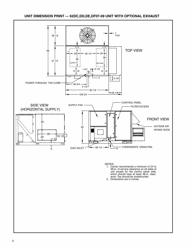
UNIT DIMENSION PRINT — 62DC,DD,DE,DF07-09 UNIT WITH OPTIONAL EXHAUST
NOTES:1. Carrier recommends a minimum of 24 to
36-in. of service clearance on all sides ofunit except for the control panel side,which should have at least 48-in. clear-ance. Top should be unobstructed.
2. Dimensions are in inches.
a62-565

7
CU
T A
LON
G D
OT
TE
D L
INE
CU
T A
LON
G D
OT
TE
D L
INE
S UPPLY FAN
FILTER ACCESS
CONTROL PANEL
SUPPLY RETURN
TOP VIEW
FRONT VIEW
OUTSIDE AIRINTAKE HOOD
720
3 1/2
36
838 1/4 CONDENSATEDRAIN PAN
38 1/2
57 1/ 2
104 5/8
30 1/4
24 1/8
9 7/8
128 3/4
96
EXHAUST
1 TYP
62
3 7/8
3 1/2
20
36
15 1/2 15 1/26 1/2
42 1/2POWER THROUGH THE CURB
39 3/4
GAS INLET
SIDE VIEW(HORIZONTAL SUPPLY)
36
5
520
16 1/2
32
UNIT DIMENSION PRINT — 62DC,DD,DE,DF07-09 UNITWITH OPTIONAL ENERGY CONSERVATION WHEEL
NOTES:1. Carrier recommends a minimum of 24 to
36-in. of service clearance on all sides ofunit except for the control panel side,which should have at least 48-in. clear-ance. Top should be unobstructed.
2. Dimensions are in inches.a62-566

8
TOP VIEW
FRONT VIEW
38 1/2
57 1/2
82 1/2
97 1/8
38 1/4
62
8
14 5/8
FILTER ACCESS
OUTSIDE AIRINTAKE HOOD
CONTROL PANELSUPPLY FAN
CONDENSATE DRAIN PAN
9620
36
4
6 1/2
SUPPLY
15 1/2
1 TYP.
3 1/2
7
POWER THROUGH THE CURB
2 1/239 3/4
GAS INLET
SIDE VIEW(HORIZONTAL SUPPLY)
36
5
520 16 1/2
32
UNIT DIMENSION PRINT — 62DA,DB12-20 STANDARD UNIT
NOTES:1. Carrier recommends a minimum of 24 to
36-in. of service clearance on all sides ofunit except for the control panel side,which should have at least 48-in. clear-ance. Top should be unobstructed.
2. Dimensions are in inches.
a62-567

9
CU
T A
LON
G D
OT
TE
D L
INE
CU
T A
LON
G D
OT
TE
D L
INE
SUPPLY FAN FILTER ACCESS
CONTROL PANEL
TOP VIEW
FRONT VIEW
OUTSIDE AIRINTAKE HOOD
838 1/4 CONDENSATEDRAIN PAN
EXHAUST
38 1/2
57 1/2
96
9 7/8
24 1/882 1/2
106 3/4
3 1/2
62
1 TYP.
4
2 1/2POWER THROUGH THE CURB
6 1/215 1/2
39 3/4
7
3 1/2
20 2030 1/4
3636
15 1/2
SUPPLY RETURN
GAS INLET
SIDE VIEW(HORIZONTAL SUPPLY)
36
5
520
16 1/2
32
UNIT DIMENSION PRINT — 62DC,DD,DE,DF12-20 UNIT WITH OPTIONAL EXHAUST
NOTES:1. Carrier recommends a minimum of 24 to
36-in. of service clearance on all sides ofunit except for the control panel side,which should have at least 48-in. clear-ance. Top should be unobstructed.
2. Dimensions are in inches.
a62-568

10
8
62
TOP VIEW
FRONT VIEW
OUTSIDE AIRINTAKE HOOD
EXHAUST
FILTER ACCESS
CONTROL PANELSUPPLY FAN
38 1/2
57 1/2
4 3/8
38 1/4
104 5/8
128 3/4
9 7/8
24 1/8
96
CONDENSATE DRAIN PAN
30 1/4
1 TYP.7
20 20
36 36
3 1/2 3 1/2
3 7/8
2 1/24
15 1/26 1/2
15 1/2
POWER THROUGH THE CURB
39 3/4
SUPPLY RETURN
GAS INLET
SIDE VIEW(HORIZONTAL SUPPLY)
36
5
520 16 1/2
32
UNIT DIMENSION PRINT — 62DC,DD,DE,DF12-20 UNITWITH OPTIONAL ENERGY CONSERVATION WHEEL
NOTES:1. Carrier recommends a minimum of 24 to
36-in. of service clearance on all sides ofunit except for the control panel side,which should have at least 48-in. clear-ance. Top should be unobstructed.
2. Dimensions are in inches.
a62-569

11
CU
T A
LON
G D
OT
TE
D L
INE
CU
T A
LON
G D
OT
TE
D L
INE
TOP VIEW
FRONT VIEW
33 3/4
62 1/4
131
18 1/2
112 9/16
62 5/8
83
8
2 13/16
FILTER ACCESS
OUTSIDE AIRINTAKE HOOD
CONTROL PANELSUPPLY FAN
CONDENSATE DRAIN PAN
96
10 7/8
1 TYP.
30
40
SUPPLY
17 6 1/262 3/8
4POWER THROUGH THE CURB
GAS INLET
GAS INLET
SIDE VIEW(HORIZONTAL SUPPLY)
40 1/2
30 1/218 1/2
4 1/2
43 1/2
4 1/2
UNIT DIMENSION PRINT — 62DA,DB22-38 STANDARD UNIT
NOTES:1. Carrier recommends a minimum of 24 to
36-in. of service clearance on all sides ofunit except for the control panel side,which should have at least 48-in. clear-ance. Top should be unobstructed.
2. Dimensions are in inches.a62-570

12
EXHAUST
FILTER ACCESS
TOP VIEW
FR ONT VIEW
OUTSIDE AIRINTAKE HOOD
83
CONDENSATEDRAIN PAN
112 1/234 1/4
146 3 /4
96
33 3/4
62 1/4
SUPPLY FANCONTROLPANEL
62 5/88
1 TYP.
10 7/8
2 7/8 4 15/16
30 24
40 50
42 1/16
SUPPLY RETURN
2 1/4POWER THROUGH THE CURB
62 3/8 176 1/2
4
4 7/8
14 3/8
GAS INLET
GAS INLET
SIDE VIEW(HORIZONTAL SUPPLY)
40 1/2
30 1/218 1/2
4 1/2
43 1/2
4 1/2
UNIT DIMENSION PRINT — 62DC,DD,DE,DF22-38 UNIT WITH OPTIONAL EXHAUST
NOTES:1. Carrier recommends a minimum of 24 to
36-in. of service clearance on all sides ofunit except for the control panel side,which should have at least 48-in. clear-ance. Top should be unobstructed.
2. Dimensions are in inches.
a62-571

13
CU
T A
LON
G D
OT
TE
D L
INE
CU
T A
LON
G D
OT
TE
D L
INE
TOP VIEW
FRONT VIEW
33 3/4
62 1/4
136 5/8
83
62 5/88
15 3/8
34 3/16
FILTER ACCESSENERGY RECOVERY WHEEL
OUTSIDE AIRINTAKE HOOD
CONTROLPANEL
SUPPLY FAN
CONDENSATE DRAIN PAN
EXHAUST
170 3/4
96
1 TYP.
10 7/8 30
40 50
2442 1/16
4 7/83 1/4
POWER THROUGH THE CURB
174
6 1/263 1/2
SUPPLY
RETURN
2 13/16 4 15/16
GAS INLETGAS INLET
SIDE VIEW(HORIZONTAL SUPPLY)
40 1/2
30 1/218 1/2
4 1/2
43 1/2
4 1/2
UNIT DIMENSION PRINT — 62DC,DD,DE,DF22-38 UNITWITH OPTIONAL ENERGY CONSERVATION WHEEL
NOTES:1. Carrier recommends a minimum of 24 to
36-in. of service clearance on all sides ofunit except for the control panel side,which should have at least 48-in. clear-ance. Top should be unobstructed.
2. Dimensions are in inches.
A62-572
14
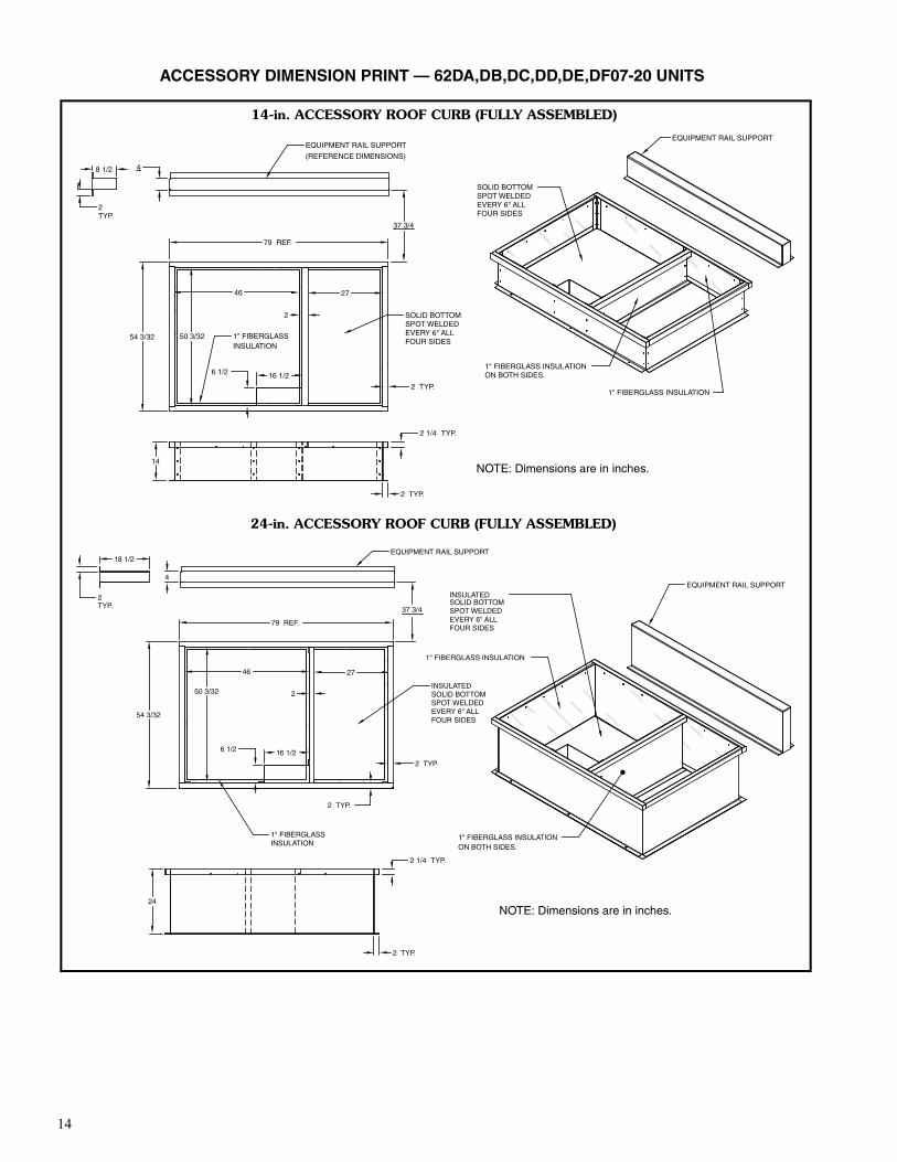
1" FIBERGLASS INSULATION
1" FIBERGLASS INSULATION
SOLID BOTTOMSPOT WELDED EVERY 6" ALL FOUR SIDES
SOLID BOTTOMSPOT WELDED EVERY 6" ALL FOUR SIDES
EQUIPMENT RAIL SUPPORT
(REFERENCE DIMENSIONS)
EQUIPMENT RAIL SUPPORT
1" FIBERGLASS INSULATIONON BOTH SIDES.
79 REF.
54 3/32
6 1/2 16 1/2
2 TYP.
2 1/4 TYP.
2
50 3/32
46 27
2 TYP.
4
14
8 1/2
2TYP.
37 3/4
1" FIBERGLASS INSULATION
1" FIBERGLASS INSULATION
INSULATEDSOLID BOTTOMSPOT WELDED EVERY 6" ALL FOUR SIDES
INSULATEDSOLID BOTTOMSPOT WELDED EVERY 6" ALL FOUR SIDES
1" FIBERGLASS INSULATIONON BOTH SIDES.
EQUIPMENT RAIL SUPPORT
EQUIPMENT RAIL SUPPORT
2 TYP.
79 REF.
6 1/2 16 1/2
2 TYP.
2 TYP.
2 1/4 TYP.
250 3/32
46 27
24
54 3/32
37 3/4
2TYP.
18 1/2
4
14-in. ACCESSORY ROOF CURB (FULLY ASSEMBLED)
24-in. ACCESSORY ROOF CURB (FULLY ASSEMBLED)
a62-405
ACCESSORY DIMENSION PRINT — 62DA,DB,DC,DD,DE,DF07-20 UNITS
NOTE: Dimensions are in inches.
NOTE: Dimensions are in inches.

15
CU
T A
LON
G D
OT
TE
D L
INE
CU
T A
LON
G D
OT
TE
D L
INE
ACCESSORY DIMENSION PRINT — 62DA,DB,DC,DD,DE,DF07-20 UNITS
Curb End
UtilityChannel
Curb Side
Equipment Support (Screw 2 Parts Together)
Supply24 1/2"
36 1/2"
20 1/2"
50 1/8"
41 3/4"
74 3/4"
Return
— Gasket
Gasket
NailCounter Flashing(Field Supplied)
Roofing Felt(Field Supplied)
Cant Strip(Field Supplied)
Roofing Material(Field Supplied)
Rigid Insulation(Field Supplied)
a62-549
14-in. ACCESSORY ROOF CURB (FIELD ASSEMBLED)
24-in. ACCESSORY ROOF CURB (FIELD ASSEMBLED)
NOTE: Dimensions are in inches.
NOTE: Dimensions are in inches.
Curb End
UtilityChannel
Curb Side
Equipment Support (Screw 2 Parts Together)
Supply24 1/2"
36 1/2"
20 1/2"
50 1/8"
41 3/4"
74 3/4"
Return
— Gasket
Gasket
NailCounter Flashing(Field Supplied)
Roofing Felt(Field Supplied)
Cant Strip(Field Supplied)
Roofing Material(Field Supplied)
Rigid Insulation(Field Supplied)
A30-553

16
1" FIBERGLASS INSULATION
1" FIBERGLASS INSULATION
INSULATEDSOLID BOTTOMSPOT WELDED EVERY 6" ALL FOUR SIDES
EQUIPMENT RAIL SUPPORT
EQUIPMENT RAIL SUPPORT
1" FIBERGLASS INSULATIONON BOTH SIDES.
58 13/16
109REF.
48 55
54 13/16
16 1/2
38 1/2
6 7/162 TYP.
2 1/4 TYP.2 TYP.
2 TYP.
14
8 1/2
2TYP.
4
33
1" FIBERGLASS INSULATION
1" FIBERGLASS INSULATION
INSULATEDSOLID BOTTOMSPOT WELDED EVERY 6" ALL FOUR SIDES
INSULATEDSOLID BOTTOMSPOT WELDED EVERY 6" ALL FOUR SIDES
1" FIBERGLASS INSULATIONON BOTH SIDES.
EQUIPMENT RAIL SUPPORT
EQUIPMENT RAIL SUPPORT
58 13/16
109REF.
48 55
54 13/16
16 1/2
38 1/2
6 7/16
2 TYP.
2 1/4 TYP.
2 TYP.
2 TYP.
24
18 1/2
2TYP.
4
33
14-in. ACCESSORY ROOF CURB (FULLY ASSEMBLED)
24-in. ACCESSORY ROOF CURB (FULLY ASSEMBLED)
a62-406
ACCESSORY DIMENSION PRINT — 62DA,DB,DC,DD,DE,DF22-38 UNITS
NOTE: Dimensions are in inches.
NOTE: Dimensions are in inches.

17
CU
T A
LON
G D
OT
TE
D L
INE
CU
T A
LON
G D
OT
TE
D L
INE
ACCESSORY DIMENSION PRINT — 62DA,DB,DC,DD,DE,DF22-38 UNITS
Gasket
NailCounter Flashing(Field Supplied)
Roofing Felt(Field Supplied)
Cant Strip(Field Supplied)
Roofing Material(Field Supplied)
Rigid Insulation(Field Supplied)
Equipment Support(Screw 2 Parts Together)
Curb Side
54 7/8"
37"
104 3/4"
Supply
24 1/2"
38 1/2"
Return
Utility Channel
— Gasket
a62-550
14-in. ACCESSORY ROOF CURB (FIELD ASSEMBLED)
NOTE: Dimensions are in inches.
24-in. ACCESSORY ROOF CURB (FIELD ASSEMBLED)
NOTE: Dimensions are in inches.
Gasket
NailCounter Flashing(Field Supplied)
Roofing Felt(Field Supplied)
Cant Strip(Field Supplied)
Roofing Material(Field Supplied)
Rigid Insulation(Field Supplied)
Equipment Support(Screw 2 Parts Together)
Curb Side
54 7/8"
37"
104 3/4"
Supply
24 1/2"
38 1/2"
Return
Utility Channel
— Gasket
A62-554


