stratadoc.stratus.comstratadoc.stratus.com/telco/14.3.0_telcosinap/r8071-03/wwhelp/... · notice...
TRANSCRIPT

Stratus TechnologiesR8071-03
SINAP/IP User’s Guide

Notice
The information contained in this document is subject to change without notice.
UNLESS EXPRESSLY SET FORTH IN A WRITTEN AGREEMENT SIGNED BY AN AUTHORIZED REPRESENTATIVE OF STRATUS TECHNOLOGIES, STRATUS MAKES NO WARRANTY OR REPRESENTATION OF ANY KIND WITH RESPECT TO THE INFORMATION CONTAINED HEREIN, INCLUDING WARRANTY OF MERCHANTABILITY AND FITNESS FOR A PURPOSE. Stratus Technologies assumes no responsibility or obligation of any kind for any errors contained herein or in connection with the furnishing, performance, or use of this document.
Software described in Stratus documents (a) is the property of Stratus Technologies Bermuda, Ltd. or the third party, (b) is furnished only under license, and (c) may be copied or used only as expressly permitted under the terms of the license.
Stratus documentation describes all supported features of the user interfaces and the application programming interfaces (API) developed by Stratus. Any undocumented features of these interfaces are intended solely for use by Stratus personnel and are subject to change without warning.
This document is protected by copyright. All rights are reserved. No part of this document may be copied, reproduced, or translated, either mechanically or electronically, without the prior written consent of Stratus Technologies.
Stratus, the Stratus logo, ftServer, the ftServer logo, and SINAP are registered trademarks of Stratus Technologies Bermuda, Ltd.
The Stratus Technologies logo, the Stratus 24 x 7 logo, Stratus Inter-network Services Signaling Gateway, Converged Personalized Services, Mobile Call Convergence, and Converged Wide Area Synchronization are trademarks of Stratus Technologies Bermuda, Ltd.
The registered trademark Linux is used pursuant to a sublicense from the Linux Mark Institute, the exclusive licensee of Linus Torvalds, owner of the mark on a world-wide basis. FLEXlm is a registered trademark of Macrovision Corporation.
All other trademarks are the property of their respective owners.
Manual Name: SINAP/IP User’s Guide
Part Number: R8071 Revision Number: 03SINAP/IP Release Number: 1.2Stratus ft Linux Release Number: 2.2SINAP/SS7 Release Number: 14.2Publication Date: May 2006
Stratus Technologies, Inc.111 Powdermill RoadMaynard, Massachusetts 01754-3409
© 2006 Stratus Technologies Bermuda, Ltd. All rights reserved.
Contents
Preface xi
1. Overview 1-1SS7-over-IP 1-1
Stream Control Transmission Protocol 1-1SIGTRAN M3UA - SS7 MTP3-User Adaptation Layer 1-1
Product 1-3Compliance 1-5Interoperability 1-5SINAP/IP Configuration Support 1-6
2. Installation 2-1Prerequisites 2-1Installation 2-2Stratus ft Linux Installation 2-2
Prerequisites for Installing SINAP/IP on ft Linux Systems 2-2Installing M3UAGW RPM on ft Linux Systems 2-2Installed Components on ft Linux Systems 2-3Configuring M3UAGW on ft Linux Systems 2-4
M3UAGW Master Directory Structure 2-4Automatically Restart m3uagw 2-5
3. Quick-Start Guide 3-1Create and Configure SINAP/SS7 Nodes - ITU 3-1Create and Configure SINAP/SS7 Nodes - ANSI 3-2Start m3uagw process - ITU/ANSI 3-2Run Traffic Using tcsend/tcrecv - ITU 3-3Run Traffic Using tcsend/tcrecv - ANSI 3-3
Contents iii
Contents
4. ASP Mode 4-1IPAS Startup Files 4-1ITU Software Configuration 4-2
Minimal IPAS Startup File Example for ITU 4-2ITU MML 4-3
ANSI Software Configuration 4-5Sample IPAS Startup File for ANSI 4-5ANSI MML 4-6
Starting the IPAS 4-8Traffic 4-8Shutdown 4-10Operation and Maintenance 4-10
M3UAGW Log Analysis 4-10M3UAGW Trace Tool 4-12Monitoring SCTP/M3UA Traffic Using Ethereal 4-13IPAS On-Line Management 4-14Essential On-Line Management Operations 4-14
M3UAGW ASP Commands 4-15ASP Operating Modes 4-17
Two ASP OPC/DPC Failover Configuration 4-17Two ASP Loadshare Configuration 4-20
Alarms, Events, and Error Messages 4-21Troubleshooting 4-21
5. IPSP Mode 5-1IPAS IPSP Mode 5-1ITU Software Configuration 5-2
Minimal IPSP Startup File Examples for ITU 5-2ITU MML 5-5
ANSI Software Configuration 5-6IPSP Startup File for ANSI 5-7ANSI MML 5-7
Operation and Maintenance 5-8Add a New IPSP Endpoint - Dynamic Registration 5-8Delete an Existing IPSP Endpoint - Dynamic Registration 5-9Add a New IPSP Endpoint - Static Registration 5-9Delete an Existing IPSP Endpoint - Static Registration 5-10Display Routing Key Information 5-10
M3UAGW IPSP Commands 5-11Two IPSP Clients Loadshare Configuration - Client Side 5-13Two IPSP Clients Loadshare Configuration - Server Side 5-14
iv SINAP/IP User’s Guide

Contents
Alarms, Events, and Error Messages 5-15Troubleshooting 5-15
6. Command Reference 6-1M3UAGW Executable Commands 6-1
m3uagw 6-2m3uagw_send_cm 6-4m3uagw_license_update 6-6m3uagw_trace 6-7
IPAS Commands 6-8ADD_DPC_KEY 6-10ADD_IP_CPC 6-12ADD_IP_ROUTE 6-13ADD_IP_ROUTE_TO_REMOTE_KEY 6-15ADD_LOCAL_KEY 6-16ADD_OPC_KEY 6-18ADD_REMOTE_KEY 6-20ALLOW_TRAFFIC_ON_ROUTE 6-22BIND_UMI_TO_PRIMARY 6-23CONNECT_ROUTE 6-24DEBUG_LEVEL 6-25DELETE_IP_CPC 6-26DELETE_IP_ROUTE 6-27DELETE_REMOTE_KEY 6-28DISABLE_STATISTICS_FOR_NODE 6-29DISABLE_STATISTICS_ON_ROUTES 6-30DISPLAY_GATEWAY_VERSION 6-31DISPLAY_IP_CPCS 6-32DISPLAY_IP_ROUTE 6-33DISPLAY_LOCAL_KEY = 6-34DISPLAY_LOCAL_KEY 6-35DISPLAY_LOCAL_KEYS 6-36DISPLAY_REMOTE_KEY 6-37DISPLAY_REMOTE_KEYS 6-38DISPLAY_STATISTICS_FOR_NODE 6-39DISPLAY_STATISTICS_FOR_ROUTE 6-40DISPLAY_SCTP_PARAMETERS 6-41DYNAMIC_REGISTRATION 6-42ENABLE_M3UA_TRACE 6-43ENABLE_SCTP_TRACE 6-44ENABLE_STATISTICS_FOR_NODE 6-45ENABLE_STATISTICS_ON_ROUTES 6-46GATEWAY_MODE 6-47INITIAL_TRAFFIC_STATE 6-48
Contents v

Contents
IS_SERVER 6-49LOCAL_SCTP_PORT 6-50M3UA_AUDIT_TIMER 6-51M3UA_CONGESTION_TIMER 6-52M3UA_MAX_RETRANSMISSIONS 6-53M3UA_RETRANSMISSION_TIME 6-54M3UA_SG_TO_SGP_DISTRIBUTION_MODE 6-55M3UA_SWITCHOVER_COUNT 6-56OUTPUT_FILE 6-57PRIMARY_LOCAL_HOST 6-58PROHIBIT_TRAFFIC_ON_ROUTE 6-59RECONNECT_TIMER 6-60SCTP_ASSOC_MAX_RETRANS 6-61SCTP_BUNDLING_TIME 6-62SCTP_FRAGMENTATION_ALLOWED 6-63SCTP_HEARTBEAT 6-64SCTP_HIGH_CONG_LEVEL 6-65SCTP_LOW_CONG_LEVEL 6-66SCTP_MAX_ENDPOINTS 6-67SCTP_MAX_RX_BUFFERS 6-68SCTP_MAX_TX_BUFFERS 6-69SCTP_NO_CONG_LEVEL 6-70SCTP_PATH_MAX_RETRANS 6-71SCTP_RTO_ALPHA 6-72SCTP_RTO_BETA 6-73SCTP_RTO_INIT 6-74SCTP_RTO_MAX 6-75SCTP_RTO_MIN 6-76SECONDARY_LOCAL_HOST 6-77SHUTDOWN 6-78SINAP_APPLICATION_NAME 6-79SINAP_QUEUE_SIZE 6-80UMI_PORT 6-81
7. Glossary 7-1
vi SINAP/IP User’s Guide

Contents
Appendix A. SINAP/IP Reliability A-1Virtual Network Device (VND) A-1SCTP Multi-Homing A-2SCTP Multi-Home Failover Sample - IPAS Setup A-5Operational Configurations A-5
Non-Multi-Homed IPAS A-5Multi-Homed IPAS A-5Multi-SGP Equipped IPAS A-6Multi-Route Equipped IPASes A-7
Combining VND and SCTP A-9
Appendix B. Alarms B-1Alarm Description Formats B-1Alarm Descriptions and Actions B-1
Index Index-1
Contents vii

Figures
Figures
Figure 1-1. M3UA Architecture 1-2Figure 1-2. SINAP/IP in the Network 1-5Figure 4-1. SINAP/IP ASP Basic Configuration 4-1Figure 4-2. Sample ITU ASP Configuration 4-2Figure 4-3. IPAS ITU Startup Config File 4-2Figure 4-4. IPAS Node ITU MML 4-4Figure 4-5. SS7 SEP Node ITU MML 4-4Figure 4-6. Sample ANSI ASP Configuration 4-5Figure 4-7. IPAS ANSI Startup Config File 4-5Figure 4-8. IPAS Node ANSI MML 4-6Figure 4-9. SS7 SEP Node ANSI MML 4-7Figure 4-10. Sample m3uagw_trace Output 4-13Figure 4-11. OPC/DPC IPAS with Override 4-18Figure 4-12. Sample Startup Configuration File for IPAS-A 4-18Figure 4-13. Sample Startup Configuration File for IPAS-B 4-19Figure 4-14. Sample Startup Configuration File for IPAS-A:
Loadsharing 4-20Figure 4-15. Sample Startup Configuration File for IPAS-B:
Loadsharing 4-21Figure 5-1. SINAP/IP IPSP Basic Configuration 5-1Figure 5-2. Sample ITU IPSP Configuration 5-2Figure 5-3. IPSP ITU Client Startup Configuration File - Dynamic
Registration 5-2Figure 5-4. IPSP ITU Server Startup Configuration File - Dynamic
Registration 5-3Figure 5-5. IPSP ITU Client Startup Configuration File - Static
Registration 5-3Figure 5-6. IPSP ITU Server Startup Configuration File - Static
Registration 5-3Figure 5-7. IPSP Client Node ITU MML 5-5Figure 5-8. IPSP Server Node ITU MML 5-6Figure 5-9. Sample ANSI IPSP Configuration 5-6Figure 5-10. IPSP Client Node ANSI MML 5-7Figure 5-11. IPSP Server Node ANSI MML 5-8Figure 5-12. Sample Loadshare Configuration Files - Client 5-14Figure 5-13. Sample Loadshare Configuration File - Server 5-15Figure A-1. SCTP Multi-Home Failover A-3Figure A-2. SCTP Multi-Home Failover Sample Configuration A-4Figure A-3. One IP Route: Multi-Homed Example A-6
viii SINAP/IP User’s Guide

Figures
Figure A-4. IPAS to Multiple SGPs in One SG Example A-7Figure A-5. Multiple SGs and IPASes example A-8Figure A-6. SCTP and VND Provide Reliable Transport A-9
Figures ix

Tables
x SINAP/IP User’s Guide
Tables
Table 1-1. SINAP/IP Configuration Support 1-6Table B-1. Alarm Formats B-1

Preface
The SINAP/IP User’s Guide (R8071) describes how to use the Stratus Internet Protocol Application Server (IPAS), which allows SINAP/SS7applications to communicate over IP to a signaling gateway or an IP-enabled signaling endpoint.
This document is intended for SINAP/SS7 application developers and SS7-over-IP network administrators who want to use the Internet Protocol Application Server for their applications in their networks. Users should have a background in developing SINAP/SS7 applications or some familiarity with SS7-over-IP Networks.
Revision InformationThis document is a revision.
The major enhancement in SINAP/IP 1.2 is support for SINAP/SS7 14.2.
Notation ConventionsThis document uses the following notation conventions.
Warnings, Cautions, and NotesWarnings, cautions, and notes provide special information and have the following meanings:
W A R N I N GW A R N I N G!A warning indicates a situation where failure to take or avoid a specified action could cause bodily harm or loss of life.
C A U T I O NC A U T I O N!A caution indicates a situation where failure to take or avoid a specified action could damage a hardware device, program, system, or data.
Preface xi

N O T E
A note provides important information about the operation of a Stratus system.
Typographical ConventionsThis document uses the following typographical conventions:
• The italic font introduces or defines new terms. For example:
The Terminal Handler accepts commands in Man-Machine Language (MML).
• The bold font emphasizes words in text. For example:
You must create a link set before you provision its member links.
• The monospace font represents text that would appear on your display screen. The monospace bold font represents text you must type in examples that contain both user input and system output. The monospace italic font represents terms in command lines that are to be replaced by literal values. For example:
If you type Display Commands at the prompt, the following output appears:
1. Display Link2. Display Linkset3. Display Routeset4. Display Own Point Code5. Display Concerned Point Code6. Display Remote SSN7. Display System Tables8. Display Global Titles
Enter the following command at the prompt:
monitor SERVICE
• The percent sign (%) and the number sign (#) are standard default prompt signs that have a specific meaning at a command prompt. Although a prompt is sometimes shown at the beginning of a command line as it would appear on the screen, you do not type it.
• % indicates you are logged in to a user account and are subject to certain access limitations.
• # indicates you are logged in to the system administrator account and have superuser access. Users of this account are referred to as root. The # prompt sign used in an example indicates the command can only be issued by root.
• A slash (\) is used as a line-continuation character. Do not type it.
xii SINAP/IP User’s Guide

Syntax Notation This document uses the following format conventions for documenting commands:
• Square brackets ([ ]) enclose command argument choices that are optional. For example:
cflow [-r] [-ix] [-i] [-d num] files
• The vertical bar (|) separates mutually exclusive arguments from which you choose one. For example, the following shows two mutually exclusive, but optional, arguments:
command [arg1 | arg2]
The following example shows two mutually exclusive arguments, one of which is required:
command arg1 | arg2
In either case, you may use either arg1 or arg2 when you type the command.
• An ellipsis (...) indicates that you can specify the preceding argument as many times as you need to on a single command line. For example:
command [arg1 arg2 arg3 ...]
N O T E
Dots, brackets, and braces are not literal characters; you should not type them. Any list or set of arguments can contain more than two elements. Brackets and braces are sometimes nested.
Getting HelpStratus provides complimentary access to StrataDOC, an online-documentation service that enables you to view, search, download, and print customer documentation. You can access StrataDOC at the following Web site:
http://stratadoc.stratus.com
If you have a technical question, you can find the latest technical information at the Stratus Technical Support Web site:
http://www.stratus.com/support/technics.htm
If you are unable to resolve your questions with the help available at this online site, you can contact the Stratus Customer Assistance Center (CAC) or your authorized
Preface xiii

Stratus service representative. For information about how to contact the CAC, see the following Web site:
http://www.stratus.com/support/cac
xiv SINAP/IP User’s Guide
Chapter 1Overview1-
This chapter provides an overview of SS7-over-IP signaling and the SINAP/IP product.
SS7-over-IPThe mandate of the IETF Signaling Transport (SIGTRAN) Working Group, a multi-vendor organization, is to develop and standardize protocols to transport SS7 over the Internet Protocol (IP). The main aim of this working group is to address the transport of packet-based mobile/public switched telephone network (PSTN) signaling over IP networks.
Stream Control Transmission ProtocolSIGTRAN has developed the Stream Control Transmission Protocol (SCTP - RFC2960), which is a reliable transport protocol that functions over IP, a potentially unreliable connectionless packet service. It provides acknowledged, non-duplicated, error-free transmission of MSUs (Message Signaling Units). The detection of duplicate data, data corruption, and loss of data is accomplished by the use of sequence numbers and checksums. For correction of lost or corrupted data, a selective retransmission mechanism is used. As opposed to TCP, SCTP supports congestion detection and multi-homing. SCTP uses the same architecture as MTP2 (Message Transfer Part 2) for providing function and measurements.
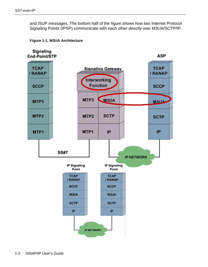
SIGTRAN M3UA - SS7 MTP3-User Adaptation LayerM3UA stands for Message Transfer Part, Level 3, User Adaptation Layer. It is a protocol for transporting SS7 MTP3 User Part messages and MTP3 network management events on top of Streams Control Transmission Protocol (SCTP) to IP-based application processors. An Application Server Process (ASP) is the IP-based instantiation of an application process or database. A Signaling Gateway (SG) terminates an SS7 connection over MTP1-3 and transports SCCP, ISUP, and other MTP3 User messages over the M3UA/SCTP/IP protocols. An Internet Protocol Signalling Point (IPSP) communicates directly with other IPSPs over M3UA.
In Figure 1-1 the legacy SS7 Signaling Endpoint on the far left uses MTP1-3 for sending SCCP and ISUP messages to the network. The Signaling Gateway (SG) does the translation of MTP3 messages into M3UA messages, and uses SCTP/IP to deliver them to the Application Server Process (ASP). At the ASP, M3UA handles the SCCP
Overview 1-1
SS7-over-IP
and ISUP messages. The bottom half of the figure shows how two Internet Protocol Signaling Points (IPSP) communicate with each other directly over M3UA/SCTP/IP.
Figure 1-1. M3UA Architecture
1-2 SINAP/IP User’s Guide

Product
ProductThe SINAP/IP IPAS provides a means for SINAP/SS7 applications to communicate over IP to a Signalling Gateway (SG) without any changes to the applications and with no SS7 links.
The Internet Engineering Task Force (IETF), Signaling Transport (SIGTRAN) working group has a number of Request For Comments (RFC) documents that specify protocols and adaptation layers that can be used to carry SS7 traffic over IP. SINAP/IP uses the MTP3 User Adaptation (M3UA; RFC3332) Layer and the Stream Control Transmission Protocol (SCTP2960; RFC3309) to carry the MTP3 user traffic. The exact versions of these documents can be found on the IETF Web site www.ietf.org.
M3UA here replaces the MTP3 layer, while SCTP provides a Carrier Grade Protocol to replace MTP2. IP here replaces MTP1.
This version of the Internet Protocol Application Server supports TCAP/SCCP traffic for the ITU and ANSI network variants only.
The SINAP/IP IPAS is implemented inside a single program named m3uagw (M3UA Gateway, the package name is M3UAGW). A SINAP/IP IPAS takes SS7 messages from an application and uses M3UA to convert them to IP and vice versa. The installation and operation of m3uagw is described in this document.
This release of the SINAP/IP IPAS is supported on Stratus ft Linux 2.2 and on SINAP/SS7 14.2. It is not possible to run the SINAP/IP IPAS without SINAP/SS7.
M3UA (RFC3332) describes three major SS7-over-IP network entities:
• Application Server Process (ASP). This is an entity which can send and receive SS7 traffic over IP. The ASP represents a number of Application Servers (AS). Each AS is assigned a routing key that identifies the application. Some example routing keys are: the DPC alone, the DPC/OPC combination, or the DPC/OPC/SIO combination.
SINAP/IP IPAS supports TCAP/SCCP traffic over M3UA. The routing keys used are DPC or OPC/DPC.
• DPC. The application is identified using the Destination Point Code. This is referred to as the Partial Key throughout this document. A Signaling Gateway (SG) does not look into data in the TCAP layer. This is fine when TCAP traffic originates from the SS7 side, because each PC is associated with one SS7 node. A problem occurs when multiple ASPs in the IP network load share one DPC: when one of the ASPs sends TC-BEGIN, the returning TC-END or TC-CONTINUE may not be routed back to the originating ASP.
• OPC/DPC. With OPC/DPC Routing Key, the SG further limits traffic distribution to the registered ASP based on the DPC and from a specific OPC. You can
Overview 1-3

Product
configure several ASPs that load share one DPC, with each ASP receiving traffic from a distinct OPC. In this case, since only one ASP is configured for each OPC/DPC routing key, the corresponding TC-END or TC-CONTINUE is guaranteed to be routed back to the originating ASP. With one ASP configured for each OPC/DPC routing key, the override traffic mode will be supported to allow ASP fail over. OPC/DPC routing keys are applicable to SINAP/IP IPAS ASP mode only.
• You must always configure the appropriate routing key for its associated SG. You can configure DPC key, OPC/DPC keys, or combination of both.
• Signaling Gateway (SG). An SG converses with the ASPs, converts M3UA messages to and from SS7 MSUs, and sends and receives MSUs over SS7 links. The SG can also route traffic from an ASP to another ASP; in this case no conversion is done. The SG may be implemented as a number of Signaling Gateway Processes (SGPs).
• Internet Protocol Signaling Point (IPSP). These endpoints communicate directly with one another over M3UA (IP): there are no intermediate SGs or SS7 links. The OPC/DPC routing key is not applicable to IPSP mode. Since IPSP use M3UA in a point-to-point fashion, there is no concept of routing of messages beyond the remote end. Therefore, traffic between the two peer IPSPs is directly based on their point code.
SINAP/IP IPAS implements an ASP or an IPSP conforming to RFCs 3332, 2960, 3309 and the M3UA Implementors Guide, subject to the limitations described below. This version of the Internet Protocol Application Server supports TCAP/SCCP traffic for the ITU and ANSI network variants only.
N O T E
The M3UA Implementor’s Guide is available at http://ietf.org/internet-drafts/.
In order to understand all the applicable commands in Chapter 6, ‘‘Command Reference,” and the operating procedures for the SINAP/IP IPAS, you must be familiar with the terms described in RFC3332 and be knowledgeable about basic entity relationships (for example, multiple SGPs in an SG) and the meaning of multi-homing (see RFC2960).
You also need to have a fundamental understanding of SINAP/SS7 operation, because the SINAP/IP IPAS is layered on top of SINAP; the SINAP/SS7application can only be used with SINAP/SS7 running.
1-4 SINAP/IP User’s Guide

Compliance
In Figure 1-2 the circled area shows the possible uses for the SINAP/IP product.
Figure 1-2. SINAP/IP in the Network
ComplianceThe SINAP/IP IPAS implements an ASP or an IPSP conforming to RFCs 3332, 2960, 3309 and the M3UA Implementor’s Guide
InteroperabilitySINAP/IP IPAS has been tested to interoperate correctly with a Cisco® ITP server.
TDM SignalingNetwork
MobileSwitching
Center (MSC)
ServiceSwitchingPoint (SSP)
IntelligentPeripheral (IP)
TDM CircuitSwitchedNetwork
PacketNetwork
SignalingBearer
Service Management System (SMS)
“Internet Offload”Signaling End Points
(e.g. SCP, HLR)
Media GatewayController (MGC)
“Softswitch”
Core SignalingGateway(Core-SG)
Edge SignalingGateway(Edge-SG)
Application/Feature
Server (AS/FS)
MediaGateway
(MG)
MediaServer (MS)
SIPUser Agent(Client/Server)
Mobile DataNetwork Elements (e.g., GGSN, SGSN)
SIP Server(Proxy, Re-direct,
Registrar)
PresenceServer
Overview 1-5
SINAP/IP Configuration Support
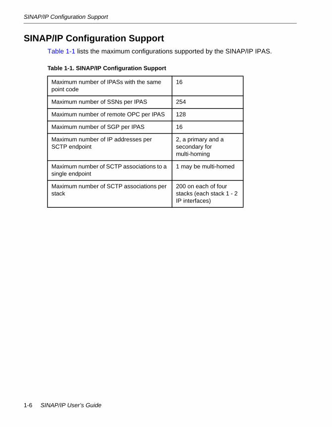
SINAP/IP Configuration SupportTable 1-1 lists the maximum configurations supported by the SINAP/IP IPAS.
Table 1-1. SINAP/IP Configuration Support
Maximum number of IPASs with the same point code
16
Maximum number of SSNs per IPAS 254
Maximum number of remote OPC per IPAS 128
Maximum number of SGP per IPAS 16
Maximum number of IP addresses per SCTP endpoint
2, a primary and a secondary for multi-homing
Maximum number of SCTP associations to a single endpoint
1 may be multi-homed
Maximum number of SCTP associations per stack
200 on each of four stacks (each stack 1 - 2 IP interfaces)
1-6 SINAP/IP User’s Guide
Chapter 2Installation2-
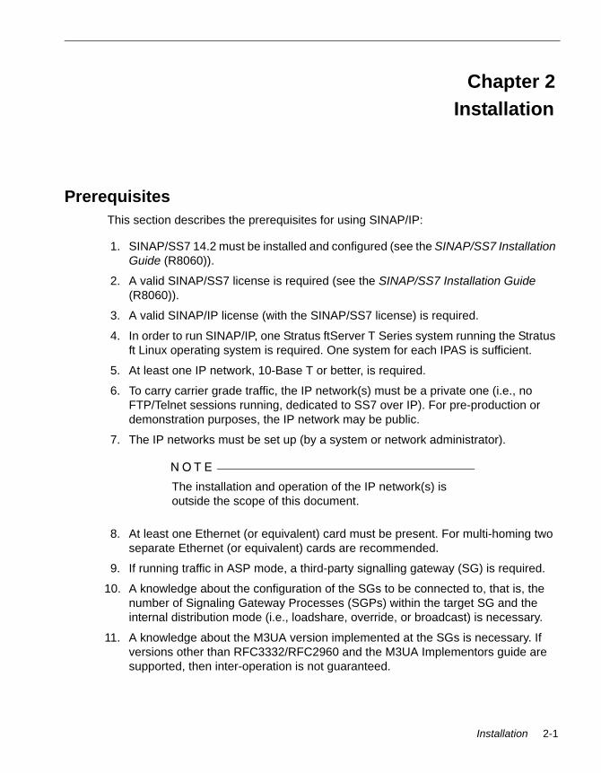
PrerequisitesThis section describes the prerequisites for using SINAP/IP:
1. SINAP/SS7 14.2 must be installed and configured (see the SINAP/SS7 Installation Guide (R8060)).
2. A valid SINAP/SS7 license is required (see the SINAP/SS7 Installation Guide (R8060)).
3. A valid SINAP/IP license (with the SINAP/SS7 license) is required.
4. In order to run SINAP/IP, one Stratus ftServer T Series system running the Stratus ft Linux operating system is required. One system for each IPAS is sufficient.
5. At least one IP network, 10-Base T or better, is required.
6. To carry carrier grade traffic, the IP network(s) must be a private one (i.e., no FTP/Telnet sessions running, dedicated to SS7 over IP). For pre-production or demonstration purposes, the IP network may be public.
7. The IP networks must be set up (by a system or network administrator).
N O T E
The installation and operation of the IP network(s) is outside the scope of this document.
8. At least one Ethernet (or equivalent) card must be present. For multi-homing two separate Ethernet (or equivalent) cards are recommended.
9. If running traffic in ASP mode, a third-party signalling gateway (SG) is required.
10. A knowledge about the configuration of the SGs to be connected to, that is, the number of Signaling Gateway Processes (SGPs) within the target SG and the internal distribution mode (i.e., loadshare, override, or broadcast) is necessary.
11. A knowledge about the M3UA version implemented at the SGs is necessary. If versions other than RFC3332/RFC2960 and the M3UA Implementors guide are supported, then inter-operation is not guaranteed.
Installation 2-1
Installation
InstallationThis chapter describes the installation of m3uagw on Stratus ft Linux systems.
Note that the procedure for installation is similar to that of SINAP/SS7 (see the SINAP/SS7 Installation Guide (R8060)), although no reboot is required (since the package/depot does not contain a kernel file set) and SS7 links are not mandatory. However, the package/depot names contain the name “M3UAGW” as opposed to the name “SINAP”.
For instructions on setting up CD-ROM drives and other system components, see the Stratus ftServer T 30 Systems: Installation Guide (R002L).
Log in as root (superuser) to perform the SINAP/IP installation tasks.
Stratus ft Linux InstallationThe following describes the steps needed for installing SINAP/IP IPAS on an ft Linux system.
• ‘‘Prerequisites for Installing SINAP/IP on ft Linux Systems”
• ‘‘Installing M3UAGW RPM on ft Linux Systems”
• ‘‘Installed Components on ft Linux Systems”
• ‘‘Configuring M3UAGW on ft Linux Systems”
Prerequisites for Installing SINAP/IP on ft Linux Systems• Stratus ft Linux 2.2 installed
• SINAP/SS7 14.2 installed
• A valid license for SINAP/SS7
• A valid license for SINAP/IP
• M3UAGW 1.0 software rpm
• IP network ports
• 5 MB of disk space
• 20 MB of physical memory
Installing M3UAGW RPM on ft Linux Systems1. Login as root.
2. Check and remove existing installation if present.
3. Copy m3uagw rpm to local directory.
2-2 SINAP/IP User’s Guide

Stratus ft Linux Installation
4. Invoke rpm -vi rpm Name to install.
5. Verify installation by invoking rpm -qi m3uagw.
Installed Components on ft Linux Systems• Configuration script - /etc/config_m3uagw
• M3UAGW master directory - /home/m3uagw_master in ft Linux
• Executables in /home/m3uagw_master/Bin directory
• m3uagw. The m3ua gateway (IPAS)
• m3uagw_trace. The gateway tracing tools
• m3uagw_license_update. The license update program
• m3uagw_send_cm. The user management client; sends commands to the gateway
root@ftlinux0]# rpm -qi m3uagwpackage m3uagw is not installed[root@ftlinux0]# rpm -vi m3uagw-1.0.0.0_15BE-1.i386.rpmPreparing packages for installation...
Starting Preinstall Script ...Preinstall script completem3uagw-1.0.0.0_15BE051104-1Postinstall script complete[root@ftlinux0]# rpm -qi m3uagw
Name : m3uagw Relocations: (not relocateable)Version : 1.0.0.0_15BE051104 Vendor: Stratus Technologies, Inc.Release : 1 Build Date: Tue 11 May 2004 02:50:14 PM EDTInstall Date: Wed 12 May 2004 05:56:08 PM EDT Build Host: ftlinux2.hw.stratus.comGroup : Applications/Communications Source RPM: m3uagw-1.0.0.0_15BE051104-1.src.rpmSize : 3382553 License: 2003 Stratus Technologies Bermuda, Ltd.All rights reserved.Signature : (none)Summary : Stratus Technologies M3UA Gateway ProductDescription :Stratus Technologies M3UA Gateway ProductThis m3uagw version was built with the following layered product versions: SINAP/SS7 version: 14.2.0.0_16BE TME-SIGTRAN version: 1.0.0.0_08BE
Installation 2-3
M3UAGW Master Directory Structure
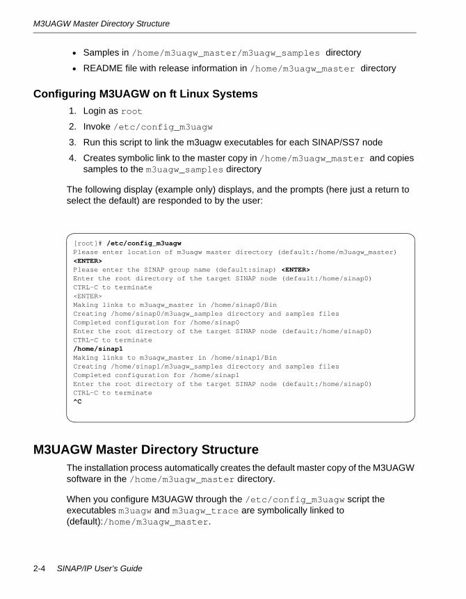
• Samples in /home/m3uagw_master/m3uagw_samples directory
• README file with release information in /home/m3uagw_master directory
Configuring M3UAGW on ft Linux Systems1. Login as root
2. Invoke /etc/config_m3uagw
3. Run this script to link the m3uagw executables for each SINAP/SS7 node
4. Creates symbolic link to the master copy in /home/m3uagw_master and copies samples to the m3uagw_samples directory
The following display (example only) displays, and the prompts (here just a return to select the default) are responded to by the user:
M3UAGW Master Directory StructureThe installation process automatically creates the default master copy of the M3UAGW software in the /home/m3uagw_master directory.
When you configure M3UAGW through the /etc/config_m3uagw script the executables m3uagw and m3uagw_trace are symbolically linked to (default):/home/m3uagw_master.
[root]# /etc/config_m3uagw Please enter location of m3uagw master directory (default:/home/m3uagw_master) <ENTER>Please enter the SINAP group name (default:sinap) <ENTER>Enter the root directory of the target SINAP node (default:/home/sinap0)CTRL-C to terminate<ENTER>Making links to m3uagw_master in /home/sinap0/BinCreating /home/sinap0/m3uagw_samples directory and samples filesCompleted configuration for /home/sinap0Enter the root directory of the target SINAP node (default:/home/sinap0)CTRL-C to terminate/home/sinap1Making links to m3uagw_master in /home/sinap1/BinCreating /home/sinap1/m3uagw_samples directory and samples filesCompleted configuration for /home/sinap1Enter the root directory of the target SINAP node (default:/home/sinap0)CTRL-C to terminate^C
2-4 SINAP/IP User’s Guide

Automatically Restart m3uagw
N O T E
The accounts the executables are executed from must be in the SINAP/SS7 group.
Although /home/sinap_master is assumed by default for the Stratus ft Linux operating system you can specify a different location, for example /usr/home during the installation.
The contents of the directory will be (default):
• /[opt | home]
• /m3uagw_master
• README
• /Bin
• m3uagw
• m3uagw_trace
• m3uagw_license_update
• /m3uagw_samples
• m3uagw_send_cm
Automatically Restart m3uagwThe sinap_utlmon utility can be used to monitor and automatically restart m3uagw. Refer to the SINAP/SS7 User’s Guide (R8051) for details on sinap_utlmon and how to configure SINAP/SS7 to be restarted upon system reboot.
To enable m3uagw to be monitored and restarted by sinap_utlmon:
1. Login as SINAP/SS7 user, e.g. su - sinap0
2. Remove symbolic link for ~/Bin/startappl, e.g. rm ~/Bin/startappl.
3. Copy the startappl from its master copy (should use identical permission), e.g.
cp /home/sinap_master/Bin/startappl ~/Bin/startapplchmod 777 ~/Bin/startappl
4. Edit ~/Bin/startappl to add sinap_utlmon, m3uagw, and the m3uagw startup configuration file. Use a line similar to the following before the final “exit”:
/home/sinap0/Bin/sinap_utlmon /home/sinap0/Bin/m3uagw/home/sinap0/asp.cfg
Installation 2-5

Automatically Restart m3uagw
N O T E
Full paths to sinap_utlmon, m3uagw and its startup configuration file argument are required.
Use the OUTPUT_FILE command to direct m3uagw's console output to a file because the console is not applicable when m3uagw is being restarted. The following is a sample command:
OUTPUT_FILE = /home/sinap0/asp.out
5. Test that m3uagw will be started adn restarted by sinap_utlmon. Start or restart SINAP/SS7. Monitor that m3uagw is started correctly by SINAP/SS7 using the SINAP/SS7 command ver and examining the m3uagw log file.
6. Shut down m3uagw, for example, eneter the following command:
m3uagw_send_cm -s "SHUTDOWN"
Monitor that m3uagw is started correctly by SINAP/SS7 using the SINAP/SS7 ver command and examining the m3uagw log file.
2-6 SINAP/IP User’s Guide

Chapter 3Quick-Start Guide3-
The quick verification consists of MML (Man-Machine Language) and m3uagw startup configuration files for two IPSP nodes in dynamic registration mode, so you can use two SINAP/SS7 nodes to verify the basic integrity and functionality of the M3UAGW package.
The sample files were installed in the $M3UAGW_MASTER/Samples directory and were copied by /etc/config_m3uagw to each node's m3uagw_samples directory. A README file in that directory describes how to set up and run the samples.
To perform the M3UAGW sample setup and running procedures, see the relevant following sections:
• ‘‘Create and Configure SINAP/SS7 Nodes - ITU
• ‘‘Create and Configure SINAP/SS7 Nodes - ANSI
• ‘‘Start m3uagw process - ITU/ANSI
• ‘‘Run Traffic Using tcsend/tcrecv - ITU
• ‘‘Run Traffic Using tcsend/tcrecv - ANSI
Create and Configure SINAP/SS7 Nodes - ITU1. Create two fresh SINAP/SS7 ITU(CCITT) nodes using /etc/config_sinap.
One will be used as the IPSP server, the other as the IPSP client.
N O T E
If a Multi-Stack license is purchased and the system has two Ethernet interfaces available and configured, these two nodes can reside on the same system. Otherwise, two systems are required to run the sample.
2. Make sure that the /etc/SS7links file is empty.
3. Start SINAP/SS7 on both nodes with start_sinap.
4. Run /etc/config_m3uagw for each created node.
5. Log in to the server node and change directory to m3uagw_samples.
Quick-Start Guide 3-1
Create and Configure SINAP/SS7 Nodes - ANSI
6. Feed the MML to the node by invoking send_cm server-itu.mml.
7. Log in to the client node and change directory to m3uagw_samples.
8. Feed the MML to the node by invoking send_cm client-itu.mml.
9. Verify that no error is reported.
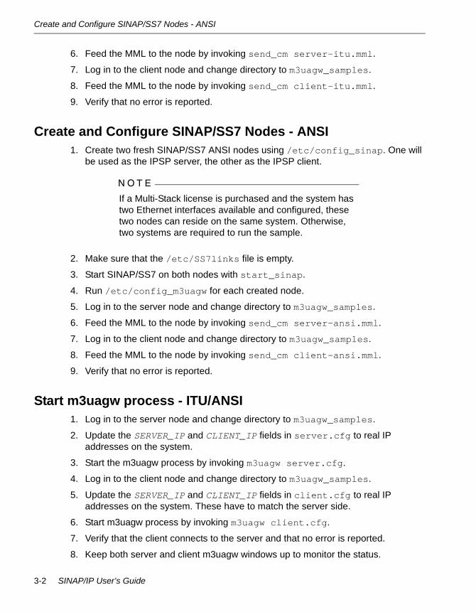
Create and Configure SINAP/SS7 Nodes - ANSI1. Create two fresh SINAP/SS7 ANSI nodes using /etc/config_sinap. One will
be used as the IPSP server, the other as the IPSP client.
N O T E
If a Multi-Stack license is purchased and the system has two Ethernet interfaces available and configured, these two nodes can reside on the same system. Otherwise, two systems are required to run the sample.
2. Make sure that the /etc/SS7links file is empty.
3. Start SINAP/SS7 on both nodes with start_sinap.
4. Run /etc/config_m3uagw for each created node.
5. Log in to the server node and change directory to m3uagw_samples.
6. Feed the MML to the node by invoking send_cm server-ansi.mml.
7. Log in to the client node and change directory to m3uagw_samples.
8. Feed the MML to the node by invoking send_cm client-ansi.mml.
9. Verify that no error is reported.
Start m3uagw process - ITU/ANSI1. Log in to the server node and change directory to m3uagw_samples.
2. Update the SERVER_IP and CLIENT_IP fields in server.cfg to real IP addresses on the system.
3. Start the m3uagw process by invoking m3uagw server.cfg.
4. Log in to the client node and change directory to m3uagw_samples.
5. Update the SERVER_IP and CLIENT_IP fields in client.cfg to real IP addresses on the system. These have to match the server side.
6. Start m3uagw process by invoking m3uagw client.cfg.
7. Verify that the client connects to the server and that no error is reported.
8. Keep both server and client m3uagw windows up to monitor the status.
3-2 SINAP/IP User’s Guide

Run Traffic Using tcsend/tcrecv - ITU
9. For expected outputs, refer to the sample M3UAGW log file in Chapter 4, ‘‘ASP Mode.”
Run Traffic Using tcsend/tcrecv - ITU1. Log in to the client node and change directory to the samples/ccitt directory.
2. Start tcrecv by invoking tcrecv -l 2 -r 2 -c.
3. In another window, log in to the server node and change directory to the samples/ccitt directory.
4. Start tcsend by invoking tcsend -p 1000 -l 2 -r 2 -w 10 -q 0.
5. The traffic should start running and no LOCAL_CANCEL messages should appear.
Run Traffic Using tcsend/tcrecv - ANSI1. Log in to the client node and change directory to the samples/ansi directory.
2. Start tcrecv by invoking tcrecv 0 2 2 1.
3. In another window, log in to the server node and change directory to the samples/ansi directory.
4. Start tcsend by invoking tcsend 0 0 2 2 254 54 1.
5. The traffic should start running and no LOCAL_CANCEL messages should appear.
Quick-Start Guide 3-3

Run Traffic Using tcsend/tcrecv - ANSI
3-4 SINAP/IP User’s Guide

Chapter 4ASP Mode4-
Figure 4-1 shows the basic configuration for SINAP/IP IPAS connected through a gateway to SINAP/SS7. IPAS ASP should be able to talk to any standard conforming SG. The gateway is used as an example to illustrate the ASP operation.
Figure 4-1. SINAP/IP ASP Basic Configuration
IPAS Startup FilesThe IPAS receives its startup configuration from a flat file whose name is specified in the first and only command line argument. The syntax is as follows:
m3uagw [file_name ]
In this syntax, m3uagw is the name of the M3UA Gateway program that implements the IPAS.
If file_name is omitted, the file name is preset to m3uagw_startup; and if this file does not exist, a fatal error is returned.
ftServer
SS7ToIP
GatewaySINAPSINAPIPASIPAS
SINAPSINAPSS7SS7
ftServer
IP SS7
SGPASP SS7 SEP
ASP Mode 4-1

ITU Software Configuration
ITU Software ConfigurationFigure 4-2 shows a sample minimal configuration for an ITU (CCITT) ASP.
Figure 4-2. Sample ITU ASP Configuration
Minimal IPAS Startup File Example for ITUThe following startup file is a typical startup file that is used solely for demonstration purposes. A complete description of each command is provided in Chapter 6, ‘‘Command Reference”.
Figure 4-3. IPAS ITU Startup Config File
• GATEWAY_MODE = IPAS indicates the operation mode of the gateway (IPAS/IPMT). IPAS is the mode currently supported. IPSP also uses IPAS mode. Future releases may include an IPMT (IPAS and IPMT are SINAP/IP terms, not RFC3332).
• PRIMARY_LOCAL_HOST refers to the local IP address used to connect to the SGP.
• LOCAL_SCTP_PORT refers to the local SCTP port that will be used to send to and receive on the SGP.
GATEWAY_MODE = IPASPRIMARY_LOCAL_HOST = 192.168.1.100LOCAL_SCTP_PORT = 2905M3UA_SG_TO_SGP_DISTRIBUTION_MODE = 1 LOADSHAREADD_IP_ROUTE = 1 192.168.1.50 2905 route1ADD_IP_CPC = 1 2669ADD_DPC_KEY = LOADSHARE 1000 1DEBUG_LEVEL = 1
P C =2 66 5
S IN A P D river
IP A S
P C =2 669
S IN A P D riverIP
Tra
ffic
tc recvS S N = 2
tcsen dS S N = 2
S S 7T oIP
G atew a y
P C =2 66 7
SS7
Traf
fic
4-2 SINAP/IP User’s Guide

ITU Software Configuration
• M3UA_SG_TO_SGP_DISTRIBUTION_MODE declares an SG, assigns an SG ID, and specifies the traffic distribution mode in this SG.
• ADD_IP_ROUTE = 1 192.168.1.50 2905 route1 identifies the destination that we will be talking to. The first parameter is the SG. Id., mandatory to enter (this line declares an SGP connection, and the SGP is part of the SG we declared above with SG ID “1”). The second parameter is the destination system (in hostname or canonical IP address format). The third parameter is the SCTP port of the destination, and the last parameter is a symbolic name for the IP route.
N O T E
The symbolic name could be used to tag the point code of an adjacent SG, but if so, it must be alphanumeric (for example PC2000).
Each ADD_IP_ROUTE line is equivalent to a set of one or more physical paths between m3uagw (ASP) and an SGP.
• ADD_IP_CPC = 1 2669. Specifies the SG ID and one or more concerned point codes (CPCs) reachable through this SG. It is mandatory to have at least one CPC entered that is reachable over IP. The CPCs are the point codes of the ultimate destinations that traffic will reach. Also SINAP/SS7 must be set up correctly so that its MML includes the CPCs identified here.
• ADD_DPC_KEY = LOADSHARE 1000 1. Specifies the routing context value of the local routing key. This configuration uses DPC key. LOADSHARE is the traffic mode. The second parameter is the routing context value of the routing key. The third parameter is the SG ID. The configuration on the remote SG should match this DPC key configuration.
• DEBUG_LEVEL = 1. Refers to the level of diagnostic tracing and error reporting that will appear. Debug level 1 is the level preferred by development.
Note that it is customary to set DEBUG_LEVEL = 1 here to give some extra view of activity in Demonstration mode.
ITU MMLAs in SINAP/SS7, MML must be set up correctly at the SINAP/SS7 node where the IPAS is to be run.
See the SINAP/SS7 User’s Guide (R8051) for information on MML commands.
This example is for ITU, International Network (INAT00). It is necessary to configure and activate fake routesets, linksets, and a link (create only). There can be installed active SS7 links at the node where the IPAS runs, but the fake link for IPAS must be on a port that does not exist in the SS7links file for that node.
ASP Mode 4-3
ITU Software Configuration
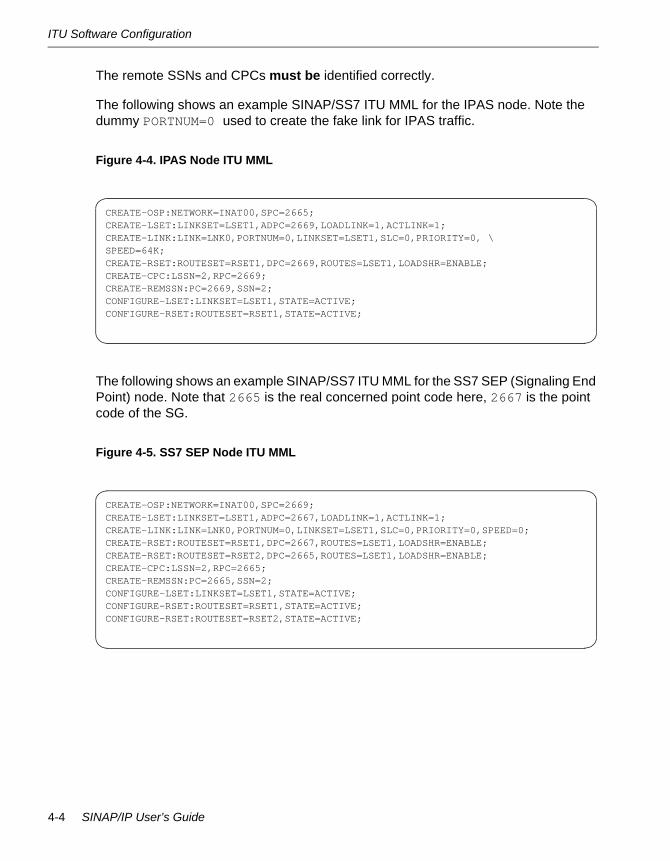
The remote SSNs and CPCs must be identified correctly.
The following shows an example SINAP/SS7 ITU MML for the IPAS node. Note the dummy PORTNUM=0 used to create the fake link for IPAS traffic.
Figure 4-4. IPAS Node ITU MML
The following shows an example SINAP/SS7 ITU MML for the SS7 SEP (Signaling End Point) node. Note that 2665 is the real concerned point code here, 2667 is the point code of the SG.
Figure 4-5. SS7 SEP Node ITU MML
CREATE-OSP:NETWORK=INAT00,SPC=2665;CREATE-LSET:LINKSET=LSET1,ADPC=2669,LOADLINK=1,ACTLINK=1;CREATE-LINK:LINK=LNK0,PORTNUM=0,LINKSET=LSET1,SLC=0,PRIORITY=0, \SPEED=64K;CREATE-RSET:ROUTESET=RSET1,DPC=2669,ROUTES=LSET1,LOADSHR=ENABLE;CREATE-CPC:LSSN=2,RPC=2669;CREATE-REMSSN:PC=2669,SSN=2;CONFIGURE-LSET:LINKSET=LSET1,STATE=ACTIVE;CONFIGURE-RSET:ROUTESET=RSET1,STATE=ACTIVE;
CREATE-OSP:NETWORK=INAT00,SPC=2669;CREATE-LSET:LINKSET=LSET1,ADPC=2667,LOADLINK=1,ACTLINK=1;CREATE-LINK:LINK=LNK0,PORTNUM=0,LINKSET=LSET1,SLC=0,PRIORITY=0,SPEED=0;CREATE-RSET:ROUTESET=RSET1,DPC=2667,ROUTES=LSET1,LOADSHR=ENABLE;CREATE-RSET:ROUTESET=RSET2,DPC=2665,ROUTES=LSET1,LOADSHR=ENABLE;CREATE-CPC:LSSN=2,RPC=2665;CREATE-REMSSN:PC=2665,SSN=2;CONFIGURE-LSET:LINKSET=LSET1,STATE=ACTIVE;CONFIGURE-RSET:ROUTESET=RSET1,STATE=ACTIVE;CONFIGURE-RSET:ROUTESET=RSET2,STATE=ACTIVE;
4-4 SINAP/IP User’s Guide

ANSI Software Configuration
ANSI Software ConfigurationFigure 4-6 Show a sample configuration for an ANSI ASP.
Figure 4-6. Sample ANSI ASP Configuration
Sample IPAS Startup File for ANSIThe following is a typical startup file that is solely for demonstration purposes. A complete description of each command is provided in Chapter 6, ‘‘Command Reference.”
Figure 4-7. IPAS ANSI Startup Config File
The following describes the entry that differs from the ITU example above.
• ADD_IP_CPC = 1 4-4-4. Identifies the SG ID and one or more concerned point codes (CPCs) reachable via this SG. This is the only difference from the ITU example above. It is mandatory to have at least one CPC entered that is reachable over IP. A CPCs is the point code of the ultimate destination that traffic will reach. Also SINAP/SS7 must be set up correctly so that its MML includes the CPCs identified here.
GATEWAY_MODE = IPASPRIMARY_LOCAL_HOST = 192.168.1.100LOCAL_SCTP_PORT = 2905M3UA_SG_TO_SGP_DISTRIBUTION_MODE = 1 LOADSHAREADD_IP_ROUTE = 1 192.168.1.50 2905 route1ADD_IP_CPC = 1 4-4-4ADD_DPC_KEY = LOADSHARE 1000 1DEBUG_LEVEL = 1
PC=2-2-2
SINAP Driver
IPAS
PC=4-4-4
SINAP DriverIP
Tra
ffic
tcrecvSSN=2
tcsendSSN=2SS7
ToIP
GatewayPC=3-3-3
SS7
Traf
fic
ASP Mode 4-5

ANSI Software Configuration
ANSI MMLAs in SINAP/SS7, MML must be set up correctly at the SINAP/SS7 node where the IPAS is to be run.
See the SINAP/SS7 User’s Guide (R8051) for information on MML Commands.
The following example MML file is for ANSI and the National Network (NAT10). It is necessary to configure and activate fake routesets, linksets, and a link (create only). There can be installed active SS7 links at the node where the IPAS runs, but the fake link for IPAS must be on a port that does not exist in the SS7links file for that node.
The remote SSNs and CPCs must be identified correctly.
Figure 4-8 shows the example SINAP/SS7 ANSI MML for the IPAS node. Note the dummy PORTNUM=0 used to create the fake link for IPAS traffic.
Figure 4-8. IPAS Node ANSI MML
CREATE-OSP:NETWORK=NAT10,SPC=2-2-2;CREATE-LSET:LINKSET=LSET1,ADPC=4-4-4,TYPE=F,LOADLINK=1,ACTLINK=1;CREATE-LINK:LINK=LNK1,PORTNUM=0,LINKSET=LSET1,SLC=0,PRIORITY=0,SPEED=0;CREATE-RSET:ROUTESET=RSET1,DPC=4-4-4,ROUTES=LSET1;CREATE-CPC:LSSN=2,RPC=4-4-4;CREATE-REMSSN:PC=4-4-4,SSN=2;CONFIGURE-LSET:LINKSET=LSET1,STATE=ACTIVE;CONFIGURE-RSET:ROUTESET=RSET1,STATE=ACTIVE;
4-6 SINAP/IP User’s Guide

ANSI Software Configuration
Figure 4-9 shows the example SINAP/SS7 ANSI MML for the SS7 SEP node.
Figure 4-9. SS7 SEP Node ANSI MML
N O T E
Since many ANSI network devices default to 56K link speed, sometimes it is necessary to explicitly specify SPEED=56K for ANSI SS7 links if 56K is the speed used by the SG.
The link LNK9, linkset LSET9 and its ADPC 9-9-9 and the port number 9 used by LNK9 are all dummies. These are needed because a combined linkset in ANSI requires at least 2 linksets in it. In CSET1, only LSET1 will be activated and used to route traffic.
CREATE-OSP:NETWORK=NAT10,SPC=4-4-4;CREATE-LSET:LINKSET=LSET1,ADPC=3-3-3,TYPE=A,LOADLINK=1,ACTLINK=1;CREATE-LSET:LINKSET=LSET9,ADPC=9-9-9,TYPE=A,LOADLINK=1,ACTLINK=1;CREATE-LINK:LINK=LNK0,PORTNUM=0,LINKSET=LSET1,SLC=0,PRIORITY=0,SPEED=0;CREATE-LINK:LINK=LNK9,PORTNUM=9,LINKSET=LSET9,SLC=0,PRIORITY=0,SPEED=0;CREATE-CLSET:CLSET=CSET1,LSET1=LSET1,LSET2=LSET9;CREATE-RSET:ROUTESET=RSET1,DPC=3-3-3,ROUTES=CSET1;CREATE-RSET:ROUTESET=RSET2,DPC=2-2-2,ROUTES=CSET1;CREATE-CPC:LSSN=2,RPC=2-2-2;CREATE-REMSSN:PC=2-2-2,SSN=2;CONFIGURE-LSET:LINKSET=LSET1,STATE=ACTIVE;CONFIGURE-RSET:ROUTESET=RSET1,STATE=ACTIVE;CONFIGURE-RSET:ROUTESET=RSET2,STATE=ACTIVE;
ASP Mode 4-7
Starting the IPAS
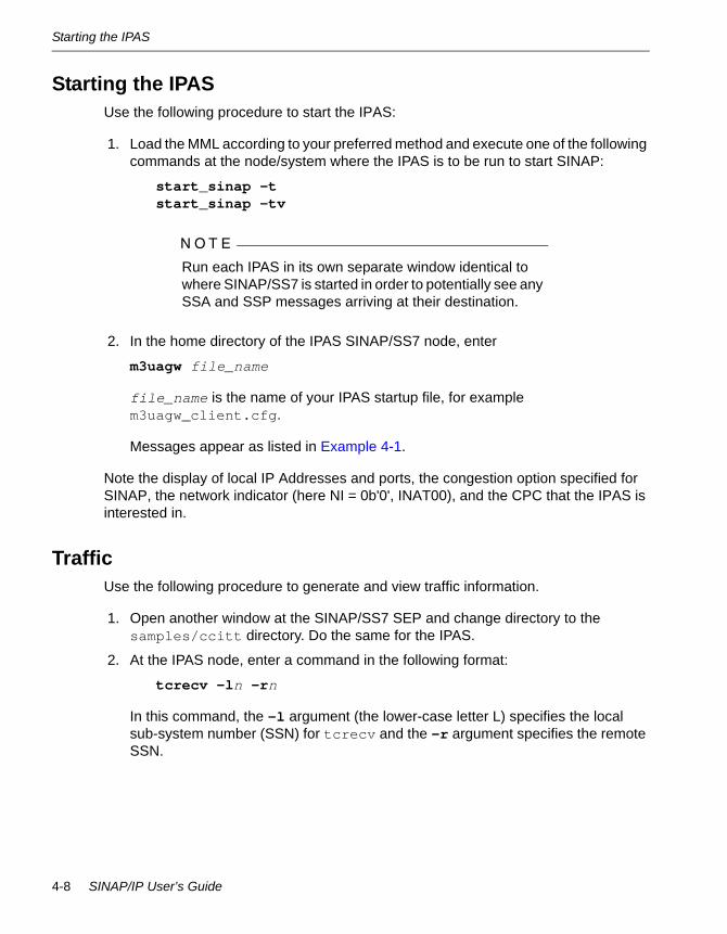
Starting the IPASUse the following procedure to start the IPAS:
1. Load the MML according to your preferred method and execute one of the following commands at the node/system where the IPAS is to be run to start SINAP:
start_sinap -t start_sinap -tv
N O T E
Run each IPAS in its own separate window identical to where SINAP/SS7 is started in order to potentially see any SSA and SSP messages arriving at their destination.
2. In the home directory of the IPAS SINAP/SS7 node, enter
m3uagw file_name
file_name is the name of your IPAS startup file, for example m3uagw_client.cfg.
Messages appear as listed in Example 4-1.
Note the display of local IP Addresses and ports, the congestion option specified for SINAP, the network indicator (here NI = 0b'0', INAT00), and the CPC that the IPAS is interested in.
TrafficUse the following procedure to generate and view traffic information.
1. Open another window at the SINAP/SS7 SEP and change directory to the samples/ccitt directory. Do the same for the IPAS.
2. At the IPAS node, enter a command in the following format:
tcrecv -ln -rn
In this command, the -l argument (the lower-case letter L) specifies the local sub-system number (SSN) for tcrecv and the -r argument specifies the remote SSN.
4-8 SINAP/IP User’s Guide

Traffic
At the SS7 SEP you might see messages similar to the following:
Note these messages are generated by SCMG (SCCP Management), signify that the remote end is receiving the SSA over SS7 over IP, and indicate that there are no SS7 links present here.
3. At the SS7 SEP samples/ccitt directory, enter a command in the following format:
tcsend -l2 -r2 -p2665 -w20
The -l and -r options refer to the local and remote SSNs respectively. The -p option refers to the point code where the remote SSN is resident. The -w option here instructs tcsend to send 20 MSUs before waiting for replies. When traffic starts to flow, expect to see messages similar to the following:
These messages indicate that you have successfully sent TCAP traffic over IP using the SS7 over IP standards M3UA and SCTP.
N O T E
When re-entering this procedure, that is after stopping either tcsend or tcrecv and restarting them later, note that correct operation will not appear until after SSTs have been responded to by an SSA (same as SINAP). Wait until the SSA about the remote appears at the tcsend window before starting it or until sy #SC,cpc/ssn indicates an allowed remote subsystem. Otherwise, a TC-NOTICE may appear.
SSA RECEIVED FOR SSN 2 AT PC 2665SSN 2 AT PC 2665 SSN FOUNDSSN 2 AT PC 2665 SET ALLOWED
TCAP SEND: TCAP Messages=14200 TBlocks->tx=42600 rx=42600 local cancel=0TCAP SEND: TCAP Messages=14300 TBlocks->tx=42900 rx=42900 local cancel=0TCAP SEND: TCAP Messages=14400 TBlocks->tx=43200 rx=43200 local cancel=0TCAP SEND: TCAP Messages=14500 TBlocks->tx=43500 rx=43500 local cancel=0TCAP SEND: TCAP Messages=14600 TBlocks->tx=43800 rx=43800 local cancel=0TCAP SEND: TCAP Messages=14700 TBlocks->tx=44100 rx=44100 local cancel=0
ASP Mode 4-9

Shutdown
ShutdownAt the IPAS type a Ctrl+C. A graceful shutdown sequence will be executed and the process terminated.
Operation and MaintenanceThe following is a list of IPAS software diagnostics:
• M3UAGW log analysis
• M3UAGW trace
• SINAP/SS7 sy commands
• Ethereal
M3UAGW Log AnalysisThe following are IPAS commands for M3UAGW log analysis:
• Set log output file:
• Use OUTPUT_FILE = file name
• If not specified, defaults to stdout
• Set debug level 1 - 6
• Use DEBUG_LEVEL = level
• Enable M3UA stack trace:
• Use ENABLE_M3UA_TRACE
• Enable SCTP stack trace:
• Use ENABLE_SCTP_TRACE
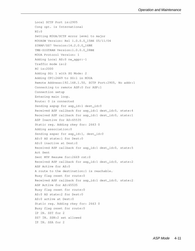
Example 4-1. Sample M3UAGW Log File
GATEWAY_MODE: IPAS
PRIMARY_LOCAL_HOST 192.168.1.103
LOCAL_SCTP_PORT 2905
M3UA_SG_TO_SGP_DISTRIBUTION_MODE 1 LOADSHARE
USING M3UA ASP PROTOCOL
ADD_IP_ROUTE[0]: SG Id.:1 ADDRESS:192.168.1.50 TXPORT:2905 route1
ADD_IP_CPC 1 2669
DEBUG_LEVEL: 1
IPAS license checked out...
Local Address 0 is:192.168.1.103
4-10 SINAP/IP User’s Guide
Operation and Maintenance
Local SCTP Port is:2905
Cong opt. is International
NI:0
Setting M3UA/SCTP error level to major
M3UAGW Version: Rel 1.0.0.0_15BE 05/11/04
SINAP/SS7 Version:14.2.0.0_16BE
TME-SIGTRAN Version:1.0.0.0_08BE
M3UA Protocol Version: 1
Adding Local AS:0 nw_appr:-1
Traffic mode is:2
RC is:2000
Adding SG: 1 with SG Mode: 2
Adding CPC:2669 to SG:1 in M3UA
Remote Address:192.168.1.50, SCTP Port:2905, No addr:1
Connecting to remote ASP:0 for ASP:1
Connection setup
Entering main loop.
Route: 0 is connected
Sending aspup for asp_id:1 dest_id:0
Received ASP callback for asp_id:1 dest_id:0, state:4
Received ASP callback for asp_id:1 dest_id:0, state:1
ASP Inactive for AS:65535
Static reg. Adding rkey for: 2663 0
Adding association:0
Sending aspac for asp_id:1, dest_id:0
AS:0 AS state:1 for Dest:0
AS:0 inactive at Dest:0
Received ASP callback for asp_id:1 dest_id:0, state:5
Act Sent
Sent MTP Resume for:2669 rst:0
Received ASP callback for asp_id:1 dest_id:0, state:2
ASP Active for AS:0
A route to the destination:1 is reachable.
Busy flag reset for route:0
Received ASP callback for asp_id:1 dest_id:0, state:2
ASP Active for AS:65535
Busy flag reset for route:0
AS:0 AS state:2 for Dest:0
AS:0 active at Dest:0
Static reg. Adding rkey for: 2663 0
Busy flag reset for route:0
IP IN. SST for 2
SS7 IN. SSN:2 set allowed
IP IN. SSA for 2
ASP Mode 4-11

Operation and Maintenance
<<< The DATA traffic can flow at this point >>>
<<< Stop the application and shutdown m3uagw >>>
IP IN. SSP for 2
SIGINT Handler invoked.
Entering graceful shutdown
Sent MTP Pause for:2669 rst:0
Key:0 marked:1
Requesting Deferred AS:0 deactivated
Sending aspia for asp_id:1 dest_id:0
Deleting association:0
Delete rkey PC:2663 SSN:0
Sent MTP Pause for:2669 rst:0
Received ASP callback for asp_id:1 dest_id:0, state:6
Inact Sent
Received ASP callback for asp_id:1 dest_id:0, state:1
ASP Inactive for AS:65535
Sending ASP Down to:0
Busy flag reset for route:0
Received ASP callback for asp_id:1 dest_id:0, state:3
Received ASP callback for asp_id:1 dest_id:0, state:0
ASP Down for AS:65535
AS:0 AS state:3 for Dest:0
Route: 0 is disconnected
Deleting SGP:0
Deleting SG:1
Deleting all CPC from SG:1
Deleting CPC: 2669
Route state reset for route:0
Terminating this process.
M3UAGW Trace Tool1. Log in as the SINAP/SS7 user at the SINAP/SS7 node running IPAS.
2. At the command line, type m3uagw_trace.
4-12 SINAP/IP User’s Guide

Operation and Maintenance
The following tracing information is shown:
• Version
• Operating mode
• Route status
• Route history
Figure 4-10. Sample m3uagw_trace Output
Monitoring SCTP/M3UA Traffic Using Ethereal1. Do one of the following:
• Install Ethereal package (part of the ft Linux open packages CD) on your ftServer system.
• Use out-board Linux machine with Ethereal installed (must use Hub).
2. At the command line, type ethereal to start.
3. Select Capture->Start to open the capture option window.
4. Use filter ip[9] == 132 to capture all SCTP traffic.
5. Select the appropriate interface, mode, and filter and click OK to start capturing.
M3UAGW Version: Rel 1.0.0.0_15BE 05/11/04==== M3UAGW-INFOGateway Mode: IPASGateway Protocol: ASP
==== M3UAGW-ROUTES---- route 0 ---- Name: route1 - PROVISIONED IP Address:192.168.1.50 IP Address: TX Port:2905 SG Id:1 ACCESSIBLE, TRAFFIC ALLOWED, SCTP UNCONGESTED
==== M3UAGW-RKEYS (local)---- rkey partial ---- DPC:2665 SSN:0 Mode:LOADSHARE
==== M3UAGW-RKEYS (remote)
==== M3UAGW-ROUTES trace00 TRACE_PROVISION_ROUTE (route 0 route1) 2004-05-17 11:39:47:84501 TRACE_ROUTE_ACCESSIBLE (route 0 route1) 2004-05-17 11:39:51:364
==== M3UAGW-RKEYS trace00 TRACE_ADD_RKEY (partial rkey, pc:2665) 2004-05-17 11:39:51:096
ASP Mode 4-13
Operation and Maintenance
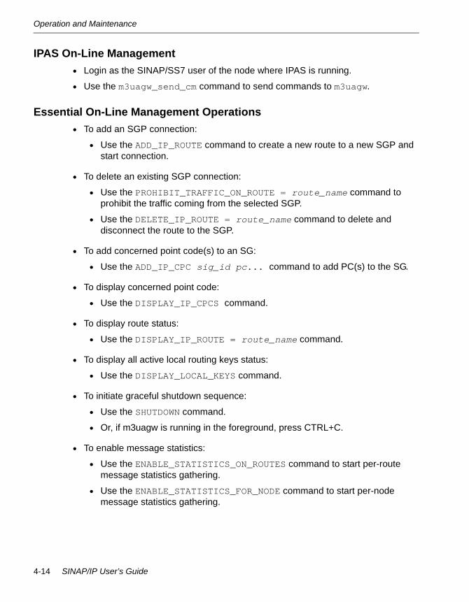
IPAS On-Line Management• Login as the SINAP/SS7 user of the node where IPAS is running.
• Use the m3uagw_send_cm command to send commands to m3uagw.
Essential On-Line Management Operations• To add an SGP connection:
• Use the ADD_IP_ROUTE command to create a new route to a new SGP and start connection.
• To delete an existing SGP connection:
• Use the PROHIBIT_TRAFFIC_ON_ROUTE = route_name command to prohibit the traffic coming from the selected SGP.
• Use the DELETE_IP_ROUTE = route_name command to delete and disconnect the route to the SGP.
• To add concerned point code(s) to an SG:
• Use the ADD_IP_CPC sig_id pc... command to add PC(s) to the SG.
• To display concerned point code:
• Use the DISPLAY_IP_CPCS command.
• To display route status:
• Use the DISPLAY_IP_ROUTE = route_name command.
• To display all active local routing keys status:
• Use the DISPLAY_LOCAL_KEYS command.
• To initiate graceful shutdown sequence:
• Use the SHUTDOWN command.
• Or, if m3uagw is running in the foreground, press CTRL+C.
• To enable message statistics:
• Use the ENABLE_STATISTICS_ON_ROUTES command to start per-route message statistics gathering.
• Use the ENABLE_STATISTICS_FOR_NODE command to start per-node message statistics gathering.
4-14 SINAP/IP User’s Guide
M3UAGW ASP Commands
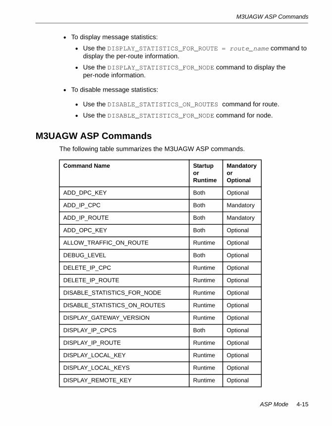
• To display message statistics:
• Use the DISPLAY_STATISTICS_FOR_ROUTE = route_name command to display the per-route information.
• Use the DISPLAY_STATISTICS_FOR_NODE command to display the per-node information.
• To disable message statistics:
• Use the DISABLE_STATISTICS_ON_ROUTES command for route.
• Use the DISABLE_STATISTICS_FOR_NODE command for node.
M3UAGW ASP CommandsThe following table summarizes the M3UAGW ASP commands.
Command Name Startup or Runtime
Mandatory or Optional
ADD_DPC_KEY Both Optional
ADD_IP_CPC Both Mandatory
ADD_IP_ROUTE Both Mandatory
ADD_OPC_KEY Both Optional
ALLOW_TRAFFIC_ON_ROUTE Runtime Optional
DEBUG_LEVEL Both Optional
DELETE_IP_CPC Runtime Optional
DELETE_IP_ROUTE Runtime Optional
DISABLE_STATISTICS_FOR_NODE Runtime Optional
DISABLE_STATISTICS_ON_ROUTES Runtime Optional
DISPLAY_GATEWAY_VERSION Runtime Optional
DISPLAY_IP_CPCS Both Optional
DISPLAY_IP_ROUTE Runtime Optional
DISPLAY_LOCAL_KEY Runtime Optional
DISPLAY_LOCAL_KEYS Runtime Optional
DISPLAY_REMOTE_KEY Runtime Optional
ASP Mode 4-15

M3UAGW ASP Commands
DISPLAY_REMOTE_KEYS Runtime Optional
DISPLAY_STATISTICS_FOR_NODE Runtime Optional
DISPLAY_STATISTICS_FOR_ROUTE Runtime Optional
DISPLAY_SCTP_PARAMETERS Both Optional
DYNAMIC_REGISTRATION Startup Optional
ENABLE_M3UA_TRACE Both Optional
ENABLE_SCTP_TRACE Both Optional
ENABLE_STATISTICS_FOR NODE Both Optional
ENABLE_STATISTICS_ON_ROUTES Both Optional
GATEWAY_MODE Startup Mandatory
INITIAL_TRAFFIC_STATE Startup Optional
LOCAL_SCTP_PORT Startup Mandatory
M3UA_AUDIT_TIMER Startup Optional
M3UA_CONGESTION_TIMER Startup Optional
M3UA_MAX_RETRANSMISSIONS Startup Optional
M3UA_RETRANSMISSION_TIME Startup Optional
M3UA_SG_TO_SGP_DISTRIBUTION_MODE Startup Mandatory
M3UA_SWITCHOVER_COUNT Startup Optional
Command Name Runtime Optional
OUTPUT_FILE Startup Optional
PRIMARY_LOCAL_HOST Startup Mandatory
PROHIBIT_TRAFFIC_ON_ROUTE Runtime Optional
RECONNECT_TIMER Both Optional
SCTP_ASSOC_MAX_RETRANS Both Optional
SCTP_BUNDLING_TIME Both Optional
SCTP_FRAGMENTATION_ALLOWED Both Optional
Command Name Startup or Runtime
Mandatory or Optional
4-16 SINAP/IP User’s Guide

ASP Operating Modes
ASP Operating ModesAS can operate in the following traffic modes when there are multiple ASPs in it:
• Override. Only one ASP is active at a time, the other can act as a standby endpoint
• Broadcast. All ASPs are active and are receiving the same message
• Loadshare. All ASPs are active and the traffic is distributed in round-robin fashion among active ASPs
Two ASP OPC/DPC Failover ConfigurationThe following example configuration illustrates the usage of the OPC/DPC routing key and the primary/backup failover scenario:
SCTP_HEARTBEAT Both Optional
SCTP_HIGH_CONG_LEVEL Both Optional
SCTP_LOW_CONG_LEVEL Both Optional
SCTP_MAX_ENDPOINTS Startup Optional
SCTP_MAX_RX_BUFFERS Startup Optional
SCTP_MAX_TX_BUFFERS Startup Optional
SCTP_NO_CONG_LEVEL Both Optional
SCTP_PATH_MAX_RETRANS Both Optional
SCTP_RTO_ALPHA Both Optional
SCTP_RTO_BETA Both Optional
SCTP_RTO_MAX Both Optional
SCTP_RTO_MIN Both Optional
SCTP_RTO_INIT Both Optional
SECONDARY_LOCAL_HOST Startup Optional
SHUTDOWN Runtime Optional
SINAP_APPLICATION_NAME Startup Optional
SINAP_QUEUE_SIZE Startup Optional
Command Name Startup or Runtime
Mandatory or Optional
ASP Mode 4-17
ASP Operating Modes
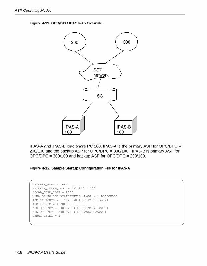
Figure 4-11. OPC/DPC IPAS with Override
IPAS-A and IPAS-B load share PC 100. IPAS-A is the primary ASP for OPC/DPC = 200/100 and the backup ASP for OPC/DPC = 300/100. IPAS-B is primary ASP for OPC/DPC = 300/100 and backup ASP for OPC/DPC = 200/100.
Figure 4-12. Sample Startup Configuration File for IPAS-A
GATEWAY_MODE = IPASPRIMARY_LOCAL_HOST = 192.168.1.100LOCAL_SCTP_PORT = 2905M3UA_SG_TO_SGP_DISTRIBUTION_MODE = 1 LOADSHAREADD_IP_ROUTE = 1 192.168.1.50 2905 route1ADD_IP_CPC = 1 200 300ADD_OPC_KEY = 200 OVERRIDE_PRIMARY 1000 1ADD_OPC_KEY = 300 OVERRIDE_BACKUP 2000 1DEBUG_LEVEL = 1
200
SS7 network
SG
IPAS-A 100
IPAS-B 100
300
4-18 SINAP/IP User’s Guide

ASP Operating Modes
Figure 4-13. Sample Startup Configuration File for IPAS-B
• ADD_OPC_KEY = 200 OVERRIDE_PRIMARY 1000 1
• 200 is the remote OPC.
• OVERRIDE_PRIMARY means traffic mode is OVERRIDE and this ASP is the primary ASP.
• 1000 is the routing context.
N O T E
The routing context must match with the one configured at the SG.
• 1 is the associated SG ID.
• ADD_OPC_KEY = 300 OVERRIDE_BACKUP 2000 1
• 300 is the remote OPC
• OVERRIDE_BACKUP means traffic mode is OVERRIDE and this ASP is the backup ASP.
• 2000 is the routing context.
• 1 is the associated SG ID.
During normal operation, IPAS-A and IPAS-B load share PC 100 so that all messages that originate from PC 200 are routed to IPAS-A and all messages that originate from PC 300 are routed to IPAS-B. If IPAS-A goes down, IPAS-B takes over all traffic from OPC 200 and 300 to DPC 100. The same applies to IPAS-A when IPAS-B does down. Since one ASP is active at a time, TC-BEGIN or TC-CONTINUE messages are guaranteed to be routed back to the originating ASP.
GATEWAY_MODE = IPASPRIMARY_LOCAL_HOST = 192.168.1.101LOCAL_SCTP_PORT = 2905M3UA_SG_TO_SGP_DISTRIBUTION_MODE = 1 LOADSHAREADD_IP_ROUTE = 1 192.168.1.50 2905 route1ADD_IP_CPC = 1 200 300ADD_OPC_KEY = 200 OVERRIDE_BACKUP 1000 1ADD_OPC_KEY = 300 OVERRIDE_PRIMARY 2000 1DEBUG_LEVEL = 1
ASP Mode 4-19
ASP Operating Modes
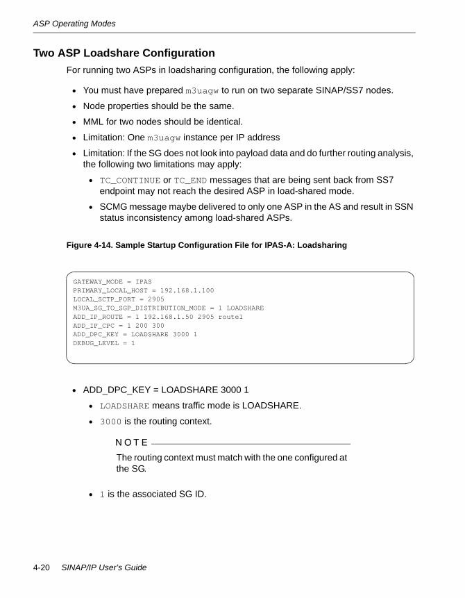
Two ASP Loadshare ConfigurationFor running two ASPs in loadsharing configuration, the following apply:
• You must have prepared m3uagw to run on two separate SINAP/SS7 nodes.
• Node properties should be the same.
• MML for two nodes should be identical.
• Limitation: One m3uagw instance per IP address
• Limitation: If the SG does not look into payload data and do further routing analysis, the following two limitations may apply:
• TC_CONTINUE or TC_END messages that are being sent back from SS7 endpoint may not reach the desired ASP in load-shared mode.
• SCMG message maybe delivered to only one ASP in the AS and result in SSN status inconsistency among load-shared ASPs.
Figure 4-14. Sample Startup Configuration File for IPAS-A: Loadsharing
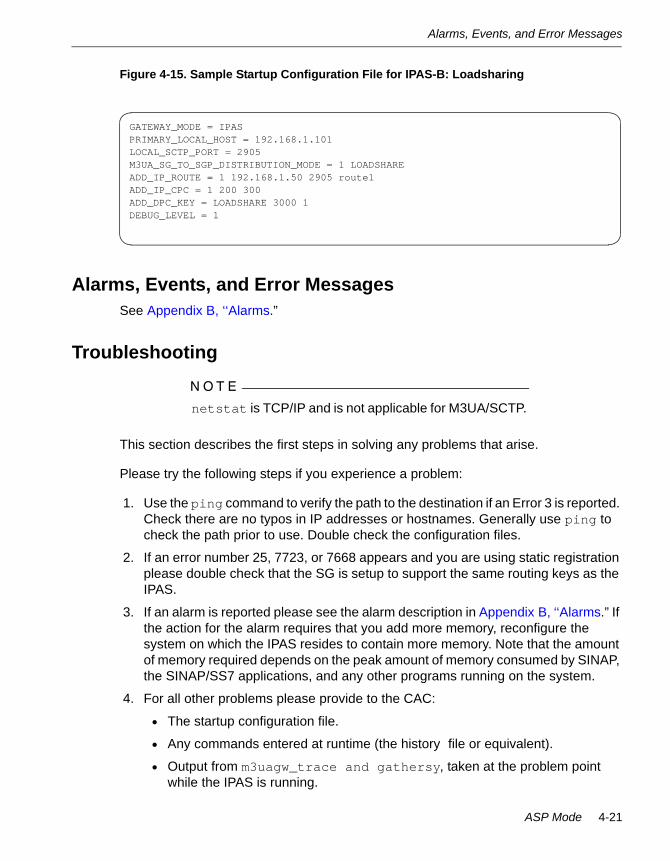
• ADD_DPC_KEY = LOADSHARE 3000 1
• LOADSHARE means traffic mode is LOADSHARE.
• 3000 is the routing context.
N O T E
The routing context must match with the one configured at the SG.
• 1 is the associated SG ID.
GATEWAY_MODE = IPASPRIMARY_LOCAL_HOST = 192.168.1.100LOCAL_SCTP_PORT = 2905M3UA_SG_TO_SGP_DISTRIBUTION_MODE = 1 LOADSHAREADD_IP_ROUTE = 1 192.168.1.50 2905 route1ADD_IP_CPC = 1 200 300ADD_DPC_KEY = LOADSHARE 3000 1DEBUG_LEVEL = 1
4-20 SINAP/IP User’s Guide
Alarms, Events, and Error Messages
Figure 4-15. Sample Startup Configuration File for IPAS-B: Loadsharing
Alarms, Events, and Error MessagesSee Appendix B, ‘‘Alarms.”
Troubleshooting
N O T E
netstat is TCP/IP and is not applicable for M3UA/SCTP.
This section describes the first steps in solving any problems that arise.
Please try the following steps if you experience a problem:
1. Use the ping command to verify the path to the destination if an Error 3 is reported. Check there are no typos in IP addresses or hostnames. Generally use ping to check the path prior to use. Double check the configuration files.
2. If an error number 25, 7723, or 7668 appears and you are using static registration please double check that the SG is setup to support the same routing keys as the IPAS.
3. If an alarm is reported please see the alarm description in Appendix B, ‘‘Alarms.” If the action for the alarm requires that you add more memory, reconfigure the system on which the IPAS resides to contain more memory. Note that the amount of memory required depends on the peak amount of memory consumed by SINAP, the SINAP/SS7 applications, and any other programs running on the system.
4. For all other problems please provide to the CAC:
• The startup configuration file.
• Any commands entered at runtime (the history file or equivalent).
• Output from m3uagw_trace and gathersy, taken at the problem point while the IPAS is running.
GATEWAY_MODE = IPASPRIMARY_LOCAL_HOST = 192.168.1.101LOCAL_SCTP_PORT = 2905M3UA_SG_TO_SGP_DISTRIBUTION_MODE = 1 LOADSHAREADD_IP_ROUTE = 1 192.168.1.50 2905 route1ADD_IP_CPC = 1 200 300ADD_DPC_KEY = LOADSHARE 3000 1DEBUG_LEVEL = 1
ASP Mode 4-21

Troubleshooting
• The problem display from STDOUT or a user-specified file with DEBUG_LEVEL = 1. Greater verbosity may be requested by the CAC.
• SINAP Alarm Log (preferably in ASCII form). Note that alarms in this log are prefixed with M3UAGW.
• DISPLAY_IP_CPC outputs.
• Core files from any core dumps.
4-22 SINAP/IP User’s Guide

Chapter 5IPSP Mode5-
IPAS IPSP ModeSINAP/IP supports the IPSP configuration, with the following properties:
• IPAS point-to-point communication without an SG router in between
• Each end point acting as an ASP talking to one or more remote ASP(s)
• Supporting override, broadcast, and loadshare modes
Figure 5-1 shows the basic configuration for SINAP/IP configured as an IPSP.
Figure 5-1. SINAP/IP IPSP Basic Configuration
N O T E
Use an IP router if the IPSP systems are on different subnets; but if the systems are all on the same subnet (broadcast domain), an Ethernet switch or hub can be used instead.
ftServer
IP Router
SINAPSINAPIPASIPAS
ftServer
IP IP
IP Routing FunctionIPSP Client IPSP Server
SINAPSINAPIPASIPAS
IPSP Mode 5-1

ITU Software Configuration
ITU Software ConfigurationFigure 5-2 Show a sample minimal configuration for an ITU (CCITT) IPSP.
Figure 5-2. Sample ITU IPSP Configuration
N O T E
Use an IP router if the IPSP systems are on different subnets, but if the systems are all on the same subnet (broadcast domain) an Ethernet switch or hub can be used instead.
Minimal IPSP Startup File Examples for ITUThe following startup files are typical startup files that are supplied solely for demonstration purposes. A complete description of each command is provided in Chapter 6, ‘‘Command Reference”.
Figure 5-3. IPSP ITU Client Startup Configuration File - Dynamic Registration
DYNAMIC_REGISTRATIONGATEWAY_MODE = IPASPRIMARY_LOCAL_HOST = 192.168.1.100LOCAL_SCTP_PORT = 2905ADD_IP_ROUTE = 192.168.1.101 2905 route1DEBUG_LEVEL = 1
PC=2665
SINAP Driver
IPAS c
PC=2669
SINAP DriverIP
Tra
ffic
tcrecvSSN=2
tcsendSSN=2IP
Router
IP T
raffi
c
IPAS s
5-2 SINAP/IP User’s Guide

ITU Software Configuration
Figure 5-4. IPSP ITU Server Startup Configuration File - Dynamic Registration
Figure 5-5. IPSP ITU Client Startup Configuration File - Static Registration
Figure 5-6. IPSP ITU Server Startup Configuration File - Static Registration
In these samples, the following entries are used:
• IS_SERVER. Indicates that the gateway acts as an IPSP server.
• If not present, the gateway acts as an IPSP client.
• The connection is always initiated from the client side.
IS_SERVERDYNAMIC_REGISTRATIONGATEWAY_MODE = IPASPRIMARY_LOCAL_HOST = 192.168.1.101LOCAL_SCTP_PORT = 2905ADD_IP_ROUTE = 192.168.1.100 2905 route1DEBUG_LEVEL = 1
GATEWAY_MODE = IPASPRIMARY_LOCAL_HOST = 192.168.1.100LOCAL_SCTP_PORT = 2905ADD_IP_ROUTE = 192.168.1.101 2905 route1ADD_LOCAL_KEY = PARTIAL LOADSHARE 1000ADD_REMOTE_KEY = 2669 PARTIAL 2000 route1DEBUG_LEVEL = 1
IS_SERVERGATEWAY_MODE = IPASPRIMARY_LOCAL_HOST = 192.168.1.101LOCAL_SCTP_PORT = 2905ADD_IP_ROUTE = 192.168.1.100 2905 route1DEBUG_LEVEL = 1ADD_LOCAL_KEY = PARTIAL LOADSHARE 2000ADD_REMOTE_KEY = 2665 PARTIAL 1000 route1
IPSP Mode 5-3
ITU Software Configuration
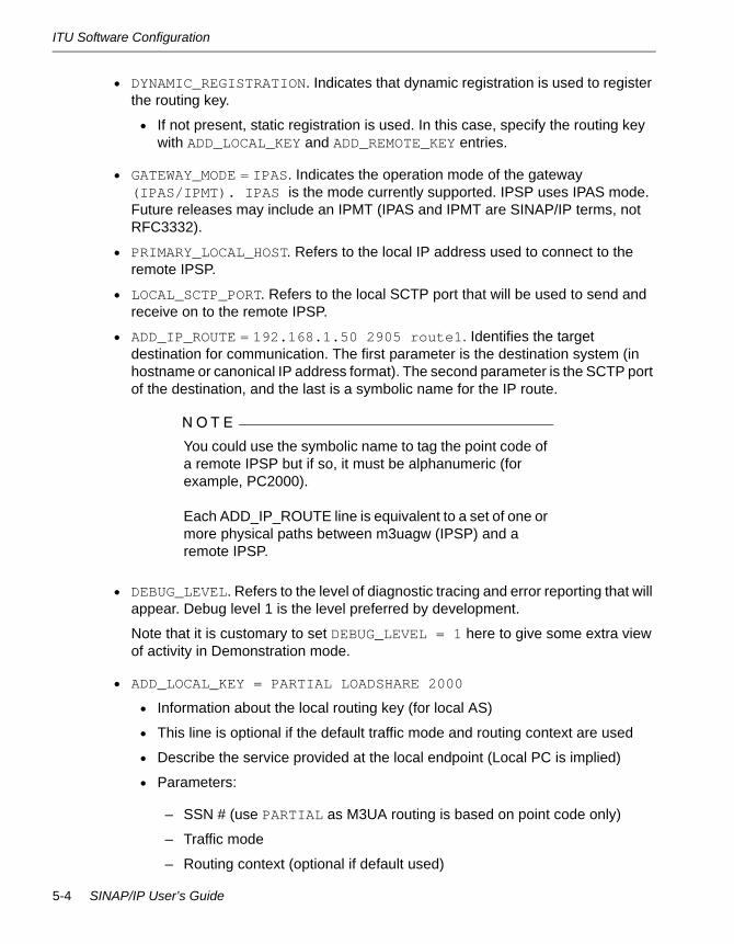
• DYNAMIC_REGISTRATION. Indicates that dynamic registration is used to register the routing key.
• If not present, static registration is used. In this case, specify the routing key with ADD_LOCAL_KEY and ADD_REMOTE_KEY entries.
• GATEWAY_MODE = IPAS. Indicates the operation mode of the gateway (IPAS/IPMT). IPAS is the mode currently supported. IPSP uses IPAS mode. Future releases may include an IPMT (IPAS and IPMT are SINAP/IP terms, not RFC3332).
• PRIMARY_LOCAL_HOST. Refers to the local IP address used to connect to the remote IPSP.
• LOCAL_SCTP_PORT. Refers to the local SCTP port that will be used to send and receive on to the remote IPSP.
• ADD_IP_ROUTE = 192.168.1.50 2905 route1. Identifies the target destination for communication. The first parameter is the destination system (in hostname or canonical IP address format). The second parameter is the SCTP port of the destination, and the last is a symbolic name for the IP route.
N O T E
You could use the symbolic name to tag the point code of a remote IPSP but if so, it must be alphanumeric (for example, PC2000).
Each ADD_IP_ROUTE line is equivalent to a set of one or more physical paths between m3uagw (IPSP) and a remote IPSP.
• DEBUG_LEVEL. Refers to the level of diagnostic tracing and error reporting that will appear. Debug level 1 is the level preferred by development.
Note that it is customary to set DEBUG_LEVEL = 1 here to give some extra view of activity in Demonstration mode.
• ADD_LOCAL_KEY = PARTIAL LOADSHARE 2000
• Information about the local routing key (for local AS)
• This line is optional if the default traffic mode and routing context are used
• Describe the service provided at the local endpoint (Local PC is implied)
• Parameters:
– SSN # (use PARTIAL as M3UA routing is based on point code only)
– Traffic mode
– Routing context (optional if default used)
5-4 SINAP/IP User’s Guide

ITU Software Configuration
• ADD_REMOTE_KEY = 2665 PARTIAL 1000 route1
• Information about the remote routing key (for remote AS)
• Describes the service provided at the remote endpoint
• Parameters:
– Point code (use x-x-x format if ANSI)
– SSN # (use PARTIAL as M3UA routing is based on point code only)
– Routing context (optional if default value is used)
– Name of the route used by this remote key
ITU MMLAs with SINAP/SS7, MML must be set up correctly at the SINAP/SS7 node where the IPSP is to be run.
See the SINAP/SS7 User’s Guide (R8051) for information on MML commands.
Figure 5-7 is an example for ITU, International Network (INAT00). It is necessary to configure and activate fake routesets, linksets, and a link (create only). There can be installed or active SS7 links at the node where the IPAS runs, but the fake link for IPAS must be on a port that does not exist in the SS7links file for that node.
The remote SSNs and CPCs must be identified correctly.
Figure 5-7 shows the example SINAP/SS7 ITU MML for the IPSP client node. Note the dummy PORTNUM=0 used to create the fake link for IPAS traffic.
Figure 5-7. IPSP Client Node ITU MML
CREATE-OSP:NETWORK=INAT00,SPC=2665;CREATE-LSET:LINKSET=LSET1,ADPC=2669,LOADLINK=1,ACTLINK=1;CREATE-LINK:LINK=LNK0,PORTNUM=0,LINKSET=LSET1,SLC=0,PRIORITY=0,SPEED=0;CREATE-RSET:ROUTESET=RSET1,DPC=2669,ROUTES=LSET1,LOADSHR=ENABLE;CREATE-CPC:LSSN=2,RPC=2669;CREATE-REMSSN:PC=2669,SSN=2;CONFIGURE-LSET:LINKSET=LSET1,STATE=ACTIVE;CONFIGURE-RSET:ROUTESET=RSET1,STATE=ACTIVE;
IPSP Mode 5-5

ANSI Software Configuration
Figure 5-8 shows the example SINAP/SS7 ITU MML for the server node.
Figure 5-8. IPSP Server Node ITU MML
ANSI Software ConfigurationFigure 5-9 Show a sample minimal configuration for an ANSI IPSP.
Figure 5-9. Sample ANSI IPSP Configuration
N O T E
Use an IP router if the IPSP systems are on different subnets, but if the systems are all on the same subnet (broadcast domain) an Ethernet switch or hub can be used instead.
CREATE-OSP:NETWORK=INAT00,SPC=2669;CREATE-LSET:LINKSET=LSET1,ADPC=2665,LOADLINK=1,ACTLINK=1;CREATE-LINK:LINK=LNK0,PORTNUM=0,LINKSET=LSET1,SLC=0,PRIORITY=0,SPEED=0;CREATE-RSET:ROUTESET=RSET1,DPC=2665,ROUTES=LSET1,LOADSHR=ENABLE;CREATE-CPC:LSSN=2,RPC=2995;CREATE-REMSSN:PC=2665,SSN=2;CONFIGURE-LSET:LINKSET=LSET1,STATE=ACTIVE;CONFIGURE-RSET:ROUTESET=RSET1,STATE=ACTIVE;
PC=2-2-2
SINAP Driver
IPAS c
PC=4-4-4
SINAP Driver
IP T
raffi
c
tcrecvSSN=2
tcsendSSN=2IP
Router
IP T
raffi
c
IPAS s
5-6 SINAP/IP User’s Guide

ANSI Software Configuration
IPSP Startup File for ANSIThe ANSI IPSP startup file for dynamic registration is the same as that for ITU. See ‘‘Minimal IPSP Startup File Examples for ITU.” For static registration, the only difference from ITU is the point code format (use ANSI x-x-x) for ADD_LOCAL_KEY and ADD_REMOTE_KEY.
ANSI MMLAs with SINAP/SS7, MML must be set up correctly at the SINAP/SS7 node where the IPSP is to be run.
See the SINAP/SS7 User’s Guide (R8051) for information on MML commands.
Figure 5-10 is an example for ANSI, National Network (NAT10). It is necessary to configure and activate fake routesets, linksets, and a link (create only). There can be installed or active SS7 links at the node where the IPAS runs, but the fake link for IPAS must be on a port that does not exist in the SS7links file for that node.
The remote SSNs and CPCs must be identified correctly.
Figure 5-10 shows the example SINAP/SS7 ANSI MML for the IPSP client node. Note the dummy PORTNUM=0 used to create the fake link for IPAS traffic.
Figure 5-10. IPSP Client Node ANSI MML
Figure 5-11 shows the example SINAP/SS7 ANSI MML for the IPSP server node.
CREATE-OSP:NETWORK=NAT10,SPC=2-2-2;CREATE-LSET:LINKSET=LSET1,ADPC=4-4-4,TYPE=F,LOADLINK=1,ACTLINK=1;CREATE-LINK:LINK=LNK0,PORTNUM=0,LINKSET=LSET1,SLC=0,PRIORITY=0,SPEED=0;CREATE-RSET:ROUTESET=RSET1,DPC=4-4-4,ROUTES=LSET1;CREATE-CPC:LSSN=2,RPC=4-4-4;CREATE-REMSSN:PC=4-4-4,SSN=2;CONFIGURE-LSET:LINKSET=LSET1,STATE=ACTIVE;CONFIGURE-RSET:ROUTESET=RSET1,STATE=ACTIVE;
IPSP Mode 5-7

Operation and Maintenance
Figure 5-11. IPSP Server Node ANSI MML
Operation and MaintenanceThis section describes operation and maintenance for the IPSP system. It includes the following sections about the essential IPSP on-line management operations:
The following sections describe the essential IPSP operations:
• ‘‘Add a New IPSP Endpoint - Dynamic Registration”
• ‘‘Delete an Existing IPSP Endpoint - Dynamic Registration”
• ‘‘Add a New IPSP Endpoint - Static Registration”
• ‘‘Delete an Existing IPSP Endpoint - Static Registration”
• ‘‘Display Routing Key Information”
Add a New IPSP Endpoint - Dynamic Registration1. Decide whether the node should be an IPSP server or an IPSP client, based on the
role of the existing IPSP endpoint it needs to interoperate with.
2. At the IPSP server, use the ADD_IP_ROUTE command to add a route to the IPSP client.The server will then wait for new client connection.
3. At the IPSP client, use the ADD_IP_ROUTE command to add a new route to the IPSP server. A connection attempt will be made immediately to the IPSP server after the ADD_IP_ROUTE command is issued.
Traffic should be able to go through after the connection is up and the endpoints are active. If the SCCP subsystem state is not allowed, make sure that the SST and SSA messages are exchanged before TCAP traffic starts.
CREATE-OSP:NETWORK=NAT10,SPC=4-4-4;CREATE-LSET:LINKSET=LSET1,ADPC=2-2-2,TYPE=F,LOADLINK=1,ACTLINK=1;CREATE-LINK:LINK=LNK0,PORTNUM=0,LINKSET=LSET1,SLC=0,PRIORITY=0,SPEED=0;CREATE-RSET:ROUTESET=RSET1,DPC=2-2-2,ROUTES=LSET1;CREATE-CPC:LSSN=2,RPC=2-2-2;CREATE-REMSSN:PC=2-2-2,SSN=2;CONFIGURE-LSET:LINKSET=LSET1,STATE=ACTIVE;CONFIGURE-RSET:ROUTESET=RSET1,STATE=ACTIVE;
5-8 SINAP/IP User’s Guide
Operation and Maintenance
Delete an Existing IPSP Endpoint - Dynamic Registration1. Stop application traffic to the involved endpoints if possible.
2. At the IPSP client, use the PROHIBIT_TRAFFIC_ON_ROUTE command to prohibit traffic-sending from the route to the IPSP server.
3. At the IPSP server, use the PROHIBIT_TRAFFIC_ON_ROUTE command to prohibit traffic-sending from the route to the IPSP client.
4. Make sure that all traffic is stopped and endpoints are prohibited before going further.
5. At the IPSP client, use the DELETE_IP_ROUTE command to delete the route to the IPSP server.
N O T E
This step, at the client, must be done before step 6, at the server.
6. At the IPSP server, use the DELETE_IP_ROUTE command to delete the route to the IPSP client.
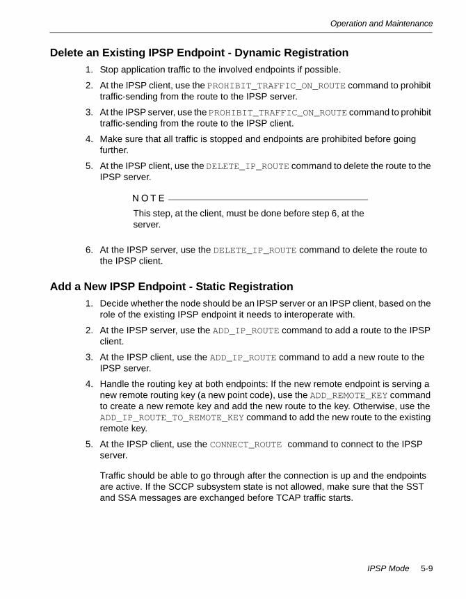
Add a New IPSP Endpoint - Static Registration1. Decide whether the node should be an IPSP server or an IPSP client, based on the
role of the existing IPSP endpoint it needs to interoperate with.
2. At the IPSP server, use the ADD_IP_ROUTE command to add a route to the IPSP client.
3. At the IPSP client, use the ADD_IP_ROUTE command to add a new route to the IPSP server.
4. Handle the routing key at both endpoints: If the new remote endpoint is serving a new remote routing key (a new point code), use the ADD_REMOTE_KEY command to create a new remote key and add the new route to the key. Otherwise, use the ADD_IP_ROUTE_TO_REMOTE_KEY command to add the new route to the existing remote key.
5. At the IPSP client, use the CONNECT_ROUTE command to connect to the IPSP server.
Traffic should be able to go through after the connection is up and the endpoints are active. If the SCCP subsystem state is not allowed, make sure that the SST and SSA messages are exchanged before TCAP traffic starts.
IPSP Mode 5-9
Operation and Maintenance
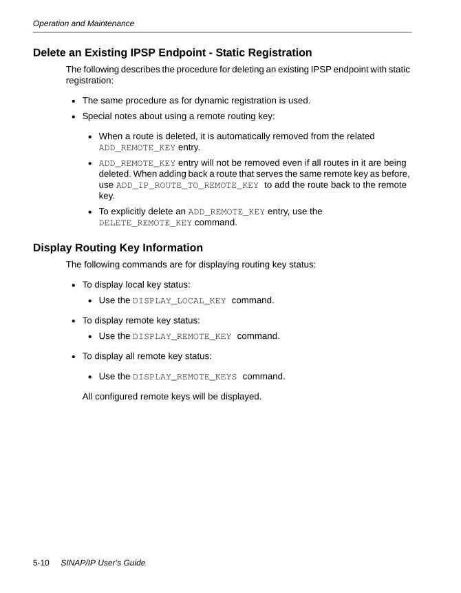
Delete an Existing IPSP Endpoint - Static RegistrationThe following describes the procedure for deleting an existing IPSP endpoint with static registration:
• The same procedure as for dynamic registration is used.
• Special notes about using a remote routing key:
• When a route is deleted, it is automatically removed from the related ADD_REMOTE_KEY entry.
• ADD_REMOTE_KEY entry will not be removed even if all routes in it are being deleted. When adding back a route that serves the same remote key as before, use ADD_IP_ROUTE_TO_REMOTE_KEY to add the route back to the remote key.
• To explicitly delete an ADD_REMOTE_KEY entry, use the DELETE_REMOTE_KEY command.
Display Routing Key InformationThe following commands are for displaying routing key status:
• To display local key status:
• Use the DISPLAY_LOCAL_KEY command.
• To display remote key status:
• Use the DISPLAY_REMOTE_KEY command.
• To display all remote key status:
• Use the DISPLAY_REMOTE_KEYS command.
All configured remote keys will be displayed.
5-10 SINAP/IP User’s Guide

M3UAGW IPSP Commands
M3UAGW IPSP CommandsThe following table summarizes the M3UAGW IPSP commands.
Command Name Startup or Runtime
Mandatory or Optional
ADD_IP_ROUTE Both Mandatory
ADD_IP_ROUTE_TO_REMOTE_KEY Runtime Optional
ADD_LOCAL_KEY Both Optional
ADD_REMOTE_KEY Both Optional
ALLOW_TRAFFIC_ON_ROUTE Runtime Optional
CONNECT_ROUTE Both Optional
DEBUG_LEVEL Both Optional
DELETE_IP_ROUTE Runtime Optional
DELETE_REMOTE_KEY Runtime Optional
DISABLE_STATISTICS_FOR_NODE Runtime Optional
DISABLE_STATISTICS_ON_ROUTES Runtime Optional
DISPLAY_GATEWAY_VERSION Runtime Optional
DISPLAY_IP_ROUTE Runtime Optional
DISPLAY_LOCAL_KEY Runtime Optional
DISPLAY_LOCAL_KEYS Runtime Optional
DISPLAY_REMOTE_KEY Runtime Optional
DISPLAY_REMOTE_KEYS Runtime Optional
DISPLAY_STATISTICS_FOR_NODE Runtime Optional
DISPLAY_STATISTICS_FOR_ROUTE Runtime Optional
DISPLAY_SCTP_PARAMETERS Both Optional
DYNAMIC_REGISTRATION Startup Optional
ENABLE_M3UA_TRACE Both Optional
ENABLE_SCTP_TRACE Both Optional
ENABLE_STATISTICS_FOR NODE Both Optional
IPSP Mode 5-11

M3UAGW IPSP Commands
ENABLE_STATISTICS_ON_ROUTES Both Optional
GATEWAY_MODE Startup Mandatory
INITIAL_TRAFFIC_STATE Startup Optional
IS_SERVER Startup Optional
LOCAL_SCTP_PORT Startup Mandatory
M3UA_AUDIT_TIMER Startup Optional
M3UA_CONGESTION_TIMER Startup Optional
M3UA_MAX_RETRANSMISSIONS Startup Optional
M3UA_RETRANSMISSION_TIME Startup Optional
M3UA_SWITCHOVER_COUNT Startup Optional
OUTPUT_FILE Startup Optional
PRIMARY_LOCAL_HOST Startup Mandatory
PROHIBIT_TRAFFIC_ON_ROUTE Runtime Optional
RECONNECT_TIMER Both Optional
RUN_TIME_CMD_FILE Startup Optional
SCTP_ASSOC_MAX_RETRANS Both Optional
SCTP_BUNDLING_TIME Both Optional
SCTP_FRAGMENTATION_ALLOWED Both Optional
SCTP_HEARTBEAT Both Optional
SCTP_HIGH_CONG_LEVEL Both Optional
SCTP_LOW_CONG_LEVEL Both Optional
SCTP_MAX_ENDPOINTS Startup Optional
SCTP_MAX_RX_BUFFERS Startup Optional
SCTP_MAX_TX_BUFFERS Startup Optional
SCTP_NO_CONG_LEVEL Both Optional
SCTP_PATH_MAX_RETRANS Both Optional
Command Name Startup or Runtime
Mandatory or Optional
5-12 SINAP/IP User’s Guide
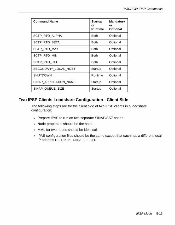
M3UAGW IPSP Commands
Two IPSP Clients Loadshare Configuration - Client SideThe following steps are for the client side of two IPSP clients in a loadshare configuration:
• Prepare IPAS to run on two separate SINAP/SS7 nodes.
• Node properties should be the same.
• MML for two nodes should be identical.
• IPAS configuration files should be the same except that each has a different local IP address (PRIMARY_LOCAL_HOST).
SCTP_RTO_ALPHA Both Optional
SCTP_RTO_BETA Both Optional
SCTP_RTO_MAX Both Optional
SCTP_RTO_MIN Both Optional
SCTP_RTO_INIT Both Optional
SECONDARY_LOCAL_HOST Startup Optional
SHUTDOWN Runtime Optional
SINAP_APPLICATION_NAME Startup Optional
SINAP_QUEUE_SIZE Startup Optional
Command Name Startup or Runtime
Mandatory or Optional
IPSP Mode 5-13
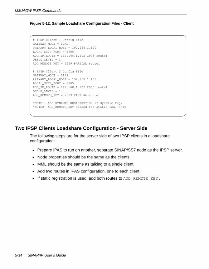
M3UAGW IPSP Commands
Figure 5-12. Sample Loadshare Configuration Files - Client
Two IPSP Clients Loadshare Configuration - Server SideThe following steps are for the server side of two IPSP clients in a loadshare configuration:
• Prepare IPAS to run on another, separate SINAP/SS7 node as the IPSP server.
• Node properties should be the same as the clients.
• MML should be the same as talking to a single client.
• Add two routes in IPAS configuration, one to each client.
• If static registration is used, add both routes to ADD_REMOTE_KEY.
# IPSP Client 1 Config FileGATEWAY_MODE = IPASPRIMARY_LOCAL_HOST = 192.168.1.100LOCAL_SCTP_PORT = 2905ADD_IP_ROUTE = 192.168.1.102 2905 route1DEBUG_LEVEL = 1ADD_REMOTE_KEY = 2669 PARTIAL route1
# IPSP Client 2 Config FileGATEWAY_MODE = IPASPRIMARY_LOCAL_HOST = 192.168.1.101LOCAL_SCTP_PORT = 2905ADD_IP_ROUTE = 192.168.1.102 2905 route1DEBUG_LEVEL = 1ADD_REMOTE_KEY = 2669 PARTIAL route1
*NOTE1: Add DYNAMIC_REGISTARTION if dynamic reg.*NOTE2: ADD_REMOTE_KEY needed for static reg. only
5-14 SINAP/IP User’s Guide

Alarms, Events, and Error Messages
Figure 5-13. Sample Loadshare Configuration File - Server
Alarms, Events, and Error MessagesSee Appendix B, ‘‘Alarms.”
Troubleshooting
N O T E
netstat is a TCP/IP command that is not applicable for troubleshooting M3UA/SCTP.
This section describes the first steps in solving any problems that arise.
Try the following steps if you experience a problem:
1. Use the ping command to verify the path to the destination if an Error 3 is reported. Make sure there are no typographical errors in IP addresses or hostnames. Generally use ping to check the path prior to use. Examine the configuration files for errors.
2. If an error number 25, 7723 or 7668 appears and you are using static registration, make sure that the SG is set up to support the same routing keys as the IPAS.
3. If an alarm is reported please the alarm description in Appendix B, ‘‘Alarms.” If the action for the alarm requires that you add more memory, reconfigure the system on which the IPAS resides to contain more memory. Note that the amount of memory required depends on the peak amount of memory consumed by SINAP/SS7, the SINAP/SS7 applications and any other programs running on the system.
# IPSP Server Config FileIS_SERVERGATEWAY_MODE = IPASPRIMARY_LOCAL_HOST = 192.168.1.102LOCAL_SCTP_PORT = 2905ADD_IP_ROUTE = 192.168.1.100 2905 route1ADD_IP_ROUTE = 192.168.1.101 2905 route2DEBUG_LEVEL = 1ADD_REMOTE_KEY = 2665 PARTIAL route1 route2
*NOTE1: Add DYNAMIC_REGISTARTION if dynamic reg.*NOTE2: ADD_REMOTE_KEY needed for static reg. only
IPSP Mode 5-15
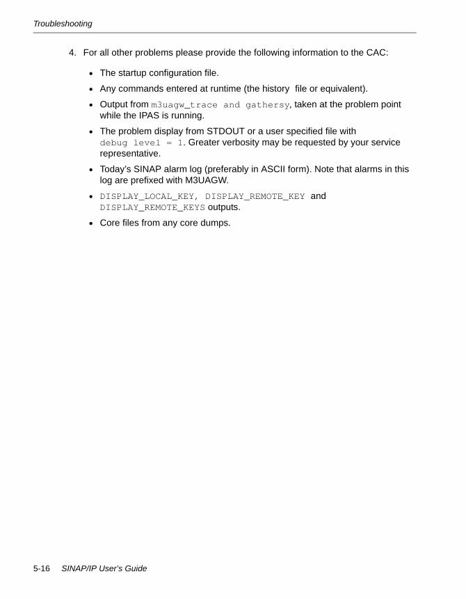
Troubleshooting
4. For all other problems please provide the following information to the CAC:
• The startup configuration file.
• Any commands entered at runtime (the history file or equivalent).
• Output from m3uagw_trace and gathersy, taken at the problem point while the IPAS is running.
• The problem display from STDOUT or a user specified file withdebug level = 1. Greater verbosity may be requested by your service representative.
• Today’s SINAP alarm log (preferably in ASCII form). Note that alarms in this log are prefixed with M3UAGW.
• DISPLAY_LOCAL_KEY, DISPLAY_REMOTE_KEY and DISPLAY_REMOTE_KEYS outputs.
• Core files from any core dumps.
5-16 SINAP/IP User’s Guide

Chapter 6Command Reference6-
This chapter describes the usage of executable files provided in the M3UAGW package, and the commands that can be entered through the command file or startup file to configure and/or manage the IPAS.
M3UAGW Executable CommandsThis section describes the usage of the following executable files provided in the M3UAGW package:
• m3uagw
• m3uagw_send_cm
• m3uagw_license_update
• m3uagw_trace
Command Reference 6-1
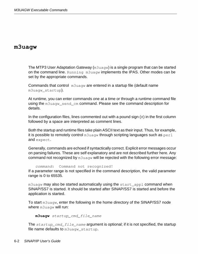
M3UAGW Executable Commands
m3uagw 6-
The MTP3 User Adaptation Gateway (m3uagw) is a single program that can be started on the command line. Running m3uagw implements the IPAS. Other modes can be set by the appropriate commands.
Commands that control m3uagw are entered in a startup file (default name m3uagw_startup).
At runtime, you can enter commands one at a time or through a runtime command file using the m3uagw_send_cm command. Please see the command description for details.
In the configuration files, lines commented out with a pound sign (#) in the first column followed by a space are interpreted as comment lines.
Both the startup and runtime files take plain ASCII text as their input. Thus, for example, it is possible to remotely control m3uagw through scripting languages such as perl and expect.
Generally, commands are echoed if syntactically correct. Explicit error messages occur on parsing failures. These are self explanatory and are not described further here. Any command not recognized by m3uagw will be rejected with the following error message:
command: Command not recognized!If a parameter range is not specified in the command description, the valid parameter range is 0 to 65535.
m3uagw may also be started automatically using the start_appl command when SINAP/SS7 is started. It should be started after SINAP/SS7 is started and before the application is started.
To start m3uagw, enter the following in the home directory of the SINAP/SS7 node where m3uagw will run:
m3uagw startup_cmd_file_name
The startup_cmd_file_name argument is optional; if it is not specified, the startup file name defaults to m3uagw_startup.
6-2 SINAP/IP User’s Guide
M3UAGW Executable Commands
When a user management command is executed successfully, the gateway saves the original command text, the execution status, and the time stamp to a history file. The history file is $SINAP_HOME/Logs/system/m3uagw_commands.log.
This file will not be erased by the gateway process, so that the history is preserved across a gateway restart. A time-stamped mark identifies the boundary of a gateway lifetime, however. If the file size becomes too large, you can manually empty its content.
By looking at the history file and the original startup file, you can manually reconstruct the latest running configuration. Consolidate any on-line change into the startup file, so that the gateway process can be restarted with the most up-to-date configuration. This is important especially for unplanned system shutdown.
Command Reference 6-3

M3UAGW Executable Commands
m3uagw_send_cm 6-
A user management client, m3uagw_send_cm, can feed one command to the gateway process by means of command line argument, or send a batch of commands written in a command flat file. The outputs or results returned from the gateway process are displayed on the client console. The following is the syntax:
m3uagw_send_cm [-s “command”] [-f file_name] [-h host] [-p port] [-v][-V]
The -s option sends a single command to the gateway process and displays the results, where “command” specifies the command to be executed. The client terminates after this single command invocation cycle. Type the quotation marks.
The -f option sends a batch of commands included in a command file, where file_name is the name of the file. The commands in the file will be sent to and executed by the gateway one at a time. The client maintains connection to the gateway process during the batch and displays results for each command. Any failure in the command execution will cause the client to terminate immediately with an error reason, thus the rest of the command will not be sent and executed.
The command file should include one command per line. Any empty line is ignored. A line started with a pound sign (#) will be treated as comment line and also ignored.
The -h option specifies the IP address or host name where the gateway process is running. If omitted, the default value 127.0.0.1 is used.
The -p option specifies the port number the gateway process is listening to handle the management connection. If omitted, the default port number 8655 is used.
The -v option turns on the verbose mode, where extra information about the client side's processing will be printed out to assist on diagnostics.
The -V option causes command line option usage to be displayed.
The client can be started on the same machine where the gateway process is running, or a remote machine that can reach the gateway process over the TCP/IP network. When running on a separate machine, the default address must be overridden using the -h option, and the gateway process must bind its management interface's listening
6-4 SINAP/IP User’s Guide
M3UAGW Executable Commands
address to its primary address using the BIND_UMI_TO_PRIMARY command in the startup configuration file (see below).
The gateway process will accept only one client connection at a time. If there is already an existing active client connection, any new client connection request will be rejected.
BIND_UMI_TO_PRIMARY and UMI_PORT = port_number are two new startup configuration commands for the gateway process. They can be used to change the default properties related to the management client-server connection.
• BIND_UMI_TO_PRIMARY
This command binds the user management interface's listening address at the gateway to gateway's primary address, i.e., the one specified in the PRIMARY_LOCAL_HOST command. If BIND_UMI_TO_PRIMARY is not used, by default it is bound to the local host address 127.0.0.1. If BIND_UMI_TO_PRIMARY is used, the m3uagw_send_cm command must use -h primary local host IP address in order to connect to the gateway process. For further information see USAGE GUIDELINES in the command descriptions.
• UMI_PORT = port_number
This command changes the user management interface's listening port at the gateway to port_number. If this command is not used, the default listening port 8655 is used. If UMI_PORT = port_number is used, the m3uagw_send_cm command must use -p port_number in order to connect to the gateway process. For further information, see USAGE GUIDELINES in the command descriptions.
Command Reference 6-5

M3UAGW Executable Commands
m3uagw_license_update 6-
This tool updates the license for SINAP/IP on-line without shutting down a running m3uagw process.
m3uagw_license_update is created and installed to the /Bin directory of the SINAP/SS7 node running m3uagw by /etc/config_m3uagw. This binary instructs all running m3uagw processes to update the license information according to the new license file.
After you receive the new IPAS license from Stratus, put the IPAS license in the existing license file (replacing the existing IPAS section), and perform the following tasks to bring the new license in effect:
1. Put the updated license file sinap.lic into /etc/sinap_license/ directory. Make sure there is only one file with a .lic extension in this directory.
2. In one SINAP/SS7 node with m3uagw running node (pick one node if multiple nodes are running m3uagw), invoke sinap_license_update to feed new license info to the running m3uagw processes, then inspect the log file for each running m3uagw process for update result. You do not need to restart SINAP/SS7 or the m3uagw process.
Please note that if no m3uagw is running on any node, then the second step is unnecessary because the new license will be in effect the next time m3uagw starts.
License verification will be done on the new license before the formal license update starts. Any error discovered in the new license will stop the updating process and m3uagw will keep running with its original license. Make sure to put the original license file back in /etc/sinap_license/ so that when m3uagw restarts, the original license file is used instead of the new one.
6-6 SINAP/IP User’s Guide

M3UAGW Executable Commands
m3uagw_trace 6-
m3uagw_trace is a tool used to display the tracing information of the running m3uagw process. It displays the version of the executable files, the operation mode of m3uagw, and the routing key status and histories.
m3uagw_trace takes no arguments. It must be used at the same node where m3uagw is being used, and will display information only when the m3uagw process is running.
See Figure 4-10 for a sample printout of the m3uagw_trace tool.
Command Reference 6-7

IPAS Commands
IPAS CommandsThis section describes the usage of the following IPAS commands and their operations:
ADD_DPC_KEY ENABLE_STATISTICS_ON_ROUTES
ADD_IP_CPC GATEWAY_MODE
ADD_IP_ROUTE INITIAL_TRAFFIC_STATE
ADD_IP_ROUTE_TO_REMOTE_KEY IS_SERVER
ADD_LOCAL_KEY LOCAL_SCTP_PORT
ADD_OPC_KEY M3UA_AUDIT_TIMER
ADD_REMOTE_KEY M3UA_CONGESTION_TIMER
ALLOW_TRAFFIC_ON_ROUTE M3UA_MAX_RETRANSMISSIONS
BIND_UMI_TO_PRIMARY M3UA_RETRANSMISSION_TIME
CONNECT_ROUTE M3UA_SG_TO_SGP_DISTRIBUTION_MODE
DEBUG_LEVEL M3UA_SWITCHOVER_COUNT
DELETE_IP_CPC OUTPUT_FILE
DELETE_IP_ROUTE PRIMARY_LOCAL_HOST
DELETE_REMOTE_KEY PROHIBIT_TRAFFIC_ON_ROUTE
DISABLE_STATISTICS_FOR_NODE RECONNECT_TIMER
DISABLE_STATISTICS_ON_ROUTES SCTP_ASSOC_MAX_RETRANS
DISPLAY_GATEWAY_VERSION SCTP_BUNDLING_TIME
DISPLAY_IP_CPCS SCTP_FRAGMENTATION_ALLOWED
DISPLAY_IP_ROUTE SCTP_HEARTBEAT
DISPLAY_LOCAL_KEY = SCTP_HIGH_CONG_LEVEL
DISPLAY_IP_CPCS SCTP_LOW_CONG_LEVEL
DISPLAY_IP_CPCS SCTP_MAX_ENDPOINTS
DISPLAY_IP_CPCS SCTP_MAX_RX_BUFFERS
DISPLAY_IP_CPCS SCTP_MAX_TX_BUFFERS
DISPLAY_IP_ROUTE SCTP_NO_CONG_LEVEL
DISPLAY_LOCAL_KEY = SCTP_PATH_MAX_RETRANS
DISPLAY_LOCAL_KEY SCTP_RTO_ALPHA
DISPLAY_LOCAL_KEYS SCTP_RTO_BETA
DISPLAY_REMOTE_KEY SCTP_RTO_INIT
DISPLAY_REMOTE_KEYS SCTP_RTO_MAX
DISPLAY_STATISTICS_FOR_NODE SCTP_RTO_MIN
6-8 SINAP/IP User’s Guide

IPAS Commands
N O T E
In the command descriptions, the vertical bar (|) indicates exclusive OR.
DISPLAY_STATISTICS_FOR_ROUTE SCTP_RTO_INIT
DISPLAY_SCTP_PARAMETERS SHUTDOWN
DYNAMIC_REGISTRATION SINAP_APPLICATION_NAME
ENABLE_M3UA_TRACE SINAP_QUEUE_SIZE
ENABLE_SCTP_TRACE UMI_PORT
ENABLE_STATISTICS_FOR_NODE
Command Reference 6-9

IPAS Commands
ADD_DPC_KEY 6-
Create a DPC based routing key.
ADD_DPC_KEY = traffic mode routing context list_of_SG_IDs
PARAMETERStraffic mode
One of the following values:
LOADSHAREBROADCASTOVERRIDE_PRIMARYOVERRIDE_BACKUP
See ‘‘ASP Operating Modes’’ on page 4-17.
routing context The numeric value associated with the routing key.
N O T E
The routing context must match the one configured at the SG.
list of SG IDs A valid SG ID is a numeric value between 0 and 15 (0 <= SG ID <= 15). If the DPC key is serviced by more than one SG, list all the SG IDs here.
DEFAULTSNo default behavior or value.
OPERATION CONDITIONASP.
OPERATION MODEStartup.
6-10 SINAP/IP User’s Guide

IPAS Commands
USAGE GUIDELINESWhen registering m3uagw to the M3UA stack, the DPC is fixed to the SINAP/SS7 PC of the IPAS. The IPAS supports multiple SGs. In OVERRIDE traffic mode, configure only one primary ASP. You can configure multiple backup ASPs.
Command Reference 6-11

IPAS Commands
ADD_IP_CPC 6-
Add one or multiple concerned point code to the SG.
ADD_IP_CPC = sg_id cpc...
PARAMETERSsg_id
The identification number of the SG. The sg_id is defined by the following command
M3UA_SG_TO_SGP_DISTRIBUTION_MODE
cpc The concerned point code served by the SG. You can enter multiple codes, separated by spaces.
DEFAULTSNo default behavior or value.
OPERATION MODEASP.
OPERATION CONDITIONStartup and runtime.
USAGE GUIDELINESAfter an SG is created, the ADD_IP_CPC command adds a concerned point code to the SG, so messages destined to the concerned point code can be routed to the SG that serves it.
6-12 SINAP/IP User’s Guide
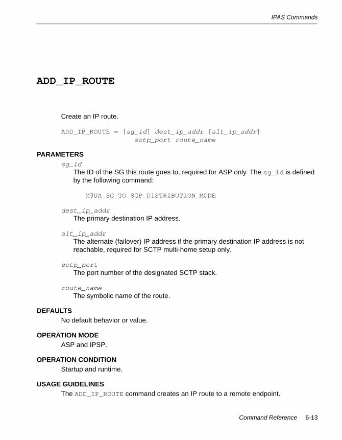
IPAS Commands
ADD_IP_ROUTE 6-
Create an IP route.
ADD_IP_ROUTE = [sg_id] dest_ip_addr [alt_ip_addr]sctp_port route_name
PARAMETERSsg_id
The ID of the SG this route goes to, required for ASP only. The sg_id is defined by the following command:
M3UA_SG_TO_SGP_DISTRIBUTION_MODE
dest_ip_addr The primary destination IP address.
alt_ip_addr The alternate (failover) IP address if the primary destination IP address is not reachable, required for SCTP multi-home setup only.
sctp_port The port number of the designated SCTP stack.
route_name The symbolic name of the route.
DEFAULTSNo default behavior or value.
OPERATION MODEASP and IPSP.
OPERATION CONDITIONStartup and runtime.
USAGE GUIDELINESThe ADD_IP_ROUTE command creates an IP route to a remote endpoint.
Command Reference 6-13
IPAS Commands
In ASP mode, the remote endpoint is an SGP. An SG ID is required for the route.
In IPSP mode, the remote endpoint is a remote IPSP. An SG ID is not needed, and should thus be omitted.
If SCTP multi-home setup is used, the second IP address (alt_ip_addr) should be specified. It is used as the failover destination address. In this case, both PRIMARY_LOCAL_HOST and SECONDARY_LOCAL_HOST need to be specified as well.
6-14 SINAP/IP User’s Guide

IPAS Commands
ADD_IP_ROUTE_TO_REMOTE_KEY 6-
Add an IP route to the remote routing key.
ADD_IP_ROUTE_TO_REMOTE_KEY = pc [ssn | PARTIAL] route_name
PARAMETERSpc
The point code of the remote key.
ssn The service subsystem number (SSN) of the remote key. Since SSN routing is not supported by M3UA, always use PARTIAL here to indicate a partial key. Routing will then be based on the point code only.
route_name
The symbolic name of the IP route.
DEFAULTSNo default behavior or value.
OPERATION MODEIPSP.
OPERATION CONDITIONRuntime.
USAGE GUIDELINESAfter a remote routing key is created, the ADD_IP_ROUTE_TO_REMOTE_KEY command adds an IP route to the remote key at runtime, so that messages destined for the remote key can be routed through the designated IP route.
Command Reference 6-15
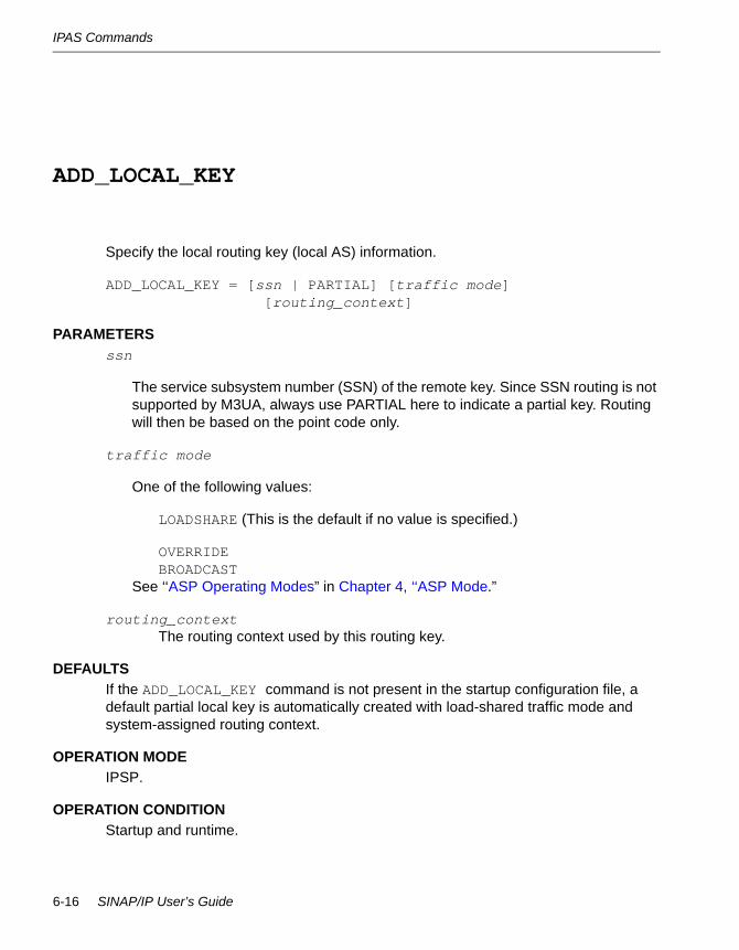
IPAS Commands
ADD_LOCAL_KEY 6-
Specify the local routing key (local AS) information.
ADD_LOCAL_KEY = [ssn | PARTIAL] [traffic mode][routing_context]
PARAMETERSssn
The service subsystem number (SSN) of the remote key. Since SSN routing is not supported by M3UA, always use PARTIAL here to indicate a partial key. Routing will then be based on the point code only.
traffic mode
One of the following values:
LOADSHARE (This is the default if no value is specified.)
OVERRIDEBROADCAST
See ‘‘ASP Operating Modes” in Chapter 4, ‘‘ASP Mode.”
routing_context The routing context used by this routing key.
DEFAULTSIf the ADD_LOCAL_KEY command is not present in the startup configuration file, a default partial local key is automatically created with load-shared traffic mode and system-assigned routing context.
OPERATION MODEIPSP.
OPERATION CONDITIONStartup and runtime.
6-16 SINAP/IP User’s Guide

IPAS Commands
USAGE GUIDELINESThe ADD_LOCAL_KEY command creates a local routing key (local AS) for static registration at startup or runtime. Do not use this command for dynamic registration setup.
Command Reference 6-17

IPAS Commands
ADD_OPC_KEY 6-
Create an OPC-DPC based routing key.
ADD_OPC_KEY = opc traffic mode routing contextlist_of_SG_IDs
PARAMETERSopc
The originating point code of the routing key, in CCITT or ANSI format.
traffic mode One of the following values:
LOADSHAREBROADCASTOVERRIDE_PRIMARYOVERRIDE_BACKUP
See ‘‘ASP Operating Modes” in Chapter 4, ‘‘ASP Mode.”
routing context The numeric value associated with the routing key.
N O T E
The routing context must match with the one configured at the SG.
list of SG IDs A valid SG ID is a numeric value between 0 and 15 (0 <= SG ID <= 15). If the OPC key is serviced by more than one SG, list all the SG IDs here.
DEFAULTSNo default behavior or value.
OPERATION MODEASP.
6-18 SINAP/IP User’s Guide

IPAS Commands
OPERATION CONDITIONStartup.
USAGE GUIDELINESWhen registering m3uagw to the M3UA stack, the DPC is fixed to the SINAP/SS7 PC of the IPAS. The IPAS supports multiple SGs. Each SG can be configured with its own list of Concerned Point Codes. The SG ID specified in an ADD_OPC_KEY command is used to find the CPC list of the SG. The OPC routing key is verified against the CPC list before being stored. A maximum of 128 OPCs can be configured on the IPAS for traffic distribution. With OVERRIDE traffic mode, configure only one primary ASP. You can configure multiple backup ASPs.
Command Reference 6-19
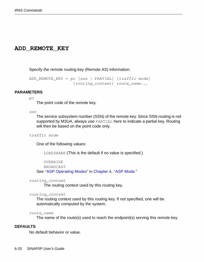
IPAS Commands
ADD_REMOTE_KEY 6-
Specify the remote routing key (Remote AS) information.
ADD_REMOTE_KEY = pc [ssn | PARTIAL] [traffic mode][routing_context] route_name...
PARAMETERSpc
The point code of the remote key.
ssn The service subsystem number (SSN) of the remote key. Since SSN routing is not supported by M3UA, always use PARTIAL here to indicate a partial key. Routing will then be based on the point code only.
traffic mode
One of the following values:
LOADSHARE (This is the default if no value is specified.)
OVERRIDEBROADCAST
See ‘‘ASP Operating Modes” in Chapter 4, ‘‘ASP Mode.”
routing_context The routing context used by this routing key.
routing_context The routing context used by this routing key. If not specified, one will be automatically computed by the system.
route_name The name of the route(s) used to reach the endpoint(s) serving this remote key
DEFAULTSNo default behavior or value.
6-20 SINAP/IP User’s Guide

IPAS Commands
OPERATION MODEIPSP.
OPERATION CONDITIONStartup and runtime.
USAGE GUIDELINESThe ADD_REMOTE_KEY command creates a remote routing key (remote AS) for static registration at startup or runtime. Do not use the command for dynamic registration setup.
Command Reference 6-21

IPAS Commands
ALLOW_TRAFFIC_ON_ROUTE 6-
Allow remote traffic to go through this route.
ALLOW_TRAFFIC_ON_ROUTE = route_name
PARAMETERSroute_name
The symbolic name of the IP route.
DEFAULTSRoutes are created with the allowed state
OPERATION MODEOPERATION MODEASP and IPSP.
OPERATION CONDITIONRuntime.
USAGE GUIDELINESThe ALLOW_TRAFFIC_ON_ROUTE command allows remote traffic to go through a route if the route has previously been prohibited.
Please note that, in the case of IPSP, the route needs to be allowed at both the client and server endpoints for traffic to pass through both ways. Allowing traffic locally only permits the remote traffic to be routed to the local endpoint. The traffic going out will still be prohibited if it is not allowed at the remote endpoint.
6-22 SINAP/IP User’s Guide

IPAS Commands
BIND_UMI_TO_PRIMARY 6-
Bind the user management interface’s listening address to the gateway’s primary address.
BIND_UMI_TO_PRIMARY
PARAMETERSNone.
DEFAULTSBinds to 127.0.0.1.
OPERATION MODEASP and IPSP.
OPERATION CONDITIONStartup.
USAGE GUIDELINESThe BIND_UMI_TO_PRIMARY command binds the user management interface's listening address at the gateway to the gateway's primary address specified in the PRIMARY_LOCAL_HOST command. If the you do not use the BIND_UMI_TO_PRIMARY, the listening address is bound to the default local host address 127.0.0.1.
Command Reference 6-23
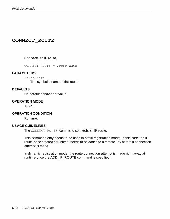
IPAS Commands
CONNECT_ROUTE 6-
Connects an IP route.
CONNECT_ROUTE = route_name
PARAMETERSroute_name
The symbolic name of the route.
DEFAULTSNo default behavior or value.
OPERATION MODEIPSP.
OPERATION CONDITIONRuntime.
USAGE GUIDELINESThe CONNECT_ROUTE command connects an IP route.
This command only needs to be used in static registration mode. In this case, an IP route, once created at runtime, needs to be added to a remote key before a connection attempt is made.
In dynamic registration mode, the route connection attempt is made right away at runtime once the ADD_IP_ROUTE command is specified.
6-24 SINAP/IP User’s Guide
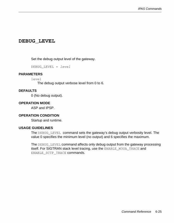
IPAS Commands
DEBUG_LEVEL 6-
Set the debug output level of the gateway.
DEBUG_LEVEL = level
PARAMETERSlevel
The debug output verbose level from 0 to 6.
DEFAULTS0 (No debug output).
OPERATION MODEASP and IPSP.
OPERATION CONDITIONStartup and runtime.
USAGE GUIDELINESThe DEBUG_LEVEL command sets the gateway’s debug output verbosity level. The value 0 specifies the minimum level (no output) and 6 specifies the maximum.
The DEBUG_LEVEL command affects only debug output from the gateway processing itself. For SIGTRAN stack level tracing, use the ENABLE_M3UA_TRACE and ENABLE_SCTP_TRACE commands.
Command Reference 6-25

IPAS Commands
DELETE_IP_CPC 6-
Delete one or more concerned point codes from the SG.
DELETE_IP_CPC = sg_id cpc...
PARAMETERSsg_id
The identification number of the SG. The sg_id is defined by the following command:
M3UA_SG_TO_SGP_DISTRIBUTION_MODE
cpc The concerned point code that needs to be deleted from the SG. You can specify multiple entries separated by spaces.
DEFAULTSNo default behavior or value.
OPERATION MODEASP.
OPERATION CONDITIONRuntime.
USAGE GUIDELINESThe DELETE_IP_CPC command deletes concerned point codes from the SG, so that messages destined for the concerned point code will no longer be routed to this SG.
6-26 SINAP/IP User’s Guide

IPAS Commands
DELETE_IP_ROUTE 6-
Deletes an IP route.
DELETE_IP_ROUTE = route_name
PARAMETERSroute_name
The symbolic name of the route.
DEFAULTSNo default behavior or value
OPERATION MODEASP and IPSP
OPERATION CONDITIONRuntime
USAGE GUIDELINESThe DELETE_IP_ROUTE command deletes an IP route.
The target IP route needs to be prohibited before it can be deleted. In IPSP mode, make sure the IP route is prohibited both ways (at both client and server sides) before issuing this command. See ‘‘USAGE GUIDELINES” for the PROHIBIT_TRAFFIC_ON_ROUTE command.
Command Reference 6-27

IPAS Commands
DELETE_REMOTE_KEY 6-
Delete a remote routing key.
DELETE_REMOTE_KEY = pc [ssn | PARTIAL]
PARAMETERSpc
The point code of the remote key.
ssn
The service subsystem number (SSN) of the remote key. Since SSN routing is not supported by M3UA, always use PARTIAL here for a partial key. Routing will then be based on the point code only.
DEFAULTSNo default behavior or value.
OPERATION MODEIPSP.
OPERATION CONDITIONRuntime.
USAGE GUIDELINESThe DELETE_REMOTE_KEY command deletes an existing remote routing key (remote AS) at runtime.
6-28 SINAP/IP User’s Guide

IPAS Commands
DISABLE_STATISTICS_FOR_NODE 6-
Disable statistics gathering for this node.
DISABLE_STATISTICS_FOR_NODE
PARAMETERSNone.
DEFAULTSStatistics gathering for node is disabled by default.
OPERATION MODEASP and IPSP.
OPERATION CONDITIONRuntime.
USAGE GUIDELINESThe DISABLE_STATISTICS_FOR_NODE command stops traffic-statistics gathering for this gateway node at runtime.
Command Reference 6-29

IPAS Commands
DISABLE_STATISTICS_ON_ROUTES 6-
Disable statistics gathering for all IP routes.
DISABLE_STATISTICS_ON_ROUTES
PARAMETERSNone.
DEFAULTSStatistics gathering for routes is disabled by default.
OPERATION MODEASP and IPSP.
OPERATION CONDITIONRuntime.
USAGE GUIDELINESThe DISABLE_STATISTICS_ON_ROUTES command stops traffic-statistics gathering for all IP routes at runtime.
6-30 SINAP/IP User’s Guide
IPAS Commands
DISPLAY_GATEWAY_VERSION 6-
Display the version of the m3uagw gateway binary.
DISPLAY_GATEWAY_VERSION
PARAMETERSNone.
DEFAULTSNo default behavior or value.
OPERATION MODEASP and IPSP.
OPERATION CONDITIONRuntime.
USAGE GUIDELINESThe DISPLAY_GATEWAY_VERSION command shows the version of the m3uagw gateway binary file at runtime.
Command Reference 6-31
IPAS Commands
DISPLAY_IP_CPCS 6-
Display the concerned point codes served by all configured SGs.
DISPLAY_IP_CPCS
PARAMETERSNone.
DEFAULTSNo default behavior or value.
OPERATION MODEASP.
OPERATION CONDITIONRuntime.
USAGE GUIDELINESThe DISPLAY_IP_CPCS command shows at runtime all the concerned point codes served by all configured SGs that were added by the ADD_IPC_CPC command.
6-32 SINAP/IP User’s Guide

IPAS Commands
DISPLAY_IP_ROUTE 6-
Display the status of an IP route.
DISPLAY_IP_ROUTE = route_name
PARAMETERSroute_name
The symbolic name of an IP route. If ALL is specified, all provisioned IP routes will be displayed.
DEFAULTSNo default behavior or value.
OPERATION MODEASP and IPSP.
OPERATION CONDITIONRuntime.
USAGE GUIDELINESThe DISPLAY_IP_ROUTE command shows the status of a specific IP route at runtime.
Command Reference 6-33
IPAS Commands
DISPLAY_LOCAL_KEY = 6-
Display the ASP local routing key (local AS) status.
DISPLAY_LOCAL_KEY = [opc | dpc]
PARAMETERSopc
The originating point code associated with the local AS.
dpc The destination point code for the local AS.
DEFAULTSNo default behavior or value.
OPERATION MODEASP.
OPERATION CONDITIONRuntime.
USAGE GUIDELINESThe DISPLAY_LOCAL_KEY command shows the status of the local routing key for a DPC or an OPC (local AS) at runtime. The parameter opc is the OPC added at startup by ADD_OPC_KEY. The parameter dpc is the SINAP/SS7 PC of the IPAS if ADD_DPC_KEY is specified at startup.
6-34 SINAP/IP User’s Guide

IPAS Commands
DISPLAY_LOCAL_KEY 6-
Display the IPSP local routing key (local AS) status.
DISPLAY_LOCAL_KEY
PARAMETERSNone.
DEFAULTSNo default behavior or value.
OPERATION MODEIPSP.
OPERATION CONDITIONRuntime.
USAGE GUIDELINESThe DISPLAY_LOCAL_KEY command shows the status of the IPSP single local routing key at runtime.
Command Reference 6-35
IPAS Commands
DISPLAY_LOCAL_KEYS 6-
Display all active local routing keys (local AS) status.
DISPLAY_LOCAL_KEYS
PARAMETERSNone.
DEFAULTSNo default behavior or value.
OPERATION MODEASP.
OPERATION CONDITIONRuntime.
USAGE GUIDELINESThe DISPLAY_LOCAL_KEYS command shows the status of all the active local routing keys (local AS) at runtime.
6-36 SINAP/IP User’s Guide
IPAS Commands
DISPLAY_REMOTE_KEY 6-
Display the status of a specific remote routing key (remote AS).
DISPLAY_REMOTE_KEY = pc [ssn | PARTIAL]
PARAMETERSpc
The point code of the remote key.
ssn The service subsystem number (SSN) of the remote key. Since SSN routing is not supported by M3UA, always use PARTIAL here for partial key.
DEFAULTSNo default behavior or value.
OPERATION MODEIPSP.
OPERATION CONDITIONRuntime.
USAGE GUIDELINESThe DISPLAY_REMOTE_KEY command shows the status of a specific remote routing key (remote AS) at runtime.
Command Reference 6-37

IPAS Commands
DISPLAY_REMOTE_KEYS 6-
Display the status of all remote routing keys (remote AS).
DISPLAY_REMOTE_KEYS
PARAMETERSNone.
DEFAULTSNo default behavior or value.
OPERATION MODEIPSP.
OPERATION CONDITIONRuntime.
USAGE GUIDELINESThe DISPLAY_REMOTE_KEYS command shows the status of all remote routing keys (remote AS) at runtime.
6-38 SINAP/IP User’s Guide
IPAS Commands
DISPLAY_STATISTICS_FOR_NODE 6-
Display traffic statistics gathered for this node.
DISPLAY_STATISTICS_FOR_NODE
PARAMETERSNone.
DEFAULTSStatistics gathering for node is disabled by default.
OPERATION MODEASP and IPSP.
OPERATION CONDITIONRuntime.
USAGE GUIDELINESThe DISPLAY_STATISTICS_FOR_NODE command shows at runtime the traffic statistics gathered for this gateway node since the last time the ENABLE_STATISTICS_FOR_NODE command was issued.
Command Reference 6-39
IPAS Commands
DISPLAY_STATISTICS_FOR_ROUTE 6-
Display traffic statistics gathered for an IP route.
DISPLAY_STATISTICS_FOR_ROUTE = route_name
PARAMETERSroute_name
The symbolic name of an IP route.
DEFAULTSStatistics gathering for route is disabled by default.
OPERATION MODEASP and IPSP.
OPERATION CONDITIONRuntime.
USAGE GUIDELINESThe DISPLAY_STATISTICS_FOR_ROUTE command shows at runtime the traffic statistics gathered for a specific IP route since the last time the ENABLE_STATISTICS_FOR_ROUTE command was issued on it.
6-40 SINAP/IP User’s Guide

IPAS Commands
DISPLAY_SCTP_PARAMETERS 6-
Display the configuration parameters of the SCTP stack.
DISPLAY_SCTP_PARAMETERS
PARAMETERSNone.
DEFAULTSNo default behavior or value.
OPERATION MODEASP and IPSP.
OPERATION CONDITIONRuntime.
USAGE GUIDELINESThe DISPLAY_SCTP_PARAMETERS command shows at runtime the configuration parameters currently used by the underlying SCTP protocol stack.
Command Reference 6-41
IPAS Commands
DYNAMIC_REGISTRATION 6-
Specify that dynamic routing key registration should be used.
DYNAMIC_REGISTRATION
PARAMETERSNone.
DEFAULTSStatic registration is used by default if this is not specified.
OPERATION MODEASP and IPSP.
OPERATION CONDITIONStartup.
USAGE GUIDELINESThe DYNAMIC_REGISTRATION command specifies at startup that dynamic routing key registration should be used.
This means that the local routing key (local AS) information will be sent to the remote SGP or IPSP automatically as part of the connection-setup procedure. The remote SGP or IPSP does not need to configure its corresponding remote key statically.
Specifically for IPSP, when dynamic registration is used, the ADD_REMOTE_KEY command and related remote key operation commands become unnecessary.
6-42 SINAP/IP User’s Guide

IPAS Commands
ENABLE_M3UA_TRACE 6-
Enable the M3UA stack trace output.
ENABLE_M3UA_TRACE
PARAMETERSNone.
DEFAULTSDisabled by default.
OPERATION MODEASP and IPSP.
OPERATION CONDITIONStartup and runtime.
USAGE GUIDELINESThe ENABLE_M3UA_TRACE command turns on trace output of the underlying M3UA protocol stack.
Due to the large volume of tracing outputs generated, enabling trace output introduces some performance overhead. Therefore, do not enable trace output in a production environment.
Command Reference 6-43

IPAS Commands
ENABLE_SCTP_TRACE 6-
Enable the SCTP stack trace output.
ENABLE_M3UA_TRACE
PARAMETERSNone.
DEFAULTSDisabled by default.
OPERATION MODEASP and IPSP.
OPERATION CONDITIONStartup and runtime.
USAGE GUIDELINESThe ENABLE_M3UA_TRACE command turns on trace output of the underlying SCTP protocol stack.
Due to the large volume of tracing outputs generated, enabling trace output introduces some performance overhead. Therefore, do not enable trace output in a production environment.
6-44 SINAP/IP User’s Guide

IPAS Commands
ENABLE_STATISTICS_FOR_NODE 6-
Enable statistics gathering for this node.
ENABLE_STATISTICS_FOR_NODE
PARAMETERSNone.
DEFAULTSStatistics gathering for node is disabled by default.
OPERATION MODEASP and IPSP.
OPERATION CONDITIONRuntime.
USAGE GUIDELINESRun the ENABLE_STATISTICS_FOR_NODE command on a gateway node to start traffic-statistics gathering for that node.
Command Reference 6-45
IPAS Commands
ENABLE_STATISTICS_ON_ROUTES 6-
Enable statistics gathering for all IP routes.
ENABLE_STATISTICS_ON_ROUTES
PARAMETERSNone.
DEFAULTSStatistics gathering for routes is disabled by default.
OPERATION MODEASP and IPSP.
OPERATION CONDITIONRuntime.
USAGE GUIDELINESThe ENABLE_STATISTICS_ON_ROUTES command starts traffic statistics gathering for all IP routes at runtime.
6-46 SINAP/IP User’s Guide

IPAS Commands
GATEWAY_MODE 6-
Specify the operation mode of the gateway.
GATEWAY_MODE = mode
PARAMETERSmode
Can be one of the following mode specifiers:
• IPAS. Application server mode, currently the only supported mode.
• IPSG. Switching gateway mode, not supported.
• IPMT. Message transport mode, not supported.
DEFAULTSNo default behavior or value.
OPERATION MODEASP and IPSP.
OPERATION CONDITIONStartup.
USAGE GUIDELINESThe GATEWAY_MODE command must be present at startup time to specify the operation mode of the gateway process. Currently only IPAS mode is supported. IPAS mode must be used for ASP or IPSP operation.
Command Reference 6-47

IPAS Commands
INITIAL_TRAFFIC_STATE 6-
Specify the operation mode of the gateway.
INITIAL_TRAFFIC_STATE = state
PARAMETERSstate
Can be one of the following state specifiers:
• ALLOWED. Traffic is allowed right after the gateway starts up.
• PROHIBITED. Traffic is prohibited right after gateway starts.
DEFAULTSThe default initial traffic state is ALLOWED.
OPERATION MODEASP and IPSP.
OPERATION CONDITIONStartup.
USAGE GUIDELINESThe INITIAL_TRAFFIC_STATE command specifies the initial traffic state of the gateway process after it starts up. If this command is not present, the default traffic state is allowed, and the remote side can start sending traffic to this node as soon as the endpoint is active.
6-48 SINAP/IP User’s Guide
IPAS Commands
IS_SERVER 6-
Specify the gateway is acting as IPSP server.
IS_SERVER
PARAMETERSNone.
DEFAULTSIf not specified, the gateway acts as the IPSP client.
OPERATION MODEIPSP.
OPERATION CONDITIONStartup.
USAGE GUIDELINESThe IS_SERVER command specifies that the gateway is acting as an IPSP server. If the command is not run, the gateway is acting as an IPSP client.
An IPSP server can only communicate with an IPSP client and vice versa.
The connection is always initiated from client to server. Generally the server process should be started before the client process.
Command Reference 6-49

IPAS Commands
LOCAL_SCTP_PORT 6-
Sets the local SCTP port number.
LOCAL_SCTP_PORT = sctp_port
PARAMETERSsctp_port
The port number of the local SCTP stack.
DEFAULTSThe default port number is 8888.
OPERATION MODEASP and IPSP.
OPERATION CONDITIONStartup.
USAGE GUIDELINESThe LOCAL_SCTP_PORT command sets the local SCTP port number used to send and receive traffic.
N O T E
SCTP port 2905 is the well-known port for M3UA
6-50 SINAP/IP User’s Guide

IPAS Commands
M3UA_AUDIT_TIMER 6-
Set the DAUD timer value of the M3UA stack.
M3UA_AUDIT_TIMER = timeout_secs
PARAMETERStimeout_secs
The DAUD timer value in seconds.
DEFAULTS5 seconds.
OPERATION MODEASP and IPSP.
OPERATION CONDITIONStartup.
USAGE GUIDELINESThe M3UA_AUDIT_TIMER command sets the value of the M3UA stack’s DAUD timer in seconds.
Command Reference 6-51
IPAS Commands
M3UA_CONGESTION_TIMER 6-
Set the congestion timer value of the M3UA stack.
M3UA_CONGESTION_TIMER = timeout_secs
PARAMETERStimeout_secs
The congestion timer value in seconds.
DEFAULTS2 seconds
OPERATION MODEASP and IPSP.
OPERATION CONDITIONStartup.
USAGE GUIDELINESThe M3UA_CONGESTION_TIMER command sets the value of the M3UA stack’s congestion timer in seconds.
6-52 SINAP/IP User’s Guide

IPAS Commands
M3UA_MAX_RETRANSMISSIONS 6-
Set the number of maximum retransmission attempts of the M3UA stack.
M3UA_MAX_RETRANSMISSIONS = count
PARAMETERScount
The count of the maximum number of retransmission attempts.
DEFAULTS1.
OPERATION MODEASP and IPSP.
OPERATION CONDITIONStartup.
USAGE GUIDELINESThe M3UA_MAX_RETRANSMISSIONS command sets the value of the M3UA stack’s maximum number of retransmission attempts.
Command Reference 6-53

IPAS Commands
M3UA_RETRANSMISSION_TIME 6-
Set the retransmission timer values of the M3UA stack.
M3UA will use following values to retransmit ASPUP, ASPDN, ASPAC, ASPIA.
If retransmit counter is <= M3UA_SWITCHOVER_COUNT, M3UA_ASPM_RETRAN_TIME_LOW is waited before retransmit the protocol message.
If retransmit counter is > M3UA_SWITCHOVER_COUNT, M3UA_ASPM_RETRAN_TIME_HIGH is waited before retransmit the protocol message.
If retransmit counter is >= M3UA_MAX_RETRANSMISSIONS, the retransmit is over.
M3UA_RETRANSMISSION_TIME = low_sec high_sec
PARAMETERSlow_sec
The initial low time of the retransmission timer value in seconds.
high_sec The switch over high time of the retransmission timer value in seconds.
DEFAULTSlow_sec: 1 second.
high_sec: 2 seconds.
OPERATION MODEASP and IPSP.
OPERATION CONDITIONStartup.
USAGE GUIDELINESThe M3UA_RETRANSMISSION_TIME command sets the value of the M3UA stack’s retransmission timer in seconds.
6-54 SINAP/IP User’s Guide
IPAS Commands
M3UA_SG_TO_SGP_DISTRIBUTION_MODE 6-
Define an SG and set the traffic distribution mode for remote SGPs in an remote SG.
M3UA_SG_TO_SGP_DISTRIBUTION_MODE = sg_id traffic_mode
PARAMETERSsg_id
The numeric identifier of an SG. The valid range for sg_id is 0 - 15.
traffic_mode Can be one of the following traffic-mode specifiers:
• OVERRIDE. Use the override traffic mode. Traffic is routed to one single active SGP only. The standby SGP will become active on an override basis.
• LOADSHARE. Use the load-shared traffic mode. Traffic is routed to SGPs in a round-robin fashion.
• BROADCAST. Use the broadcast traffic mode. All traffic is broadcast to all SGPs.
DEFAULTSNo default behavior or value.
OPERATION MODEASP.
OPERATION CONDITIONStartup.
USAGE GUIDELINESThe M3UA_SG_TO_SGP_DISTRIBUTION_MODE command sets the distribution mode of traffic among remote SGPs within an remote SG. The traffic mode will only make difference if there is more than one SGP in the SG.
For the IPAS, this command also serves the purpose of declaring an instance of remote SG and assigning an SG ID to it. The SG ID can then be used in other places that require it, such as the ADD_IP_ROUTE or ADD_IP_CPC commands.
Command Reference 6-55

IPAS Commands
M3UA_SWITCHOVER_COUNT 6-
Set the M3UA switch-over count.
M3UA_SWITCHOVER_COUNT = count
PARAMETERScount
The switch-over count.
DEFAULTS1.
OPERATION MODEASP and IPSP.
OPERATION CONDITIONStartup and runtime.
USAGE GUIDELINESThe M3UA_SWITCHOVER_COUNT command sets the value of the switch-over count of the retransmit timer for the M3UA stack.
6-56 SINAP/IP User’s Guide

IPAS Commands
OUTPUT_FILE 6-
Set the log output file name and path.
OUTPUT_FILE = file
PARAMETERSfile
The full UNIX name and path of the output file.
DEFAULTSIf not specified, output is directed to standard output (stdout).
OPERATION MODEASP and IPSP.
OPERATION CONDITIONStartup.
USAGE GUIDELINESThe OUTPUT_FILE command sets the output file and path for error, debug and log printouts at startup. If an output file needs to be specified, this command has to appear first in the startup configuration file.
Command Reference 6-57
IPAS Commands
PRIMARY_LOCAL_HOST 6-
Specify the primary local host for the stack.
PRIMARY_LOCAL_HOST = host
PARAMETERShost
The local host name or IP address
DEFAULTSNo default behavior or value.
OPERATION MODEASP and IPSP.
OPERATION CONDITIONStartup.
USAGE GUIDELINESThis command sets the local host name or IP address used to send and receive traffic.
6-58 SINAP/IP User’s Guide
IPAS Commands
PROHIBIT_TRAFFIC_ON_ROUTE 6-
Prohibit remote traffic to go through this route.
PROHIBIT_TRAFFIC_ON_ROUTE = route_name
PARAMETERSroute_name
The symbolic name of the IP route.
DEFAULTSRoutes are created with allowed state.
OPERATION MODEASP and IPSP.
OPERATION CONDITIONRuntime.
USAGE GUIDELINESThe PROHIBIT_TRAFFIC_ON_ROUTE command prohibits remote traffic from going through this route if it is currently allowed.
Please note that, in the case of IPSP, the route needs to be prohibited at both the client and server endpoints to stop traffic both ways. Prohibiting traffic locally only stops the remote traffic from being routed to the local endpoint. The traffic going out will still be allowed if it is not prohibited at the remote endpoint.
Command Reference 6-59

IPAS Commands
RECONNECT_TIMER 6-
Sets the timer value for the IPAS’s attempts to reconnect.
RECONNECT_TIMER = timeout_secs
PARAMETERStimeout_secs
The timeout value in seconds.
DEFAULTS5 seconds.
OPERATION MODEASP and IPSP.
OPERATION CONDITIONStartup and runtime.
USAGE GUIDELINESThe RECONNECT_TIMER command sets the periodic interval between attempts by the IPAS to re-establish a previously disconnected route.
N O T E
When a route is first disrupted, the SCTP retries over all valid paths and tries to tolerate the fault, if possible. The reconnect here only happens after the SCTP has finished retrying and declared that the connection is lost. Tuning the SCTP layer timeout parameter affects how soon a route is considered disconnected.
6-60 SINAP/IP User’s Guide

IPAS Commands
SCTP_ASSOC_MAX_RETRANS 6-
Set the maximum number of association retransmission attempts for the SCTP stack.
SCTP_ASSOC_MAX_RETRANS = count
PARAMETERScount
The count of the maximum association retransmission attempts.
DEFAULTS3 if only a single connection per association is used.
8 if double connections per association (multi-home) are used.
OPERATION MODEASP and IPSP.
OPERATION CONDITIONStartup and runtime.
USAGE GUIDELINESThe SCTP_ASSOC_MAX_RETRANS command sets the value of the maximum number of retransmission attempts on an association for the SCTP stack.
The value of count must be greater than the value set with the SCTP_PATH_MAX_RETRANS command (see ‘‘USAGE GUIDELINES” for the SCTP_PATH_MAX_RETRANS command). For additional information, see RFC2960, Section 8.
The appropriate value for count is network dependent. Setting it too low could lead to premature congestion notifications (alarms indicating SCTP congestion) and result in disconnection. Generally, count should be set higher when multi-home setup is used, to allow more tries over different paths of the same association.
As this value requires careful tuning of a network for proper performance, the default setting is recommended if the network characteristics are unknown.
Command Reference 6-61

IPAS Commands
SCTP_BUNDLING_TIME 6-
Set the bundling time for the SCTP stack.
SCTP_BUNDLING_TIME = time_ms
PARAMETERStime_ms
The SCTP bundling time in milliseconds.
DEFAULTS100 milliseconds.
OPERATION MODEASP and IPSP.
OPERATION CONDITIONStartup and runtime.
USAGE GUIDELINESThe SCTP_BUNDLING_TIME command sets the value of the bundling time for the SCTP stack. It is the time interval after which the SCTP buffer is flushed (if not full).
6-62 SINAP/IP User’s Guide

IPAS Commands
SCTP_FRAGMENTATION_ALLOWED 6-
Specifies whether to allow fragmentation of SCTP messages.
SCTP_FRAGMENTATION_ALLOWED = allowed
PARAMETERSallowed
One of the following values:
• TRUE. Allows SCTP message fragmentation.
• FALSE. Disallows SCTP message fragmentation. An error will be generated by the stack if a message cannot be transmitted without fragmentation.
DEFAULTSFALSE.
OPERATION MODEASP and IPSP.
OPERATION CONDITIONStartup and runtime.
USAGE GUIDELINESThe SCTP_FRAGMENTATION_ALLOWED command selects the message fragmentation option of the SCTP stack. Fragmentation generally introduces extra processing overhead.
Command Reference 6-63

IPAS Commands
SCTP_HEARTBEAT 6-
Set the heartbeat interval for the SCTP stack.
SCTP_HEARTBEAT = time_sec
PARAMETERStime_sec
The SCTP heartbeat interval in seconds.
DEFAULTS3 seconds.
OPERATION MODEASP and IPSP.
OPERATION CONDITIONStartup and runtime.
USAGE GUIDELINESThe SCTP_HEARTBEAT command sets the heartbeat interval for the SCTP stack.
The appropriate value for time_sec is network dependent. Setting it too low could result in unnecessary network traffic. Setting it too high could result in taking longer to detect connection loss when no payload traffic is running.
As this value requires careful tuning of a network for proper performance, the default setting is recommended if the network characteristics are unknown.
6-64 SINAP/IP User’s Guide

IPAS Commands
SCTP_HIGH_CONG_LEVEL 6-
Set the high congestion level for the SCTP stack.
SCTP_HIGH_CONG_LEVEL = value
PARAMETERSvalue
The SCTP high congestion level percentage.
DEFAULTS80 percent.
OPERATION MODEASP and IPSP
OPERATION CONDITIONStartup and runtime
USAGE GUIDELINESThe SCTP_HIGH_CONG_LEVEL command sets the high congestion level for the SCTP stack. If the percentage level of SCTP buffer occupancy exceeds value, high congestion is reported.
The appropriate setting for value is network dependent. As this value requires careful tuning of a network for proper performance, the default setting is recommended if the network characteristics are unknown.
Command Reference 6-65
IPAS Commands
SCTP_LOW_CONG_LEVEL 6-
Set the low congestion level for the SCTP stack.
SCTP_LOW_CONG_LEVEL = value
PARAMETERSvalue
The SCTP low congestion level percentage.
DEFAULTS60 percent.
OPERATION MODEASP and IPSP.
OPERATION CONDITIONStartup and runtime.
USAGE GUIDELINESThe SCTP_LOW_CONG_LEVEL command sets the low congestion level for the SCTP stack. If the percentage level of SCTP buffer occupancy exceeds value, but is less than the value set by the SCTP_HIGH_CONG_LEVEL command (see ‘‘USAGE GUIDELINES” for the SCTP_HIGH_CONG_LEVEL command), low congestion is reported.
The appropriate setting for value is network dependent. As this value requires careful tuning of a network for proper performance, the default setting is recommended if the network characteristics are unknown.
6-66 SINAP/IP User’s Guide

IPAS Commands
SCTP_MAX_ENDPOINTS 6-
Set the SCTP maximum number of endpoints.
SCTP_MAX_ENDPOINTS = value
PARAMETERSvalue
The maximum number of SCTP endpoints.
DEFAULTS10.
OPERATION MODEASP and IPSP
OPERATION CONDITIONStartup
USAGE GUIDELINESThe SCTP_MAX_ENDPOINTS command sets the maximum number of SCTP endpoints. Valid settings for value are in the range 0 to 200.
Command Reference 6-67

IPAS Commands
SCTP_MAX_RX_BUFFERS 6-
Set the maximum number of SCTP receive buffers.
SCTP_MAX_RX_BUFFER = value
PARAMETERSvalue
The maximum number of receive buffers for the SCTP stack. Valid settings are in the range 1 to 65535.
DEFAULTS100.
OPERATION MODEASP and IPSP.
OPERATION CONDITIONStartup.
USAGE GUIDELINESThe SCTP_MAX_RX_BUFFER command sets the maximum number of buffers that SCTP can use in reception.
This parameter should be tuned if premature congestion indications arise during traffic.
6-68 SINAP/IP User’s Guide
IPAS Commands
SCTP_MAX_TX_BUFFERS 6-
Set the maximum number of SCTP receive buffers.
SCTP_MAX_TX_BUFFER = value
PARAMETERSvalue
The maximum number of send buffers for the SCTP stack. Valid settings are in the range 1 to 65535.
DEFAULTS100.
OPERATION MODEASP and IPSP.
OPERATION CONDITIONStartup.
USAGE GUIDELINESThe SCTP_MAX_TX_BUFFER command sets the maximum number of buffers that SCTP can use in transmission.
This parameter should be tuned if premature congestion indications arise during traffic.
Command Reference 6-69
IPAS Commands
SCTP_NO_CONG_LEVEL 6-
Set the no congestion level of the SCTP stack.
SCTP_NO_CONG_LEVEL = value
PARAMETERSvalue
The SCTP no congestion level percentage.
DEFAULTS40 percent.
OPERATION MODEASP and IPSP
OPERATION CONDITIONStartup and runtime.
USAGE GUIDELINESThe SCTP_NO_CONG_LEVEL command sets the no congestion level for the SCTP stack. If the percentage level of SCTP buffer occupancy falls below value, no congestion is reported.
The appropriate setting for value is network dependent. As this value requires careful tuning of a network for proper performance, the default setting is recommended if the network characteristics are unknown.
6-70 SINAP/IP User’s Guide

IPAS Commands
SCTP_PATH_MAX_RETRANS 6-
Set the number of maximum path retransmission attempts for the SCTP stack.
SCTP_PATH_MAX_RETRANS = count
PARAMETERScount
The count of the maximum path retransmission attempts.
DEFAULTS2.
OPERATION MODEASP and IPSP.
OPERATION CONDITIONStartup and runtime.
USAGE GUIDELINESThe SCTP_PATH_MAX_RETRANS command sets the value of the SCTP stack’s number of maximum retransmission attempts on each path of the association. Note that each association will contain more than one path only if multi-home setup is used.
The value of count must be smaller than the value set with the SCTP_ASSOC_MAX_RETRANS command (see ‘‘USAGE GUIDELINES” for the SCTP_ASSOC_MAX_RETRANS command). For additional information, see RFC2960, Section 8.
The appropriate value for count is network dependent. Setting it too low could lead to premature congestion notifications (alarms indicating SCTP congestion) and result in disconnection.
As this value requires careful tuning of a network for proper performance, the default setting is recommended if the network characteristics are unknown.
Command Reference 6-71
IPAS Commands
SCTP_RTO_ALPHA 6-
Set the retransmission timeout Alpha percentage for the SCTP stack.
SCTP_RTO_ALPHA = value
PARAMETERSvalue
The value of the retransmission timeout Alpha percentage.
DEFAULTS12 percent.
OPERATION MODEASP and IPSP.
OPERATION CONDITIONStartup and runtime.
USAGE GUIDELINESThe SCTP_RTO_ALPHA command sets the value of the retransmission timeout (RTO) Alpha percentage for the SCTP stack. This must be smaller than the value set with the SCTP_RTO_BETA command (see ‘‘USAGE GUIDELINES” for the SCTP_RTO_BETA command). For additional information, see RFC2960, Section 6.3.1.
The appropriate value for count is network dependent.
As this value requires careful tuning of a network for proper performance, the default setting is recommended if the network characteristics are unknown.
6-72 SINAP/IP User’s Guide
IPAS Commands
SCTP_RTO_BETA 6-
Set the retransmission timeout Beta percentage for the SCTP stack.
SCTP_RTO_BETA = value
PARAMETERSvalue
The value of the retransmission timeout Beta percentage.
DEFAULTS25 percent.
OPERATION MODEASP and IPSP.
OPERATION CONDITIONStartup and runtime.
USAGE GUIDELINESThe SCTP_RTO_BETA command sets the value of the retransmission timeout (RTO) Beta percentage for the SCTP stack. This must be larger than the value set with the SCTP_RTO_ALPHA command (see ‘‘USAGE GUIDELINES” for the SCTP_RTO_ALPHA command). For additional information, see RFC2960, Section 6.3.1.
The appropriate value for count is network dependent.
As this value requires careful tuning of a network for proper performance, the default setting is recommended if the network characteristics are unknown.
Command Reference 6-73

IPAS Commands
SCTP_RTO_INIT 6-
Set the initial value of the retransmission timeout for the SCTP stack.
SCTP_RTO_INIT = time_ms
PARAMETERStime_ms
The initial retransmission timeout in milliseconds.
DEFAULTS3000.
OPERATION MODEASP and IPSP.
OPERATION CONDITIONStartup and runtime.
USAGE GUIDELINESThe SCTP_RTO_INIT command sets the value of the initial retransmission timeout (RTO) for the SCTP stack in milliseconds.
The value of time_ms must be greater than the value set with the SCTP_RTO_MIN command (see USAGE GUIDELINES for the SCTP_RTO_MIN command). For additional information, see RFC2960, Section 6.3.1.
The appropriate value for count is network dependent.
As this value requires careful tuning of a network for proper performance, the default setting is recommended if the network characteristics are unknown.
6-74 SINAP/IP User’s Guide

IPAS Commands
SCTP_RTO_MAX 6-
Set the maximum value of the retransmission timeout for the SCTP stack.
SCTP_RTO_MAX = time_ms
PARAMETERStime_ms
The maximum retransmission timeout in milliseconds.
DEFAULTS60000.
OPERATION MODEASP and IPSP.
OPERATION CONDITIONStartup and runtime.
USAGE GUIDELINESThe SCTP_RTO_MAX command sets the value of the maximum retransmission timeout (RTO) for the SCTP stack in milliseconds. RTOs above this level are truncated to this level.
The value of time_ms must be greater than the value set with the SCTP_RTO_INIT and SCTP_RTO_MIN commands (see ‘‘USAGE GUIDELINES” for the SCTP_RTO_INIT and ‘‘USAGE GUIDELINES” for the SCTP_RTO_MIN command). For additional information, see RFC2960, Section 6.3.1.
The appropriate value for count is network dependent.
As this value requires careful tuning of a network for proper performance, the default setting is recommended if the network characteristics are unknown.
Command Reference 6-75

IPAS Commands
SCTP_RTO_MIN 6-
Set the minimum value of the retransmission timeout for the SCTP stack.
SCTP_RTO_MIN = time_ms
PARAMETERStime_ms
The minimum retransmission timeout in milliseconds.
DEFAULTS1000.
OPERATION MODEASP and IPSP.
OPERATION CONDITIONStartup and runtime.
USAGE GUIDELINESThe SCTP_RTO_MIN command sets the value of the minimum retransmission timeout (RTO) for the SCTP stack in milliseconds. All RTOs less than this are rounded up to this level.
The value of time_ms must be less than the value set with the SCTP_RTO_INIT command (see ‘‘USAGE GUIDELINES” for the SCTP_RTO_INIT command). For additional information, see RFC2960, Section 6.3.1.
The appropriate value for count is network dependent.
As this value requires careful tuning of a network for proper performance, the default setting is recommended if the network characteristics are unknown.
6-76 SINAP/IP User’s Guide
IPAS Commands
SECONDARY_LOCAL_HOST 6-
Specify the secondary local host for the stack.
SECONDARY_LOCAL_HOST = host
PARAMETERShost
The secondary local host name or IP address
DEFAULTSNo default behavior or value.
OPERATION MODEASP and IPSP.
OPERATION CONDITIONStartup.
USAGE GUIDELINESThe SECONDARY_LOCAL_HOST command sets the secondary local host name or IP address used to send and receive traffic.
Use this command to set up SCTP multi-home. After using this command, you must use the ADD_IP_ROUTE command to complete the setup by specifying the corresponding secondary remote host or IP address (see ‘‘USAGE GUIDELINES“ for the ADD_IP_ROUTE command).
Command Reference 6-77

IPAS Commands
SHUTDOWN 6-
Initiate a graceful shutdown sequence.
SHUTDOWN
PARAMETERSNone.
DEFAULTSNo default behavior or value.
OPERATION MODEASP and IPSP.
OPERATION CONDITIONRuntime.
USAGE GUIDELINESThe SHUTDOWN command initiates a graceful shutdown sequence for the m3uagw process.
You can also trigger graceful shutdown by pressing CTRL+C, if the m3uagw process is running in the foreground.
6-78 SINAP/IP User’s Guide

IPAS Commands
SINAP_APPLICATION_NAME 6-
Specify the SINAP/SS7 application name of the m3uagw process
SINAP_APPLICATION_NAME = name
PARAMETERSname
The SINAP/SS7 application name
DEFAULTSM3GW.
OPERATION MODEASP and IPSP.
OPERATION CONDITIONStartup.
USAGE GUIDELINESThe SINAP_APPLICATION_NAME command sets the SINAP/SS7 application name of the m3uagw process at startup time.
Only the first three letters are used to form the application name. The fourth letter is always set to “G”. For example, suppose that you give the following command:
SINAP_APPLICATION_NAME = M3UAGW
In this case, the SINAP/SS7 application name will be set to M3UG.
It is not normally necessary to set the SINAP/SS7 application name, unless the default name M3GW conflicts with the name of another SINAP/SS7 application running on the same SINAP/SS7 node.
Command Reference 6-79

IPAS Commands
SINAP_QUEUE_SIZE 6-
Specify the SINAP SS7 message queue size
SINAP_QUEUE_SIZE = value
PARAMETERSvalue
The SINAP SS7 message queue size. Valid settings are in the range 1 to 30000.
DEFAULTS256.
OPERATION MODEASP and IPSP.
OPERATION CONDITIONStartup.
USAGE GUIDELINESThe SINAP_QUEUE_SIZE command sets the SINAP/SS7 queue size for incoming and outgoing SS7 messages to and from the SINAP/SS7 application.
When you specify the queue size, the values of SINAP/SS7 max_msu_input_queue, max_msu_output_queue, and max_msu_holding_queue for the m3uagw process are set to this value. This value requires tuning to achieve optimal performance.
6-80 SINAP/IP User’s Guide
IPAS Commands
UMI_PORT 6-
Change the listening port for the user management interface.
UMI_PORT = value
PARAMETERSvalue
The port number of the listening port for the user management interface.
DEFAULTS8655.
OPERATION MODEASP and IPSP.
OPERATION CONDITIONStartup.
USAGE GUIDELINESThe UMI_PORT command changes the listening port at the gateway for the user management interface to value. If this command is not specified, the default listening port 8655 is used.
Command Reference 6-81

IPAS Commands
6-82 SINAP/IP User’s Guide

Chapter 7Glossary7-
• Application Server (AS)
• A logical application that provides a service.
• Application Server Process (ASP)
• A process instance of an AS.
• Active, backup, loadsharing, or broadcast process of an AS.
• ASP may be part of one or more AS’s.
• Association
• AN SCTP association (connection) between peer ASPs.
• Client/Server
• One of the ASPs is a client and one is a server.
• Client initiates the association.
• Concerned Point Code (CPC)
• Destination Point Code (DPC)
• Failover
• Uses model “n+k”, where “n” ASPs are required to support the traffic load, and “k” ASPs are available to takeover from failed ASP.
• Internet Protocol Signaling Point (IPSP)
• A process instance of an IP-based application. An IPSP is essentially the same as an ASP.
• Local Routing Context (LRC)
• An implementation dependent value to augment the RK.
• Originating Point Code (OPC)
• Routing Context (RC)
• A value that uniquely identifies an RK.
• Defined dynamically or statically.
• Routing Key (RK)
Glossary 7-1
Glossary
• A set of SS7 parameters and parameter values used to define traffic for a specific ASP.
• Signaling Gateway (SG)
• Appears to the SS7 network as an SS7 signaling point.
• Transports MTP3 User messages over the M3UA/SCTP/IP protocols.
• Signaling Gateway Process (SGP)
• A process instance of a Signaling Gateway.
• SS7 Signaling Endpoint (SEP)
7-2 SINAP/IP User’s Guide
Appendix AA-SINAP/IP Reliability
This appendix provides a brief description of multi-homing, which is one of the prime advantages of using SCTP (TCP does not offer multi-homing), and of the Stratus ft Linux virtual network device (VND), which supports Ethernet port redundancy with failover.
Reliability of SS7 over IP can be achieved by using a combination of VND from Stratus and standard SCTP multi-homing. The Stratus ftServer hardware fault tolerant VND deals with hardware failures without disrupting service by switching traffic from a primary port to a secondary port. Multi-homing deals with IP transport failures by switching traffic from a primary IP address to a secondary IP address.
Virtual Network Device (VND)Stratus ft Linux systems provide the virtual network device (VND) driver, which supports Ethernet port redundancy with failover. This section only applies to ftServer T Series systems running the ft Linux operating system.
Use the lspci command to determine an adapter’s PCI bus, slot, and function number.
For example:
01:01.0 Ethernet controller: Intel Corp. 82546EB Gigabit Ethernet Controller (Copper) (rev01)
This device is named gb01.01.0
For configuration details, see the Stratus ft Linux System Administrator’s Guide (R003L) for information about configuring Ethernet devices.
VND presents a group of physical interfaces, a VND group, as a single virtual network interface (for example ha0) to the kernel. This virtual interface is managed exactly as if it were a physical Linux network interface (for example via /etc/sysconfig/network-scripts/ifcfg-ha0).
SINAP/IP Reliability A-1
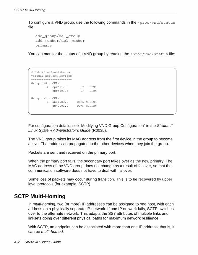
SCTP Multi-Homing
To configure a VND group, use the following commands in the /proc/vnd/status file:
add_group/del_groupadd_member/del_memberprimary
You can monitor the status of a VND group by reading the /proc/vnd/status file:
For configuration details, see “Modifying VND Group Configuration” in the Stratus ft Linux System Administrator’s Guide (R003L).
The VND group takes its MAC address from the first device in the group to become active. That address is propagated to the other devices when they join the group.
Packets are sent and received on the primary port.
When the primary port fails, the secondary port takes over as the new primary. The MAC address of the VND group does not change as a result of failover, so that the communication software does not have to deal with failover.
Some loss of packets may occur during transition. This is to be recovered by upper level protocols (for example, SCTP).
SCTP Multi-HomingIn multi-homing, two (or more) IP addresses can be assigned to one host, with each address on a physically separate IP network. If one IP network fails, SCTP switches over to the alternate network. This adapts the SS7 attributes of multiple links and linksets going over different physical paths for maximum network resilience.
With SCTP, an endpoint can be associated with more than one IP address; that is, it can be multi-homed.
# cat /proc/vnd/statusVirtual Network Devices-----------------------Group ha0 : OKAY
-> epro01.06 UP LINKepro40.06 UP LINK
Group ha1 : OKAY-> gb01.03.0 DOWN NOLINK
gb40.03.0 DOWN NOLINK
A-2 SINAP/IP User’s Guide

SCTP Multi-Homing
Likewise, the destination from the endpoint can also be multi-homed; that is, it can have two separate IP addresses.
The IPAS has the capability to support up to two local addresses (by means of the PRIMARY_LOCAL_HOST and SECONDARY_LOCAL_HOST commands) and two remote addresses per Signaling Gateway Process (SGP) by means of the ADD_IP_ROUTE command. There is one ADD_IP_ROUTE command per SGP. (See Chapter 6, ‘‘Command Reference,” for complete information on the commands discussed in this chapter.)
Packets are sent and received on the primary path. Paths connect primary and secondary IP addresses. If a path fails, the alternative path is used to retransmit data. Acknowledgements for DATA or heart-beat chunks are used to determine path failure. IP failures result in switchover from a primary IP address to a secondary IP address. Figure A-1 illustrates SCTP multi-home failover.
Figure A-1. SCTP Multi-Home Failover
SCTP End Point SCTP End Point
SCTP AssociationPort
NumberPort
Number
Primary IP Address
Secondary IP Address
Primary IP Address
Secondary IP Address
SCTP User Application
SCTP User Application
SCTP Transport Service
SCTP Transport Service
IP Network Service
IP Network Service
•Packets are sent/received on primary path.•Paths connect primary and secondary IP addresses.•In case of path failure, alternative path are used to retransmit data. •Acknowledgement for DATA or heart-beat chunks are used to determine path failure.
SINAP/IP Reliability A-3

SCTP Multi-Homing
The following commands configure m3uagw to use SCTP multi-home:
The following SCTP parameters affect multi-home fail-over:
• SCTP_HEARTBEAT. The interval between the heartbeat chunks.
• SCTP_PATH_MAX_RETRANS. The number of maximum retransmission attempts on each path of the association. If no ack is received for the SCTP packets (data or heartbeat chunks), the path is marked inactive.
• SCTP_ASSOC_MAX_RETRANS. The number of maximum retransmission attempts on the associations. If no acknowledgement is received, the association is closed.
Figure A-2. SCTP Multi-Home Failover Sample Configuration
PRIMARY_LOCAL_HOST = <SCTP primary addr SECONDARY_LOCAL_HOST = <SCTP secondary addr ADD_IP_ROUTE = <SG ID <dest primary addr <dest secondary addr <sctp port <route name
SGSINAPSINAPIPASIPAS
ftServer
SGPASP
IP
192.168.1.100
192.168.2.100
192.168.2.50
192.168.1.50
A-4 SINAP/IP User’s Guide

SCTP Multi-Home Failover Sample - IPAS Setup
SCTP Multi-Home Failover Sample - IPAS SetupFigure A-2 shows an example of setting up the IPAS for SCTP multi-home failover. The following steps are used to set up this configuration:
1. Specify primary and secondary local IP addresses:
PRIMARY_LOCAL_HOST = 192.168.1.100SECONDARY_LOCAL_HOST = 192.168.2.100
2. Specify primary and secondary remote IP addresses in IP route:
ADD_IP_ROUTE = 1 192.168.1.50 192.168.2.50 2905 route13. Set up timeout for faster failover time to avoid congestion:
SCTP_PATH_MAX_RETRANS = 4SCTP_ASSOC_MAX_RETRANS = 10SCTP_HEARTBEAT = 30SCTP_RTO_INIT = 1000SCTP_RTO_MAX = 2000SCTP_RTO_MIN = 1000
Operational ConfigurationsThis section describes the basic SS7-over-IP network configurations in which the IPAS can be used. Four basic configurations are possible:
• Non-multi-homed IPAS.
• Multi-homed IPAS.
• Multi-SGP Equipped IPAS.
• Multi-Route Equipped Apposes.
Non-Multi-Homed IPASThis is the same as that described in Chapter 4, ‘‘ASP Mode,” and Chapter 5, ‘‘IPSP Mode.” It suffers from at least three potential points of failure including: IP network failure, system failure and application failure. However, ASP endpoints tend to be replicated and distributed.
Multi-Homed IPASIn this configuration the two IP connections are on separate IP networks. Thus there is no single point of failure at the network level. This is comparable to the traditional way SINAP/SS7 is operated, where two IP connections logically represent links/linksets in which the route will not fail if at least one of these is operational.
Figure A-3 illustrates this configuration.
SINAP/IP Reliability A-5
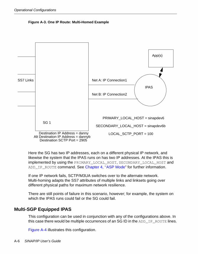
Operational Configurations
Figure A-3. One IP Route: Multi-Homed Example
Here the SG has two IP addresses, each on a different physical IP network, and likewise the system that the IPAS runs on has two IP addresses. At the IPAS this is implemented by using the PRIMARY_LOCAL_HOST, SECONDARY_LOCAL_HOST and ADD_IP_ROUTE command. See Chapter 4, ‘‘ASP Mode” for further information.
If one IP network fails, SCTP/M3UA switches over to the alternate network. Multi-homing adapts the SS7 attributes of multiple links and linksets going over different physical paths for maximum network resilience.
There are still points of failure in this scenario, however; for example, the system on which the IPAS runs could fail or the SG could fail.
Multi-SGP Equipped IPASThis configuration can be used in conjunction with any of the configurations above. In this case there would be multiple occurrences of an SG ID in the ADD_IP_ROUTE lines.
Figure A-4 illustrates this configuration.
SG 1
SS7 Links
IPAS
Net A: IP Connection1
Net B: IP Connection2
Destination IP Address = dannyAlt Destination IP Address = dannyb
Destination SCTP Port = 2905
App(s)
PRIMARY_LOCAL_HOST = sinapdev6
SECONDARY_LOCAL_HOST = sinapdev6b
LOCAL_SCTP_PORT = 100
A-6 SINAP/IP User’s Guide

Operational Configurations
Figure A-4. IPAS to Multiple SGPs in One SG Example
In this example there are two IP routes leading to two SGPs within SG1. The SG ID (see Chapter 4, ‘‘ASP Mode”) is set at 1 to denote SG1. If the SG1 loadshares incoming traffic between its two SGPs, the M3UA_SG_TO_SGP_DISTRIBUTION_MODE for SG1 would be set to LOADSHARE.
Multi-Route Equipped IPASesIn this configuration, a single IP connection connects each IPAS and its applications (up to 16) to the SGs. Each IP connection is interspersed among different IP networks (to avoid a single point of failure on a solitary network disrupting traffic for all).
Figure A-5 illustrates this configuration.
SG1
SGP1
SGP2
SS7 Links
IPAS
SG1, IP_ROUTE 0
SG1, IP_ROUTE 1
M3UA_SG_TO_SGP_DISTRIBUTION_MODE 1LOADSHARE
SINAP/IP Reliability A-7

Operational Configurations
Figure A-5. Multiple SGs and IPASes example
Here two systems use the same SS7 point code, and the application is duplicated.
This configuration allows a degree of fault tolerance for the IPASes and applications. The default mode would be loadshare and traffic loadshared between the IPASes and applications. Additionally, new versions of the applications can be introduced without disrupting traffic by using the PROHIBIT_TRAFFIC_ON_ROUTE and ALLOW_TRAFFIC_ON_ROUTE commands (see Chapter 4, ‘‘ASP Mode”).
N O T E
The IPASes are not multi-homed here.
C A U T I O NC A U T I O N!TCAP transactions containing CONTINUE's may not be routed back to the correct originator in this configuration unless measures are taken to guard against this. This is a limitation with M3UA (RFC3332), proprietary extensions
SG1
SS7Links
IPAS1
IPAS2
PC2000
PC2000
SSN=100Applications
SSN=100Applications
Net A: IP
Route 2
Net B: IP Route 2
Net B: IP Route 1
Net A: IP Route 1
SG2
A-8 SINAP/IP User’s Guide
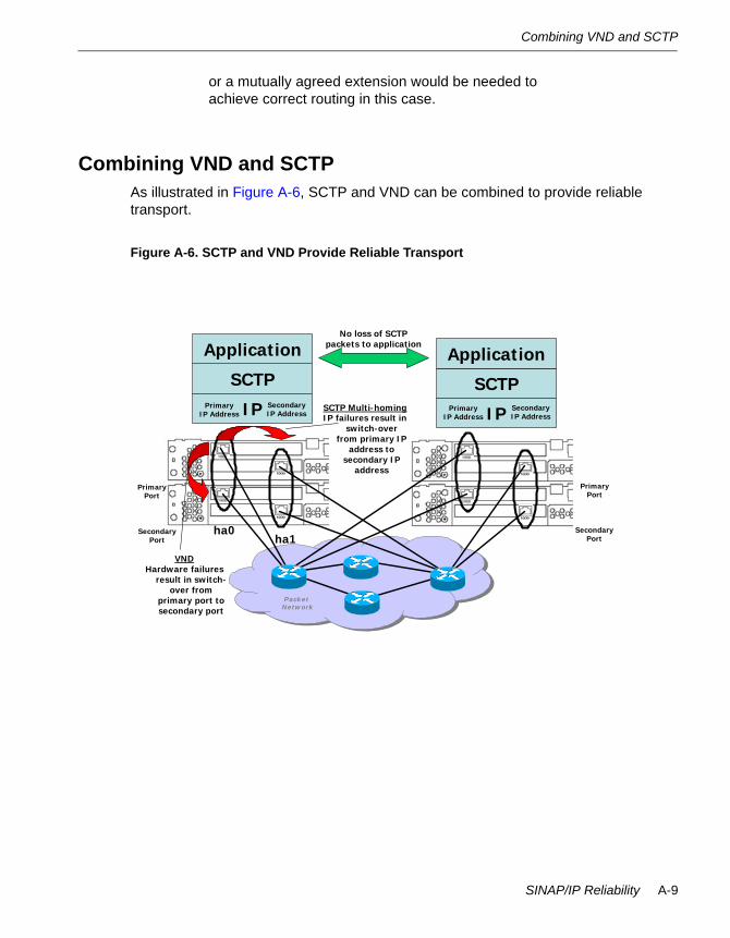
Combining VND and SCTP
or a mutually agreed extension would be needed to achieve correct routing in this case.
Combining VND and SCTPAs illustrated in Figure A-6, SCTP and VND can be combined to provide reliable transport.
Figure A-6. SCTP and VND Provide Reliable Transport
SCTP Multi-homingIP failures result in
switch-over from primary IP
address to secondary IP
address
PacketNetwork
VNDHardware failures
result in switch-over from
primary port to secondary port
SCTP
IP
Application
SCTP
IP
ApplicationNo loss of SCTP
packets to application
PrimaryIP Address
SecondaryIP Address
PrimaryIP Address
SecondaryIP Address
PrimaryPort
PrimaryPort
SecondaryPort
SecondaryPort
ha0ha1
SINAP/IP Reliability A-9

Combining VND and SCTP
A-10 SINAP/IP User’s Guide

Appendix BB-Alarms
This appendix provides a description of the alarms generated by m3uagw, the actions to be taken if they arise, and the source code file generating the alarm.
All alarms are of category GW_EVENT. All events are of type SW_EVENT. Alarms are written to the SINAP alarm log.
For further information on SINAP alarms please see the SINAP/SS7 User’s Guide (R8051).
Alarm Description FormatsTable B-1 lists the components of the alarm descriptions in this appendix.
Table B-1. Alarm Formats
Additionally the following notation conventions are used:
• Text in italics (text) indicates variable message text.
• Vertical bars inside brackets [text version 1 | text version 2] indicate alternate versions of text in an alarm message that is valid for more than one alarm.
Alarm Descriptions and ActionsThe following tables list the alarm event text messages that SINAP/IP can generate.
Message The message text contained in the alarm
Description A short description of the error
Action The action to take to respond to the error message. This is just a short recommended action. In many cases, the action is totally dependent on your specific network environment.
Source The SINAP/IP source code file name that contains the message.
Alarms B-1

Alarm Descriptions and Actions
Message M3UAGW: shmat() failed, errno=error number
Description Could not attach to shared memory segment.
Action Check that SINAP/SS7 has been started. If it has been started, call the CAC.
Source m3uagw_main.c
Message M3UAGW: Broken Pipe
Description This signal has been received by m3uagw. May be non-fatal.
Action Call the CAC.
Source m3uagw_main.c
Message M3UAGW: custom_m3ua_sm_setup_trace() failed
Description Could not set up the trace log.
Action Call the CAC.
Source m3uagw_main.c
Message M3UAGW: variant: number is not supported yet
Description This SINAP-supported variant is not yet supported by the SGC/SGS.
Action None. Or contact SINAP Product Management for a potential enhancement.
Sources m3uagw_main.cm3uagw_callbacks.cm3uagw_ss7ip.c
Message Insufficient Memory to create rkeys
Description Not enough memory.
Action Add more memory.
Source m3uagw_main.c
B-2 SINAP/IP User’s Guide
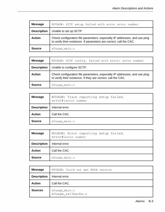
Alarm Descriptions and Actions
Message M3UAGW: SCTP setup failed with error error number
Description Unable to set up SCTP
Action Check configuration file parameters, especially IP addresses, and use ping to verify their existence. If parameters are correct, call the CAC.
Source m3uagw_main.c
Message M3UAGW: SCTP config. failed with error: error number
Description Unable to configure SCTP.
Action Check configuration file parameters, especially IP addresses, and use ping to verify their existence. If they are correct, call the CAC.
Source m3uagw_main.c
Message M3UAGW: Trace reporting setup failed, error#:error number
Description Internal error.
Action Call the CAC.
Source m3uagw_main.c
Message M3UAGW: Error reporting setup failed, error#:error number
Description Internal error.
Action Call the CAC.
Source m3uagw_main.c
Message M3UAGW: Could not get M3UA version
Description Internal error.
Action Call the CAC.
Sources m3uagw_main.cm3uagw_callbacks.c
Alarms B-3

Alarm Descriptions and Actions
Message M3UA protocol parameter setup failed with error: error number
Description Potential configuration error.
Action Check M3UA configuration settings. If they are correct, call the CAC.
Source m3uagw_main.c
Message M3UAGW: Add SGP failed for sgp_id, error#:error number
Description See Message.
Action Check M3UAGW configuration settings. If they are correct, call the CAC.
Source m3uagw_main.c
Message M3UAGW: Config. SGP failed, error#:error number
Description See Message.
Action Check M3UAGW configuration settings, else call the CAC
Source m3uagw_main.c
Message M3UAGW: Add ASP failed, error#:error number
Description See Message.
Action Call the CAC.
Source m3uagw_main.c
Message M3UAGW: Register user part failed, error#:error number
Description See Message.
Action Call the CAC.
Source m3uagw_main.c
B-4 SINAP/IP User’s Guide

Alarm Descriptions and Actions
Message M3UAGW: Add AS:AS number failed, error#:error number
Description See Message.
Action Call the CAC.
Source m3uagw_main.c
Message M3UAGW: stats type stats initialization failed with error #:error number
Description Could not initialize statistics.
Action Call the CAC.
Sources m3uagw_main.cm3uagw_callbacks.c
Message M3UAGW: custom_transport_select() failed
Description Internal error.
Action Call the CAC.
Source m3uagw_main.c
Message M3UAGW: Cannot ascertain local host hostname
Description Potential configuration error.
Action Check configuration. If correct, call the CAC.
Source m3uagw_main.c
Message M3UAGW: custom_set_sinap_fd() failed
Description Internal error.
Action Call the CAC.
Source m3uagw_main.c
Alarms B-5

Alarm Descriptions and Actions
Message M3UAGW: Config. SGP failed, error#:error number
Description Potential configuration error.
Action Check configuration. If correct, call the CAC.
Source m3uagw_main.c
Message M3UAGW: No M3UA connection available to PC:point code
Description There is no available route for this point code.
Action If seen only transitorily after a prohibit or delete action, then no action is required. Otherwise, call the CAC.
Source m3uagw_callbacks.c
Message M3UAGW: Error Sending M3UAGW SCCP Message to:point code. Err:error_number
Description There is no available route for this point code.
Action If seen only transitorily after a prohibit or delete action, then no action is required. Otherwise, call the CAC.
Source m3uagw_callbacks.c
Message M3UAGW: Error: message type:message type not supported
Description Only UnitData and UnitData Service Message types are supported.
Action Stop sending other message types from the remote SS7 node. Or contact SINAP Product Management for a potential enhancement.
Source m3uagw_callbacks.c
Message M3UAGW: ca_get_msg failed. errno=error_number
Description Internal error.
Action Call the CAC.
Source m3uagw_callbacks.c
B-6 SINAP/IP User’s Guide

Alarm Descriptions and Actions
Message M3UAGW: ca_get_msu failed. errno=error_number
Description Internal error.
Action Call the CAC.
Source m3uagw_callbacks.c
Message M3UAGW: Insufficient Memory to create CPC list
Description No memory.
Action Add more memory.
Source m3uagw_callbacks.c
Message M3UAGW: Insufficient Memory to add to CPC List
Description No memory.
Action Add more memory.
Source m3uagw_callbacks.c
Message M3UAGW: Get stats type stats failed with error #: error number
Description Non-Fatal, statistics failure does not stop the mission
Action Call the CAC.
Source m3uagw_callbacks.c
Message M3UAGW: Add SG failed for: sg_id, error#:error number
Description Potential configuration error.
Action Check the configuration. If is correct, call the CAC.
Source m3uagw_callbacks.c
Alarms B-7
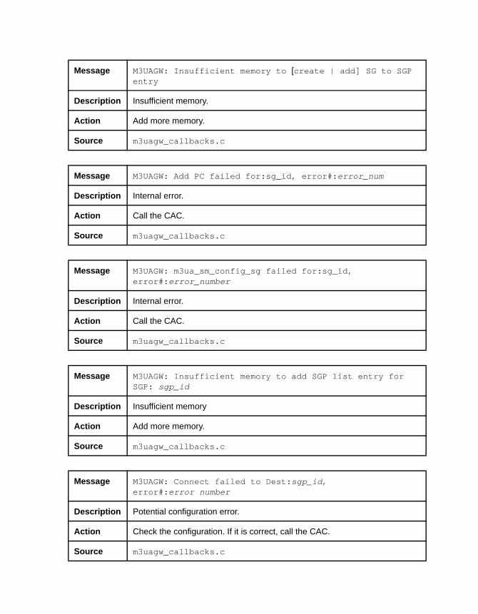
Message M3UAGW: Insufficient memory to [create | add] SG to SGP entry
Description Insufficient memory.
Action Add more memory.
Source m3uagw_callbacks.c
Message M3UAGW: Add PC failed for:sg_id, error#:error_num
Description Internal error.
Action Call the CAC.
Source m3uagw_callbacks.c
Message M3UAGW: m3ua_sm_config_sg failed for:sg_id, error#:error_number
Description Internal error.
Action Call the CAC.
Source m3uagw_callbacks.c
Message M3UAGW: Insufficient memory to add SGP list entry for SGP: sgp_id
Description Insufficient memory
Action Add more memory.
Source m3uagw_callbacks.c
Message M3UAGW: Connect failed to Dest:sgp_id, error#:error number
Description Potential configuration error.
Action Check the configuration. If it is correct, call the CAC.
Source m3uagw_callbacks.c

Alarm Descriptions and Actions
Message M3UAGW: stats type stats [enable | disable] failed with error #:error_num
Description Non-Fatal, statistics enable (or disable) failed.
Action Call the CAC.
Source m3uagw_callbacks.c
Message M3UAGW: A route to the destination:sg_id is [reachable | unreachable]
Description Advisory.
Action None.
Source m3uagw_callbacks.c
Message M3UAGW: m3ua_sm_disconnect failed for route:sgp_id, error:error number
Description API failure.
Action Call the CAC.
Source m3uagw_callbacks.c
Message M3UAGW: Route: sgp_id is disconnected
Description Either intentionally or because of an IP route failure, the SCTP connection has been lost.
Action If traffic is still flowing, no action is required. Otherwise, if disconnection was not intentional, call the CAC.
Source m3uagw_callbacks.c
Alarms B-9
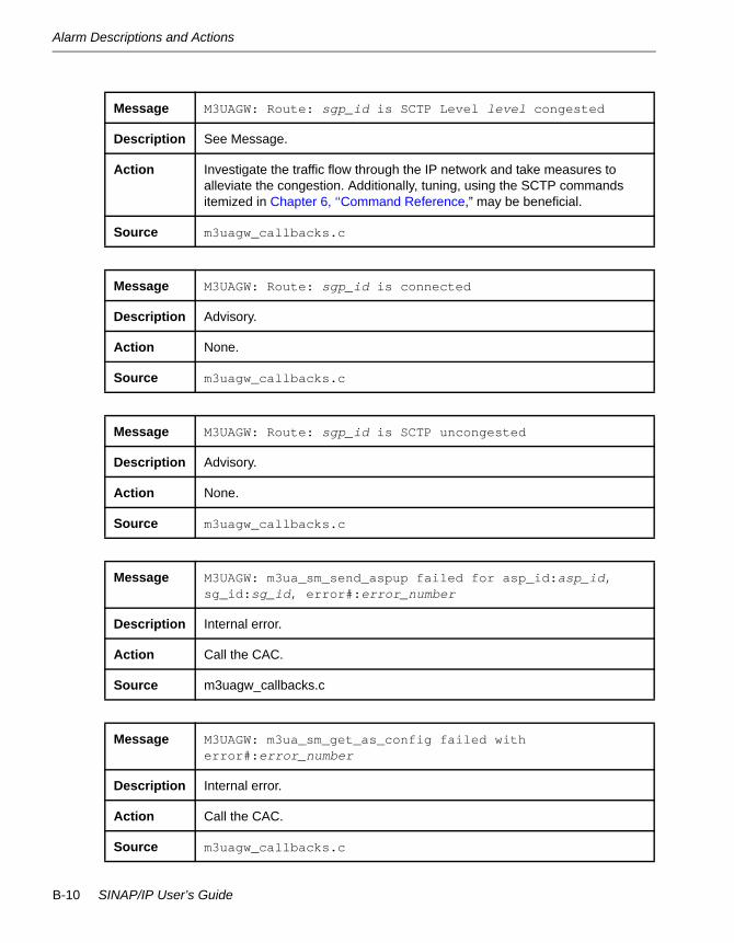
Alarm Descriptions and Actions
Message M3UAGW: Route: sgp_id is SCTP Level level congested
Description See Message.
Action Investigate the traffic flow through the IP network and take measures to alleviate the congestion. Additionally, tuning, using the SCTP commands itemized in Chapter 6, ‘‘Command Reference,” may be beneficial.
Source m3uagw_callbacks.c
Message M3UAGW: Route: sgp_id is connected
Description Advisory.
Action None.
Source m3uagw_callbacks.c
Message M3UAGW: Route: sgp_id is SCTP uncongested
Description Advisory.
Action None.
Source m3uagw_callbacks.c
Message M3UAGW: m3ua_sm_send_aspup failed for asp_id:asp_id, sg_id:sg_id, error#:error_number
Description Internal error.
Action Call the CAC.
Source m3uagw_callbacks.c
Message M3UAGW: m3ua_sm_get_as_config failed with error#:error_number
Description Internal error.
Action Call the CAC.
Source m3uagw_callbacks.c
B-10 SINAP/IP User’s Guide
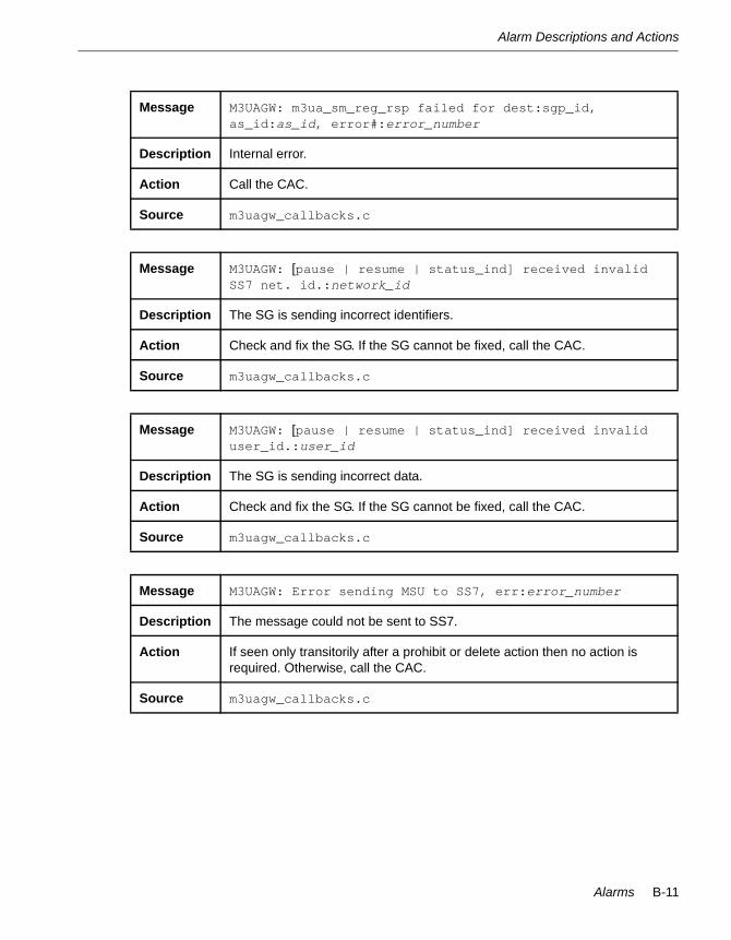
Alarm Descriptions and Actions
Message M3UAGW: m3ua_sm_reg_rsp failed for dest:sgp_id, as_id:as_id, error#:error_number
Description Internal error.
Action Call the CAC.
Source m3uagw_callbacks.c
Message M3UAGW: [pause | resume | status_ind] received invalid SS7 net. id.:network_id
Description The SG is sending incorrect identifiers.
Action Check and fix the SG. If the SG cannot be fixed, call the CAC.
Source m3uagw_callbacks.c
Message M3UAGW: [pause | resume | status_ind] received invalid user_id.:user_id
Description The SG is sending incorrect data.
Action Check and fix the SG. If the SG cannot be fixed, call the CAC.
Source m3uagw_callbacks.c
Message M3UAGW: Error sending MSU to SS7, err:error_number
Description The message could not be sent to SS7.
Action If seen only transitorily after a prohibit or delete action then no action is required. Otherwise, call the CAC.
Source m3uagw_callbacks.c
Alarms B-11

Alarm Descriptions and Actions
Message M3UA reported ERROR:error_number for ASP:asp_id SGP:sgb_id Source:source_file Info:info
Description See Message.
Action If seen only transitorily after a prohibit or delete action then no action is required. Otherwise, call the CAC.
Source m3uagw_callbacks.c
Message M3UAGW: m3ua_sm_send_asp [up | dwn | ac | ia] failed for asp:asp_id, dest_id:dest_id, error#:error_number
Description The message referred to could not be sent.
Action Call the CAC.
Source m3uagw_callbacks.c
Message M3UAGW: m3ua_sm_get_conn_state failed, route:sgp_id, error:error_number
Description Internal error.
Action Call the CAC.
Source m3uagw_callbacks.c
Message M3UAGW: Insufficient memory to create SG to SGP XREF Entry for SG:sg_id
Description See Message.
Action Add more memory.
Source m3uagw_callbacks.c
B-12 SINAP/IP User’s Guide

Alarm Descriptions and Actions
Message M3UAGW: m3ua_sm_connect() failed with error#:error_number for local sp_id:sp_id
Description Potential configuration error.
Action Check IP configuration. If correct, call the CAC.
Source m3uagw_callbacks.c
Message M3UAGW: Route: sgp_id is disconnected
Description SCTP connection has been disconnected.
Action If the route was not deleted intentionally, check the IP network. If the IP network is operational, call the CAC.
Source m3uagw_callbacks.c
Message M3UAGW: m3ua_sm_del_sgp failed for route:sgp_id error:error_number
Description Could not delete the SGP.
Action Call the CAC.
Source m3uagw_callbacks.c
Message M3UAGW: m3ua_sm_del_sg() for:sg_id failed, error#:error_number
Description Could not delete the SG.
Action Call the CAC.
Source m3uagw_callbacks.c
Message m3ua_sm_add_pc(),PC:point_code,SG:sg_id failed with error#:error_number
Description Could not add a point code to this SG.
Action Call the CAC.
Source m3uagw_callbacks.c
Alarms B-13

Alarm Descriptions and Actions
Message M3UAGW: m3ua_sm_config_as(),AS:as_id, failed with error#:error_number
Description On an attempt to change the traffic mode, this call failed.
Action Call the CAC.
Source m3uagw_callbacks.c
Message M3UAGW: Insufficient Memory to create rkey
Description No memory.
Action Add more memory.
Source m3uagw_ss7ip.c
Message M3UAGW: Insufficient Memory to create rkey CPC List
Description No memory.
Action Add more memory.
Source m3uagw_ss7ip.c
Message M3UAGW: Insufficient Memory to add to rkey CPC List
Description No memory.
Action Add more memory.
Source m3uagw_ss7ip.c
Message m3ua_sm_del_as failed, error#:error_number
Description Could not delete an AS.
Action Call the CAC.
Source m3uagw_ss7ip.c
B-14 SINAP/IP User’s Guide

Alarm Descriptions and Actions
Message Add SGP failed for:sgp_id with error:error_number
Description Potential configuration error.
Action Check IP configuration/command lines. If correct, call the CAC.
Source m3uagw_ss7ip.c
Message M3UAGW: Set trace filename failure
Description Internal message.
Action Check disk space availability. If space is available, call the CAC.
Source m3uagw_utils.c
Alarms B-15

Alarm Descriptions and Actions
B-16 SINAP/IP User’s Guide
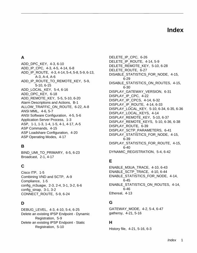
IndexIndex-
AADD_DPC_KEY, 4-3, 6-10ADD_IP_CPC, 4-3, 4-5, 4-14, 6-8ADD_IP_ROUTE, 4-3, 4-14, 5-4, 5-8, 5-9, 6-13,
A-3, A-4, A-6ADD_IP_ROUTE_TO_REMOTE_KEY, 5-9,
5-10, 6-15ADD_LOCAL_KEY, 5-4, 6-16ADD_OPC_KEY, 6-18ADD_REMOTE_KEY, 5-5, 5-10, 6-20Alarm Descriptions and Actions, B-1ALLOW_TRAFFIC_ON_ROUTE, 6-22, A-8ANSI MML, 4-6, 5-7ANSI Software Configuration, 4-5, 5-6Application Server Process, 1-3ASP, 1-1, 1-3, 1-4, 1-5, 4-1, 4-17, A-5ASP Commands, 4-15ASP Loadshare Configuration, 4-20ASP Operating Modes, 4-17
BBIND_UMI_TO_PRIMARY, 6-5, 6-23Broadcast, 2-1, 4-17
CCisco ITP, 1-5Combining VND and SCTP, A-9Compliance, 1-5config_m3uagw, 2-3, 2-4, 3-1, 3-2, 6-6config_sinap, 3-1, 3-2CONNECT_ROUTE, 5-9, 6-24
DDEBUG_LEVEL, 4-3, 4-10, 5-4, 6-25Delete an existing IPSP Endpoint - Dynamic
Registration, 5-9Delete an existing IPSP Endpoint - Static
Registration, 5-10
DELETE_IP_CPC, 6-26DELETE_IP_ROUTE, 4-14, 5-9DELETE_REMOTE_KEY, 5-10, 6-28DELETE_ROUTE, 6-27DISABLE_STATISTICS_FOR_NODE, 4-15,
6-29DISABLE_STATISTICS_ON_ROUTES, 4-15,
6-30DISPLAY_GATEWAY_VERSION, 6-31DISPLAY_IP_CPC, 4-22DISPLAY_IP_CPCS, 4-14, 6-32DISPLAY_IP_ROUTE, 4-14, 6-33DISPLAY_LOCAL_KEY, 5-10, 6-34, 6-35, 6-36DISPLAY_LOCAL_KEYS, 4-14DISPLAY_REMOTE_KEY, 5-10, 6-37DISPLAY_REMOTE_KEYS, 5-10, 6-36, 6-38DISPLAY_ROUTE, 6-39DISPLAY_SCTP_PARAMETERS, 6-41DISPLAY_STATISTICS_FOR_NODE, 4-15,
6-39DISPLAY_STATISTICS_FOR_ROUTE, 4-15,
6-40DYNAMIC_REGISTRATION, 5-4, 6-42
EENABLE_M3UA_TRACE, 4-10, 6-43ENABLE_SCTP_TRACE, 4-10, 6-44ENABLE_STATISTICS_FOR_NODE, 4-14,
6-45ENABLE_STATISTICS_ON_ROUTES, 4-14,
6-46Ethereal, 4-13
GGATEWAY_MODE, 4-2, 5-4, 6-47gathersy, 4-21, 5-16
HHistory file, 4-21, 5-16, 6-3
Index 1
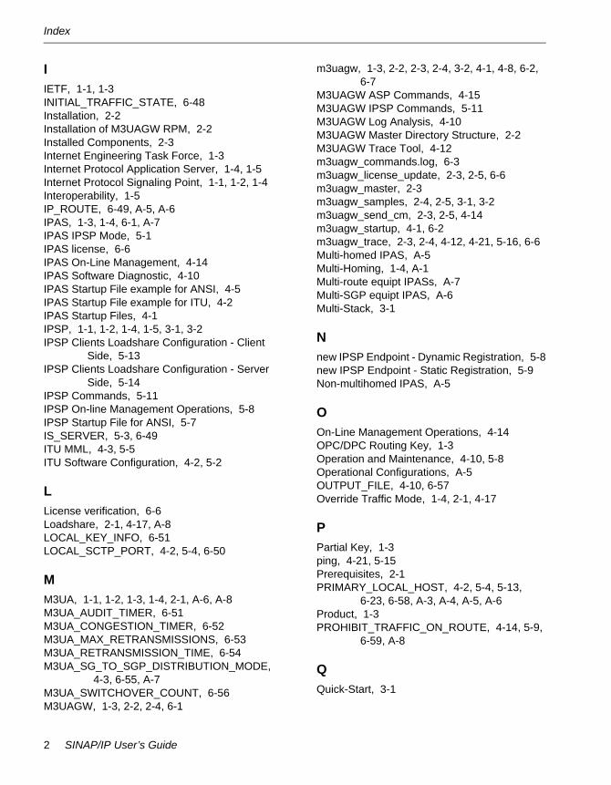
Index
IIETF, 1-1, 1-3INITIAL_TRAFFIC_STATE, 6-48Installation, 2-2Installation of M3UAGW RPM, 2-2Installed Components, 2-3Internet Engineering Task Force, 1-3Internet Protocol Application Server, 1-4, 1-5Internet Protocol Signaling Point, 1-1, 1-2, 1-4Interoperability, 1-5IP_ROUTE, 6-49, A-5, A-6IPAS, 1-3, 1-4, 6-1, A-7IPAS IPSP Mode, 5-1IPAS license, 6-6IPAS On-Line Management, 4-14IPAS Software Diagnostic, 4-10IPAS Startup File example for ANSI, 4-5IPAS Startup File example for ITU, 4-2IPAS Startup Files, 4-1IPSP, 1-1, 1-2, 1-4, 1-5, 3-1, 3-2IPSP Clients Loadshare Configuration - Client
Side, 5-13IPSP Clients Loadshare Configuration - Server
Side, 5-14IPSP Commands, 5-11IPSP On-line Management Operations, 5-8IPSP Startup File for ANSI, 5-7IS_SERVER, 5-3, 6-49ITU MML, 4-3, 5-5ITU Software Configuration, 4-2, 5-2
LLicense verification, 6-6Loadshare, 2-1, 4-17, A-8LOCAL_KEY_INFO, 6-51LOCAL_SCTP_PORT, 4-2, 5-4, 6-50
MM3UA, 1-1, 1-2, 1-3, 1-4, 2-1, A-6, A-8M3UA_AUDIT_TIMER, 6-51M3UA_CONGESTION_TIMER, 6-52M3UA_MAX_RETRANSMISSIONS, 6-53M3UA_RETRANSMISSION_TIME, 6-54M3UA_SG_TO_SGP_DISTRIBUTION_MODE,
4-3, 6-55, A-7M3UA_SWITCHOVER_COUNT, 6-56M3UAGW, 1-3, 2-2, 2-4, 6-1
m3uagw, 1-3, 2-2, 2-3, 2-4, 3-2, 4-1, 4-8, 6-2, 6-7
M3UAGW ASP Commands, 4-15M3UAGW IPSP Commands, 5-11M3UAGW Log Analysis, 4-10M3UAGW Master Directory Structure, 2-2M3UAGW Trace Tool, 4-12m3uagw_commands.log, 6-3m3uagw_license_update, 2-3, 2-5, 6-6m3uagw_master, 2-3m3uagw_samples, 2-4, 2-5, 3-1, 3-2m3uagw_send_cm, 2-3, 2-5, 4-14m3uagw_startup, 4-1, 6-2m3uagw_trace, 2-3, 2-4, 4-12, 4-21, 5-16, 6-6Multi-homed IPAS, A-5Multi-Homing, 1-4, A-1Multi-route equipt IPASs, A-7Multi-SGP equipt IPAS, A-6Multi-Stack, 3-1
Nnew IPSP Endpoint - Dynamic Registration, 5-8new IPSP Endpoint - Static Registration, 5-9Non-multihomed IPAS, A-5
OOn-Line Management Operations, 4-14OPC/DPC Routing Key, 1-3Operation and Maintenance, 4-10, 5-8Operational Configurations, A-5OUTPUT_FILE, 4-10, 6-57Override Traffic Mode, 1-4, 2-1, 4-17
PPartial Key, 1-3ping, 4-21, 5-15Prerequisites, 2-1PRIMARY_LOCAL_HOST, 4-2, 5-4, 5-13,
6-23, 6-58, A-3, A-4, A-5, A-6Product, 1-3PROHIBIT_TRAFFIC_ON_ROUTE, 4-14, 5-9,
6-59, A-8
QQuick-Start, 3-1
2 SINAP/IP User’s Guide
Index
RREADME, 2-5RECONNECT_TIMER, 6-60REMOTE_KEY_INFO, 6-61Routing Key, 1-3Routing Key Status, 5-10rpm, 2-2
SSCTP, 1-1, 1-2, 1-3, A-2, A-6SCTP Multi-home Failover Sample - IPAS
Setup, A-5SCTP Multi-Homing, A-2SCTP_ASSOC_MAX_RETRANS, 6-61, A-4,
A-5SCTP_BUNDLING_TIME, 6-62SCTP_FRAGMENTATION_ALLOWED, 6-63SCTP_HEARTBEAT, 6-64, A-4, A-5SCTP_HIGH_CONG_LEVEL, 6-65SCTP_LOW_CONG_LEVEL, 6-66SCTP_MAX_ENDPOINTS, 6-67SCTP_MAX_RX_BUFFERS, 6-67SCTP_MAX_TX_BUFFERS, 6-69SCTP_NO_CONG_LEVEL, 6-70SCTP_PATH_MAX_RETRANS, 6-71, A-4, A-5SCTP_RTO_ALPHA, 6-72SCTP_RTO_BETA, 6-73SCTP_RTO_INIT, 6-77, A-5SCTP_RTO_MAX, 6-75, A-5SCTP_RTO_MIN, 6-76, A-5SECONDARY_LOCAL_HOST, 6-77, A-3, A-4,
A-5, A-6send_cm, 3-2SEP, 4-4, 4-8SG, 1-1, 1-3, 1-4, 4-14, A-6, A-7SGP, 1-4, 2-1, 4-14, A-3, A-7SGPs, 2-1SGs, 2-1SHUTDOWN, 4-14, 6-78Shutdown, 4-10Signaling Gateway, 1-1, 1-4Signaling Gateway Process, 1-4, 2-1, A-3Signaling Transport, 1-3Signalling Gateway, 1-3SIGTRAN, 1-1, 1-3SINAP/IP
prerequisites, 2-1SINAP/IP Configuration Support, 1-5
SINAP/SS7 nodesANSI
configuring, 3-2creating, 3-2
ITUconfiguring, 3-1creating, 3-1
SINAP_APPLICATION_NAME, 6-79sinap_license, 6-6sinap_license_update, 6-6SINAP_QUEUE_SIZE, 6-80SS7links file, 3-1, 3-2SS7-over-IP, 1-1Start m3uagw process, 3-2start_sinap, 4-8Startup, 4-7Startup File examples for ITU, 5-2Stratus ft Linux Installation, 2-2Stream Control Transmission Protocol, 1-1, 1-3
Ttcrecv, 4-8tcsend, 4-9Traffic, 4-8Traffic using tcsend/tcrecv, 3-3Traffic using tcsend/tcrecv - ITU, 3-3Troubleshooting, 4-21, 5-15Two ASP OPC/DPC Failover
Configuration, 4-17
UUMI_PORT, 6-5
VVirtual Network Device (VND), A-1
Index 3

Index
4 SINAP/IP User’s Guide