jbm is a multi unit, multi product group with extensive and diversified interests in engineering and...
TRANSCRIPT

INDUSTRIAL TRAINING AT

Overview Of JBML
JBM is a multi unit, multi product group with extensive and diversified interests in engineering and precision tooling, dies, chemicals, textiles and facilities spread over different parts of the country. The JBM engineering group deals in a broad range of sheet metal assemblies, die casting components and forging for the domestic and the export market. JAY BHARAT MARUTI LIMITED, set up in 1987, is the largest joint venture of MARUTI UDYOG LIMITED, in collaboration with SUZUKI MOTOR CORPORATIONOF JAPAN. It was started by Mr Surender Kumar Arya of Bombay.
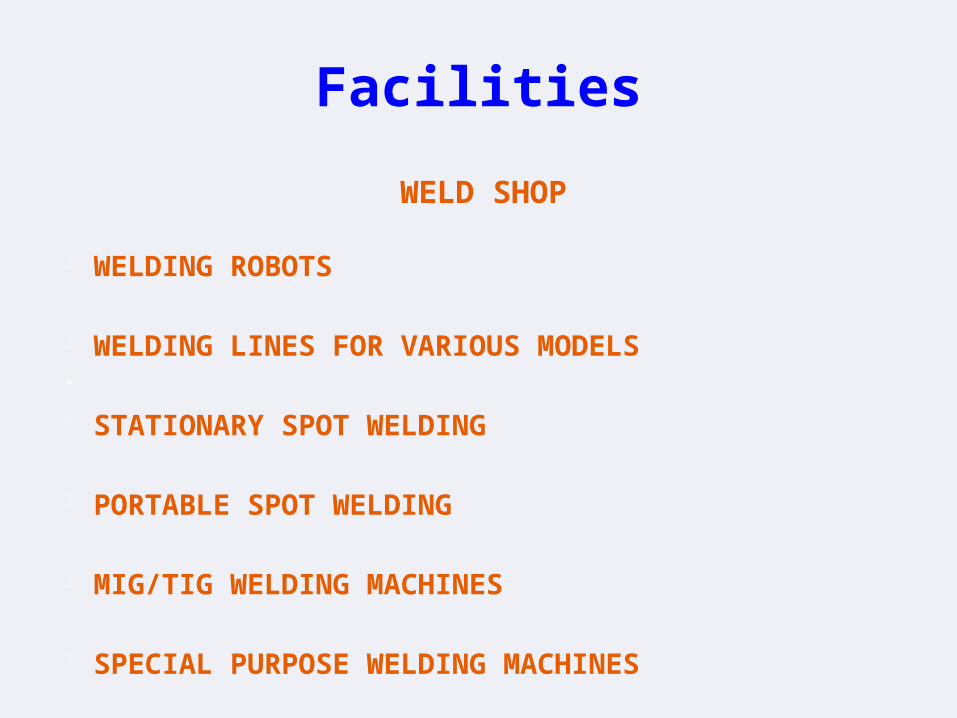
Facilities
WELD SHOP
• WELDING ROBOTS
• WELDING LINES FOR VARIOUS MODELS
• STATIONARY SPOT WELDING
• PORTABLE SPOT WELDING
• MIG/TIG WELDING MACHINES
• SPECIAL PURPOSE WELDING MACHINES
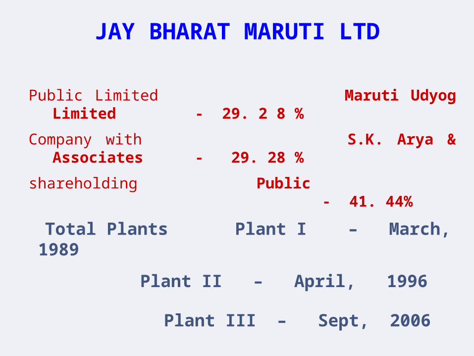
JAY BHARAT MARUTI LTD
Public Limited Maruti Udyog Limited - 29. 2 8 %
Company with S.K. Arya & Associates - 29. 28 %
shareholding Public - 41. 44%
Total Plants Plant I – March, 1989
Plant II – April, 1996 Plant III – Sept, 2006
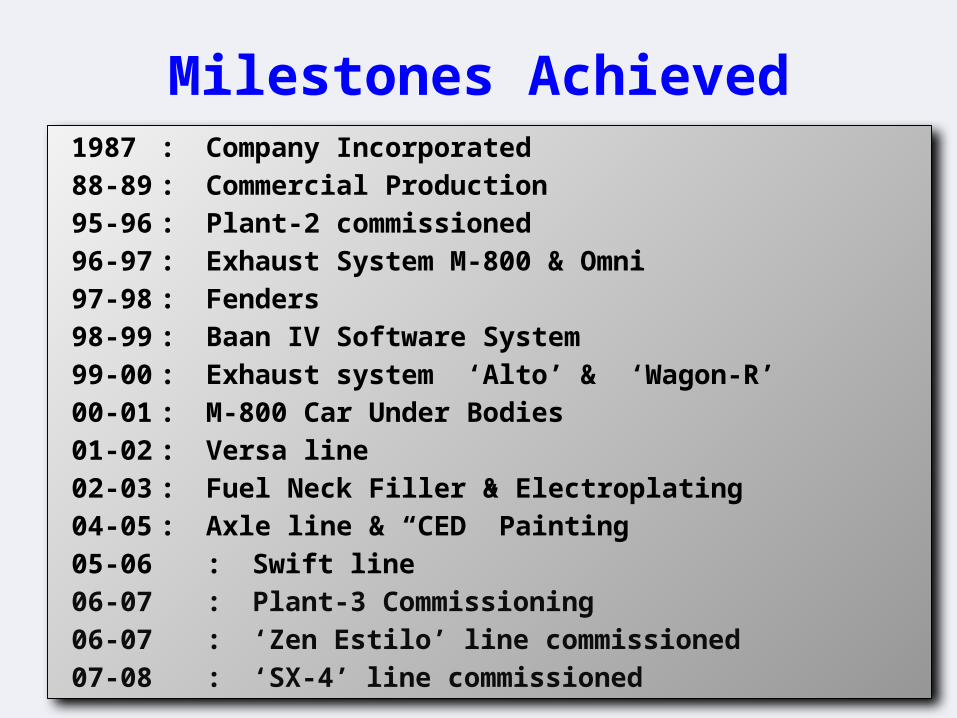
Milestones Achieved1987 : Company Incorporated88-89 : Commercial Production 95-96 : Plant-2 commissioned96-97 : Exhaust System M-800 & Omni97-98 : Fenders98-99 : Baan IV Software System 99-00 : Exhaust system ‘Alto’ & ‘Wagon-R’00-01 : M-800 Car Under Bodies01-02 : Versa line 02-03 : Fuel Neck Filler & Electroplating04-05 : Axle line & “CED” Painting05-06 : Swift line06-07 : Plant-3 Commissioning06-07 : ‘Zen Estilo’ line commissioned07-08 : ‘SX-4’ line commissioned
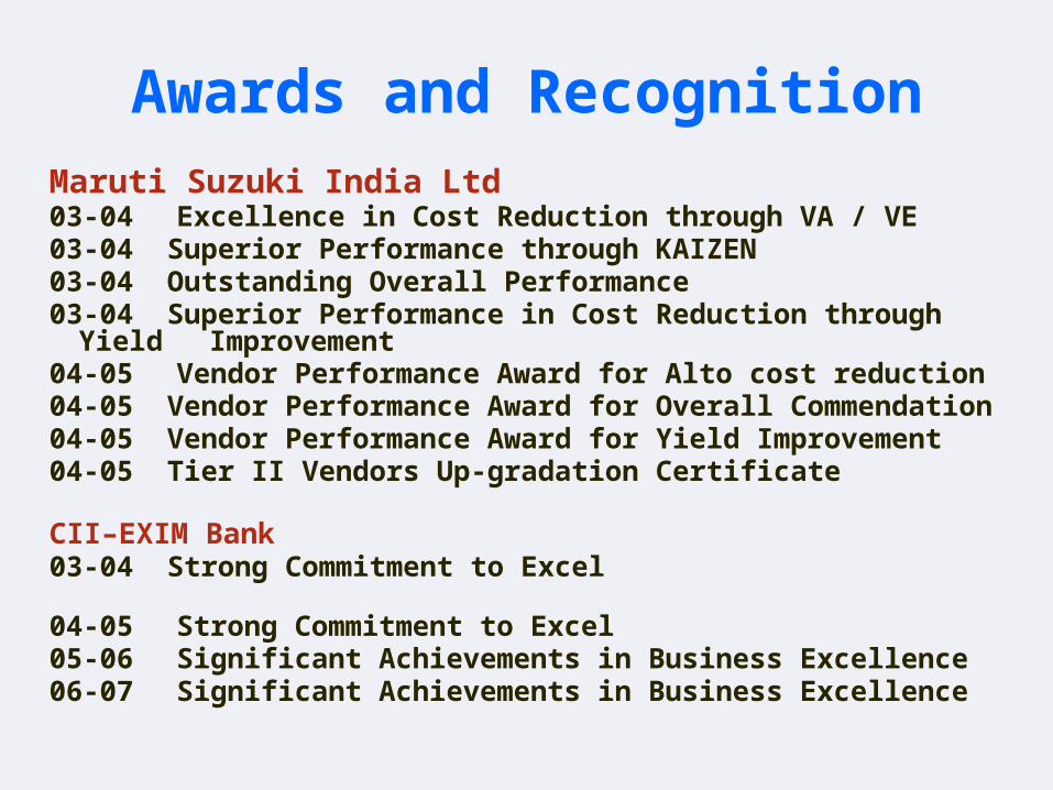
Awards and RecognitionMaruti Suzuki India Ltd 03-04 Excellence in Cost Reduction through VA / VE 03-04 Superior Performance through KAIZEN03-04 Outstanding Overall Performance03-04 Superior Performance in Cost Reduction through Yield
Improvement04-05 Vendor Performance Award for Alto cost reduction04-05 Vendor Performance Award for Overall Commendation04-05 Vendor Performance Award for Yield Improvement04-05 Tier II Vendors Up-gradation Certificate
CII–EXIM Bank03-04 Strong Commitment to Excel 04-05 Strong Commitment to Excel 05-06 Significant Achievements in Business Excellence 06-07 Significant Achievements in Business Excellence

EuropeThyssen Krupp
ThailandThai SummitUnion Autoparts
Geographic tie ups for world class technology
PARTNERS WORLDWIDE
IndiaMaruti Udyog
JapanBellsonicaDaiwa ExcelHamamatsu PipeFutaba Co.JFEMetal OneYorozu

Customers
EXHAUST SYSTEM
Introduction
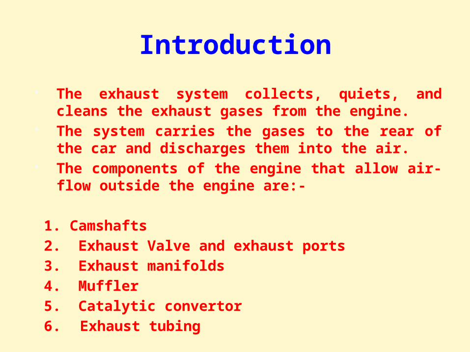
The exhaust system collects, quiets, and cleans the exhaust gases from the engine.
The system carries the gases to the rear of the car and discharges them into the air.
The components of the engine that allow air-flow outside the engine are:-
1. Camshafts 2. Exhaust Valve and exhaust ports 3. Exhaust manifolds 4. Muffler 5. Catalytic convertor 6. Exhaust tubing
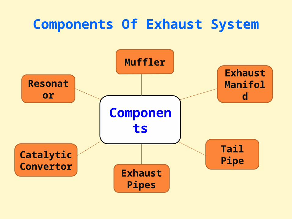
Components Of Exhaust System
Components
Exhaust Pipes
Muffler
Tail Pipe
Resonator
Catalytic Convertor
Exhaust Manifold
Exhaust manifold
1. It is a set of pipes that collect gases from the combustion chamber and passes them to the exhaust pipes.
2. They are made up of gray cast iron or nodular cast iron.
3. They are mounted to the cylinder head’s exhaust ports. When the engine works hard or has a lean air-fuel mixture, the exhaust manifold runs red hot.
4. The exhaust manifolds have a gasket between them and the cylinder head. Gaskets are meant to prevent leakage of air/gases between the manifold and cylinder head.
Headers
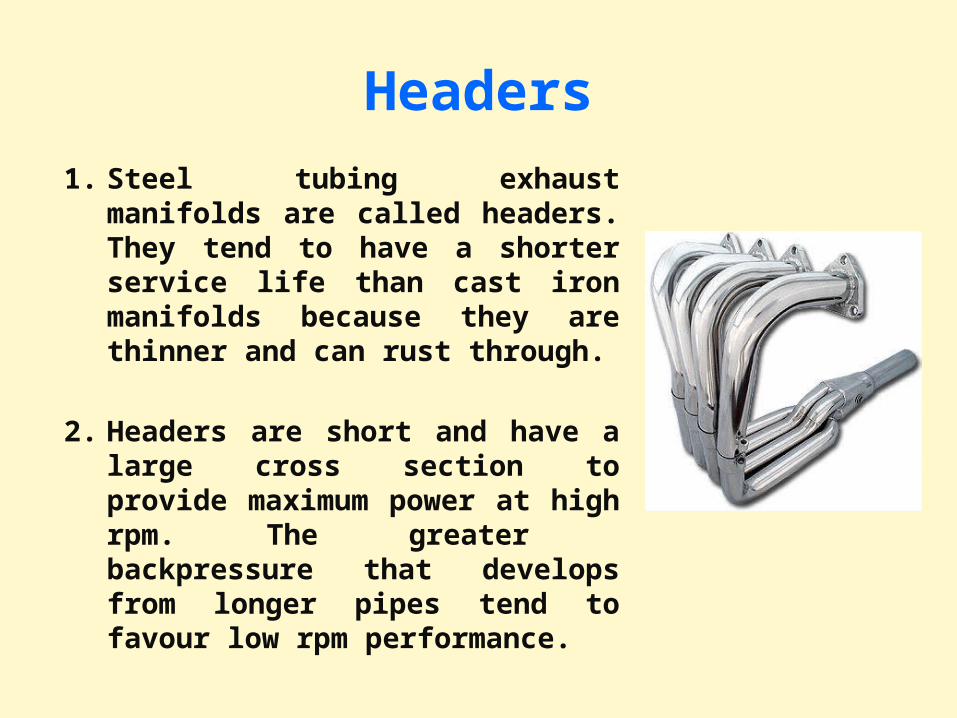
1. Steel tubing exhaust manifolds are called headers. They tend to have a shorter service life than cast iron manifolds because they are thinner and can rust through.
2. Headers are short and have a large cross section to provide maximum power at high rpm. The greater backpressure that develops from longer pipes tend to favour low rpm performance.
Muffler
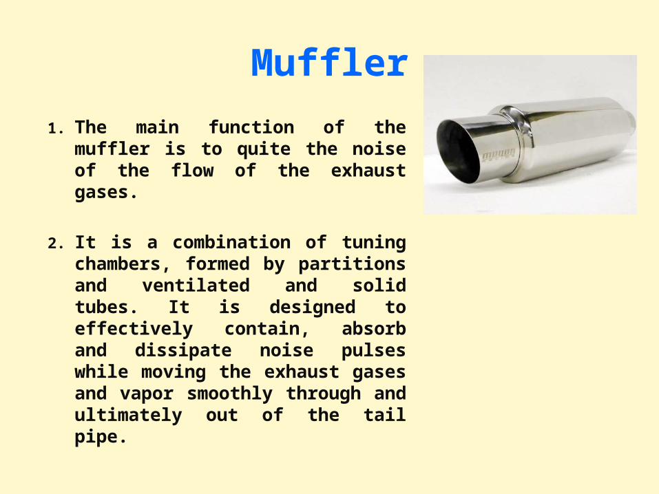
1. The main function of the muffler is to quite the noise of the flow of the exhaust gases.
2. It is a combination of tuning chambers, formed by partitions and ventilated and solid tubes. It is designed to effectively contain, absorb and dissipate noise pulses while moving the exhaust gases and vapor smoothly through and ultimately out of the tail pipe.
3. The location of a muffler varies considerably depending on the vehicle model, but most mufflers are located toward the rear of the vehicle. The muffler can assume many shapes from round to oval, to custom stamped.
4. The muffler reduces the noise of exhaust by muffling the sound waves created by the opening and closing of the exhaust valves. When the exhaust valve opens, it discharges the gases at very high pressure into the exhaust pipe which itself is at low pressure. This creates a sound wave which the muffler must silence. The wave energy is converted into heat by passing the exhaust gases and it’s accompanying wave pattern through perforated tubes and tuning chambers.
Muffler Construction
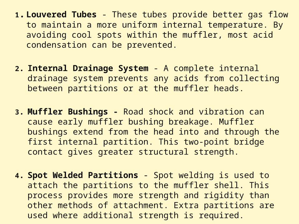
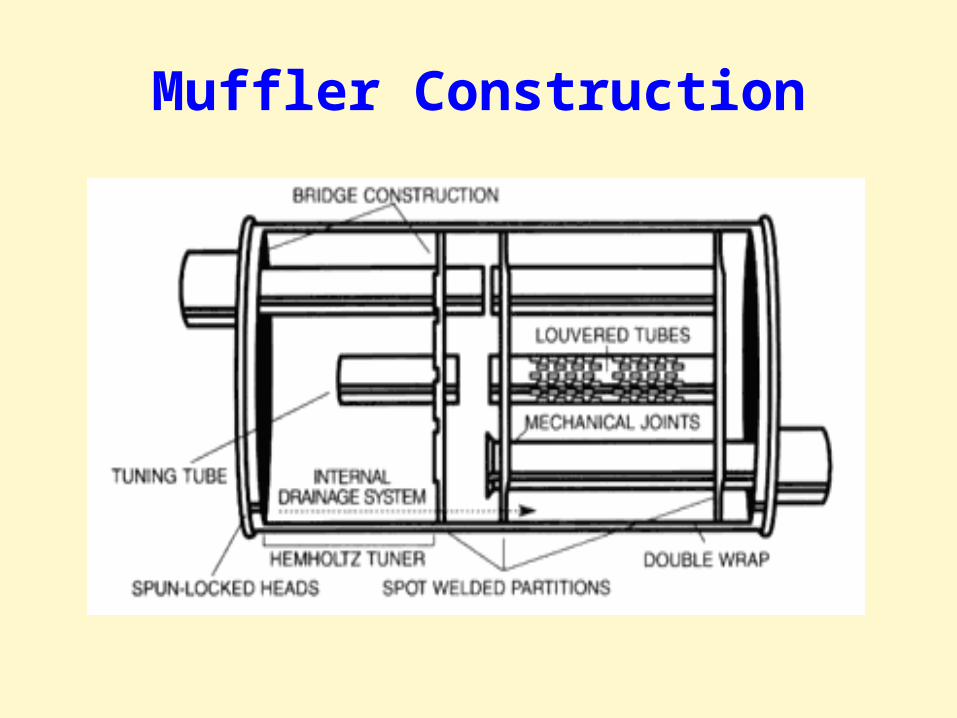
1. Louvered Tubes - These tubes provide better gas flow to maintain a more uniform internal temperature. By avoiding cool spots within the muffler, most acid condensation can be prevented.
2. Internal Drainage System - A complete internal drainage system prevents any acids from collecting between partitions or at the muffler heads.
3. Muffler Bushings - Road shock and vibration can cause early muffler bushing breakage. Muffler bushings extend from the head into and through the first internal partition. This two-point bridge contact gives greater structural strength.
4. Spot Welded Partitions - Spot welding is used to attach the partitions to the muffler shell. This process provides more strength and rigidity than other methods of attachment. Extra partitions are used where additional strength is required.
Exhaust System Pipings
1. The Exhaust pipe carries the collected gases and vapor from the exhaust manifold or header to another component further downstream in the exhaust system.
2. The "Y" pipe is an exhaust pipe, which connects both exhaust headers of a "V" engine to form a single exhaust system. It may also be used to split a single exhaust system into a dual exhaust system.
3. Balance pipes are used in many dual exhaust systems to merge sound pulses from left-hand and right-hand sources. This helps reduce harsh exhaust sounds, equalizes muffler and tail pipe life, and can aid in improving mid-range torque output of the engine.
4. A "Crossover" pipe connects one exhaust header to the other, thus creating the start of a single exhaust system combining multiple exhaust outlets into one.
Catalytic Convertor
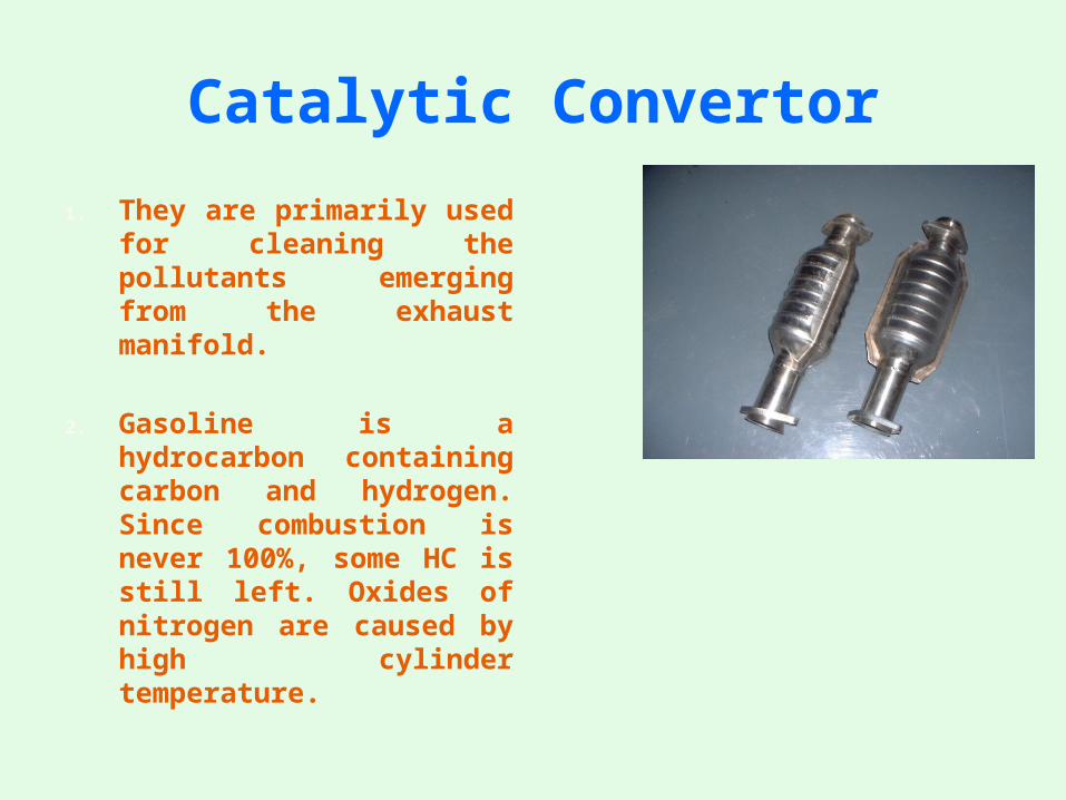
1. They are primarily used for cleaning the pollutants emerging from the exhaust manifold.
2. Gasoline is a hydrocarbon containing carbon and hydrogen. Since combustion is never 100%, some HC is still left. Oxides of nitrogen are caused by high cylinder temperature.
3. Within the stainless steel shell of an aftermarket catalytic converter lies a substrate that's coated with a combination of platinum, palladium, and sometimes rhodium. These three chemicals are frequently called precious, or noble, metals. Typically, oxidation converters are loaded with platinum and palladium. Three-way and three-way-plus converters are loaded with platinum, palladium, and rhodium.
4. When the exhaust gas comes in contact with the precious metals or catalyst, a chemical reaction takes place that weakens the bonds of the polluting chemicals and allows them to easily convert into the more desirable by-products of combustion.
5. There are three types of convertor:- oxidation, three-way and three-way plus oxidation convertor.
2- Way Convertor
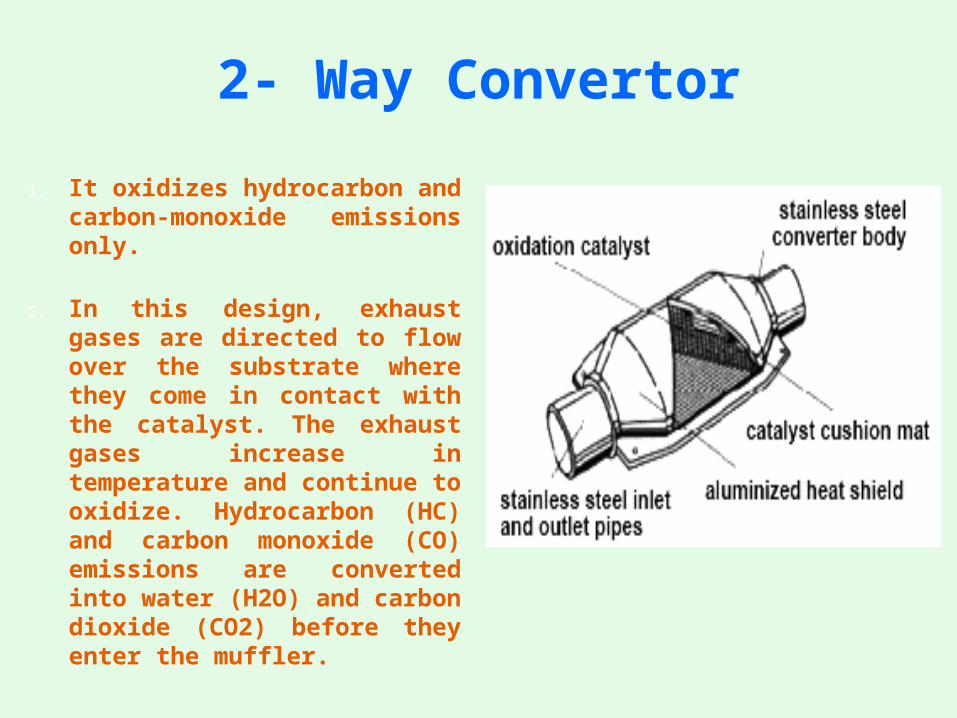
1. It oxidizes hydrocarbon and carbon-monoxide emissions only.
2. In this design, exhaust gases are directed to flow over the substrate where they come in contact with the catalyst. The exhaust gases increase in temperature and continue to oxidize. Hydrocarbon (HC) and carbon monoxide (CO) emissions are converted into water (H2O) and carbon dioxide (CO2) before they enter the muffler.
3-Way Convertor
1. These converters reduce NOx emissions as well as oxidize hydrocarbon and carbon monoxide.
2. Inside, a 3-way without air converter looks like a 2-way converter. But, the 3-way without air substrate is coated with rhodium and palladium.
3. If an engine's exhaust is high in hydrocarbons and carbon monoxide, an air pump and tube feed extra oxygen directly to the converter. Inside a 3-way with air-injection, there are two substrates.
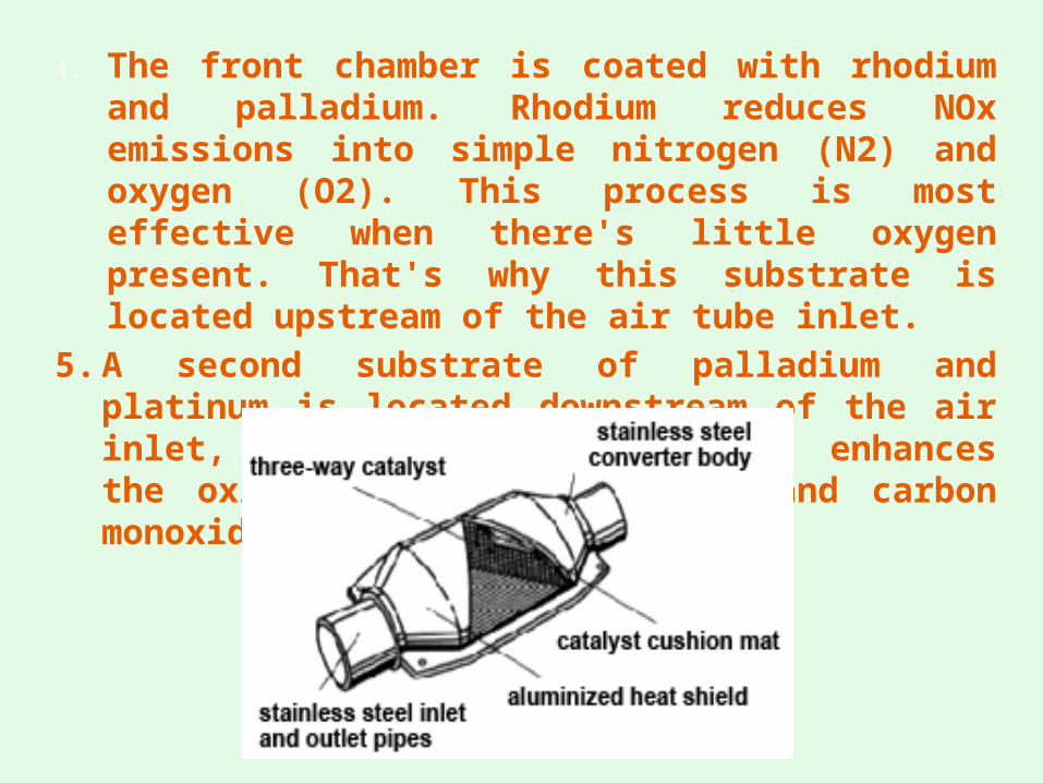
4. The front chamber is coated with rhodium and palladium. Rhodium reduces NOx emissions into simple nitrogen (N2) and oxygen (O2). This process is most effective when there's little oxygen present. That's why this substrate is located upstream of the air tube inlet.
5. A second substrate of palladium and platinum is located downstream of the air inlet, so the increased oxygen enhances the oxidation of hydrocarbons and carbon monoxide.
Convertor Failure
1. No matter what the converter design, they all fail for the same reasons. Since there are no moving parts in a converter, the most common cause of failure is contamination.
2. When overly rich fuel mixtures or raw fuel is introduced into a converter, its temperature can rise to the point that its substrate will simply meltdown. This is known as thermal failure. Thermal failure will deactivate the catalyst and, in extreme cases, block exhaust flow through the unit.
3. Thermal shock occurs when an overheated converter is fed cold raw fuel or comes in contact with winter elements. The ceramic substrate cools too rapidly and contracts unevenly. It starts to crack and break up. Normal exhaust system vibration will cause it to disintegrate even further.
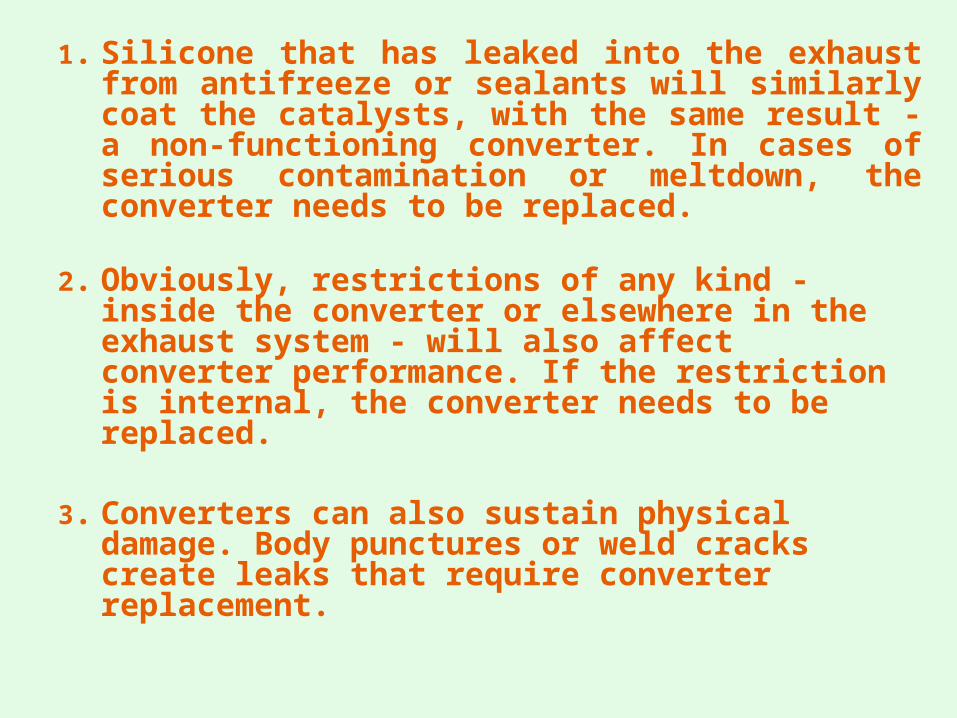
1. Silicone that has leaked into the exhaust from antifreeze or sealants will similarly coat the catalysts, with the same result - a non-functioning converter. In cases of serious contamination or meltdown, the converter needs to be replaced.
2. Obviously, restrictions of any kind - inside the converter or elsewhere in the exhaust system - will also affect converter performance. If the restriction is internal, the converter needs to be replaced.
3. Converters can also sustain physical damage. Body punctures or weld cracks create leaks that require converter replacement.
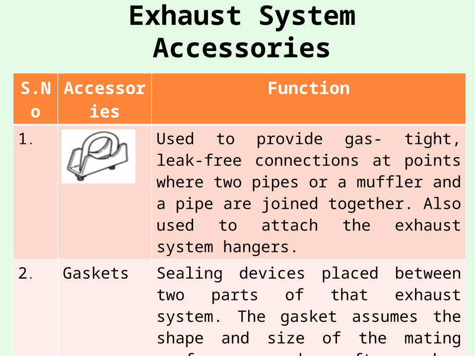
Exhaust System Accessories
S.No Accessories Function
1. Clamp Used to provide gas- tight, leak-free connections at points where two pipes or a muffler and a pipe are joined together. Also used to attach the exhaust system hangers.
2. Gaskets Sealing devices placed between two parts of that exhaust system. The gasket assumes the shape and size of the mating surfaces and often has provisions for securing via multiple bolt holes punched through the material. These devices may be made of composition materials, formed metal, or a combination of the two materials.
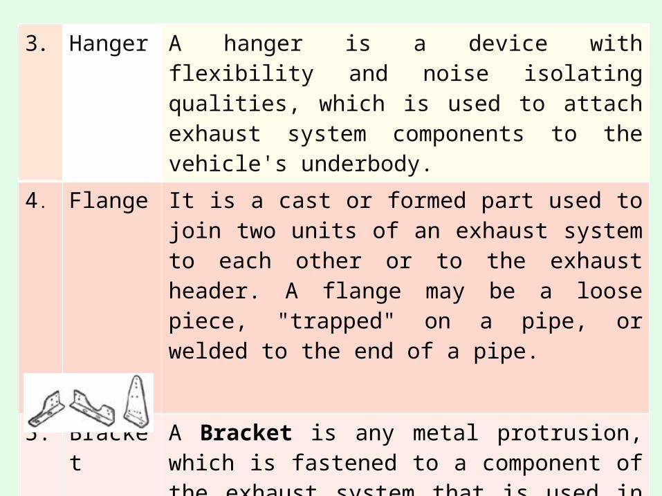
3. Hanger A hanger is a device with flexibility and noise isolating qualities, which is used to attach exhaust system components to the vehicle's underbody.
4. Flange It is a cast or formed part used to join two units of an exhaust system to each other or to the exhaust header. A flange may be a loose piece, "trapped" on a pipe, or welded to the end of a pipe.
5. Bracket A Bracket is any metal protrusion, which is fastened to a component of the exhaust system that is used in suspending or reinforcing the exhaust system. These devices are generally made of metal stampings, and often use rubber components within their structure for vibration control.
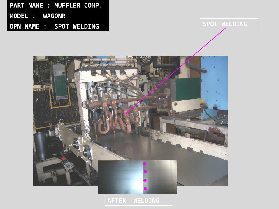
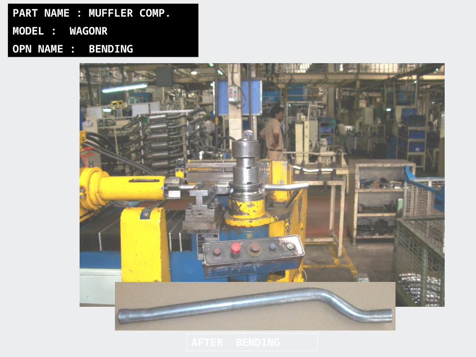
PART NAME : MUFFLER COMP.
MODEL : WAGONR
OPN NAME : SPOT WELDING SPOT WELDING
AFTER WELDING
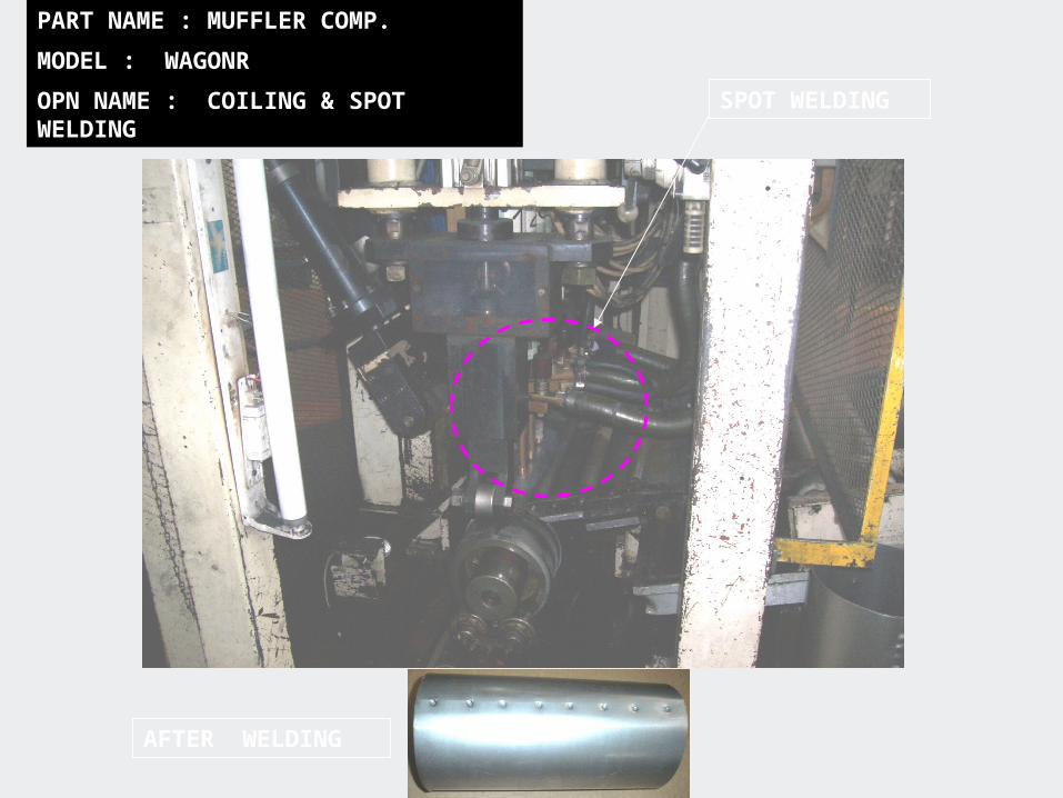
PART NAME : MUFFLER COMP.
MODEL : WAGONR
OPN NAME : COILING & SPOT WELDING SPOT WELDING
AFTER WELDING
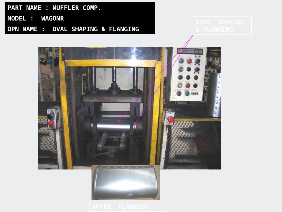
PART NAME : MUFFLER COMP.
MODEL : WAGONR
OPN NAME : OVAL SHAPING & FLANGINGOVAL SHAPING & FLANGING
AFTER FLANGING

PART NAME : MUFFLER COMP.
MODEL : WAGONR
OPN NAME : SPOT WELDING
AFTER WELDING
SPOT WELD SHEEL+COVER
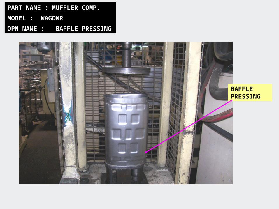
PART NAME : MUFFLER COMP.
MODEL : WAGONR
OPN NAME : BAFFLE PRESSING
BAFFLE PRESSING
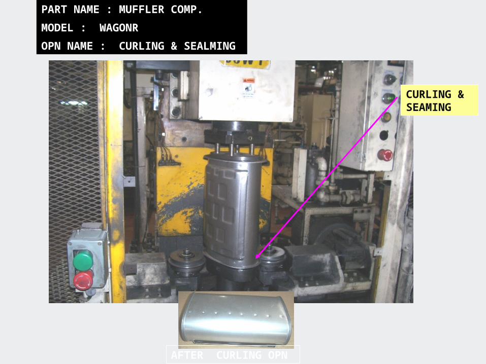
PART NAME : MUFFLER COMP.
MODEL : WAGONR
OPN NAME : CURLING & SEALMING
CURLING & SEAMING
AFTER CURLING OPN
PART NAME : MUFFLER COMP.
MODEL : WAGONR
OPN NAME : BENDING
AFTER BENDING
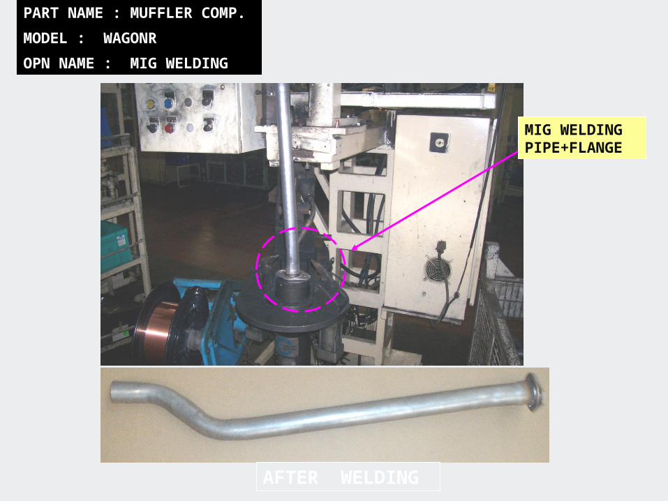
PART NAME : MUFFLER COMP.
MODEL : WAGONR
OPN NAME : MIG WELDING
MIG WELDING PIPE+FLANGE
AFTER WELDING
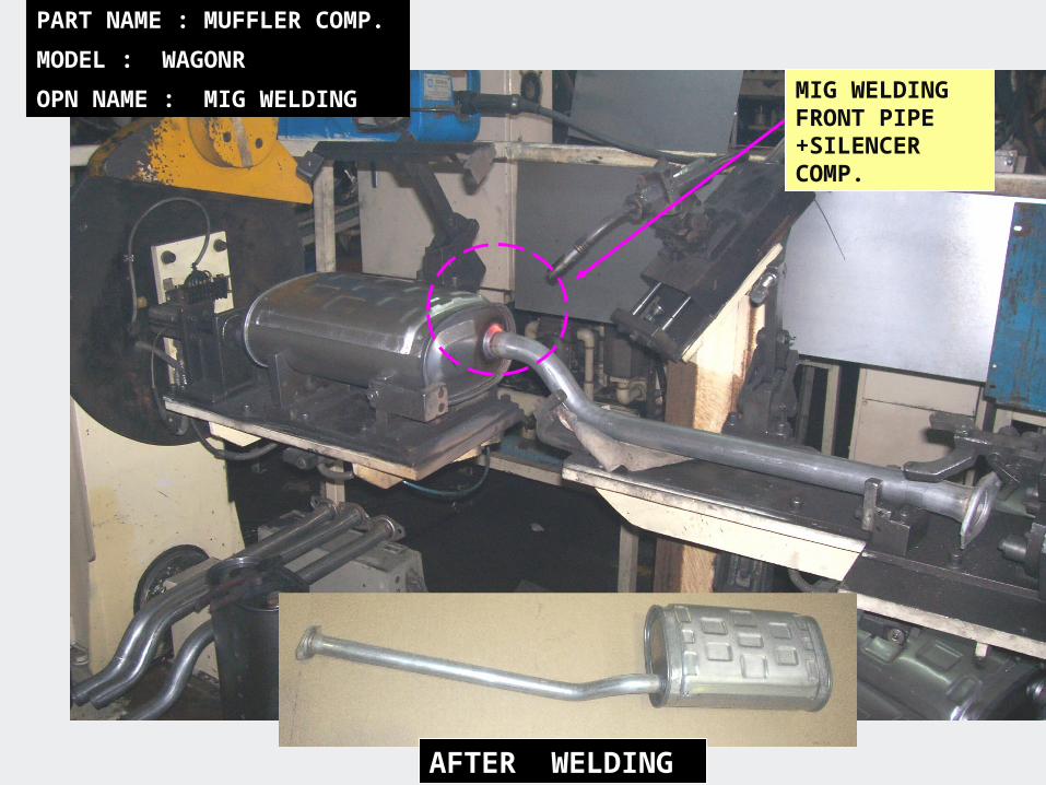
MIG WELDING FRONT PIPE +SILENCER COMP.
PART NAME : MUFFLER COMP.
MODEL : WAGONR
OPN NAME : MIG WELDING
AFTER WELDING
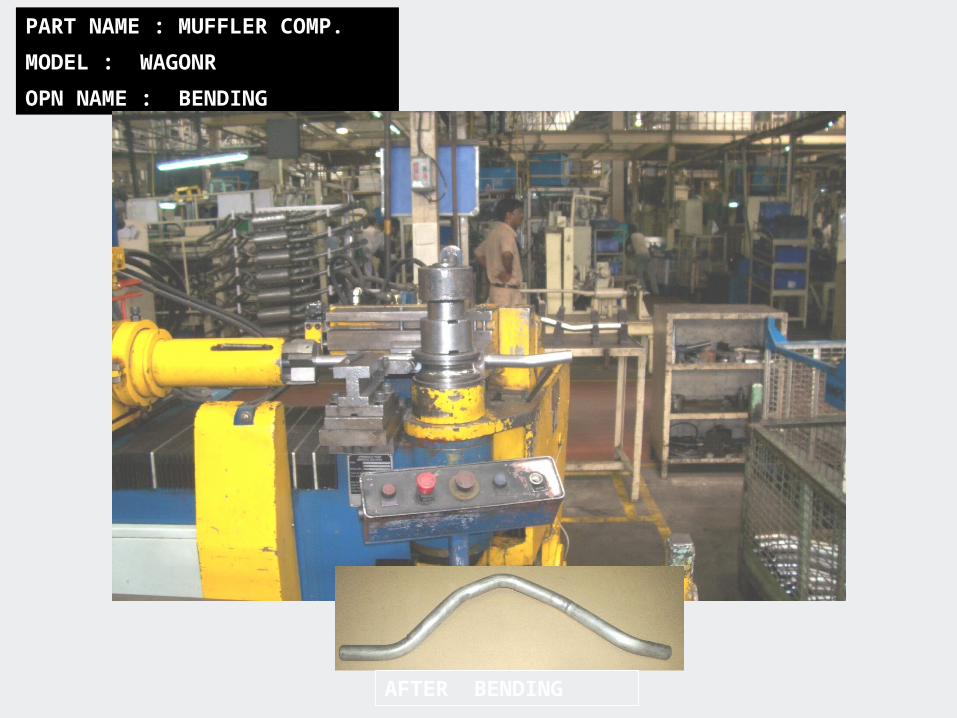
PART NAME : MUFFLER COMP.
MODEL : WAGONR
OPN NAME : BENDING
AFTER BENDING
PART NAME : MUFFLER COMP.
MODEL : WAGONR
OPN NAME : MIG WELDING
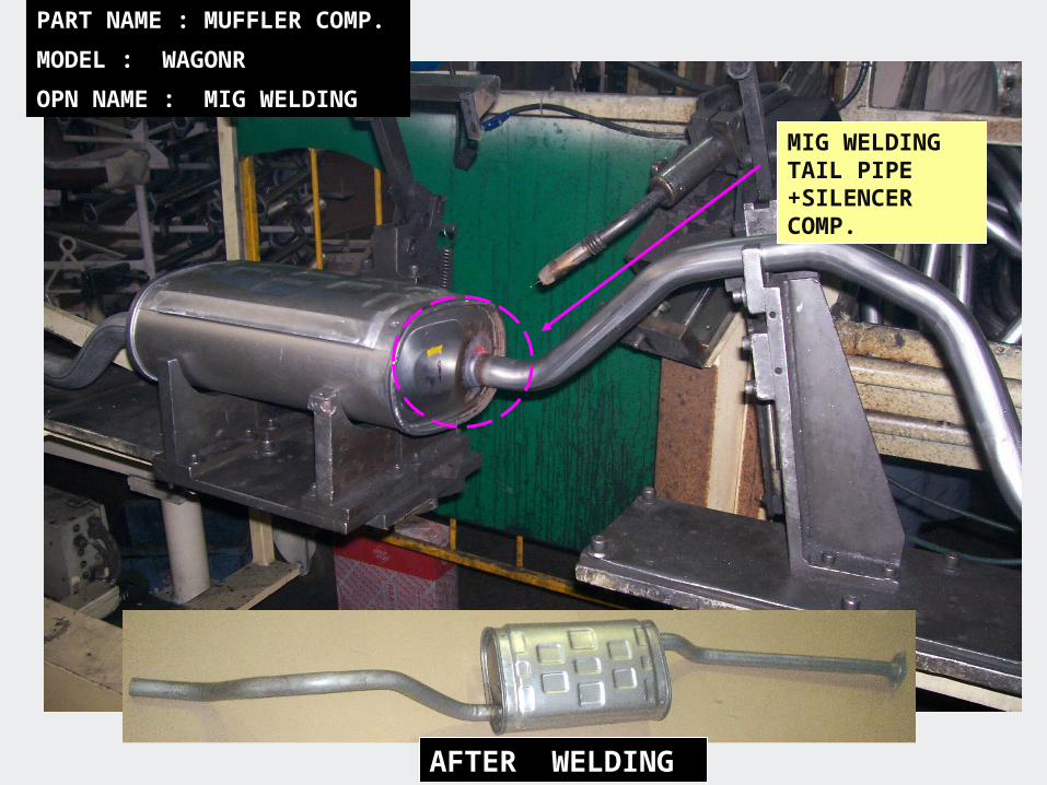
MIG WELDING TAIL PIPE +SILENCER COMP.
AFTER WELDING
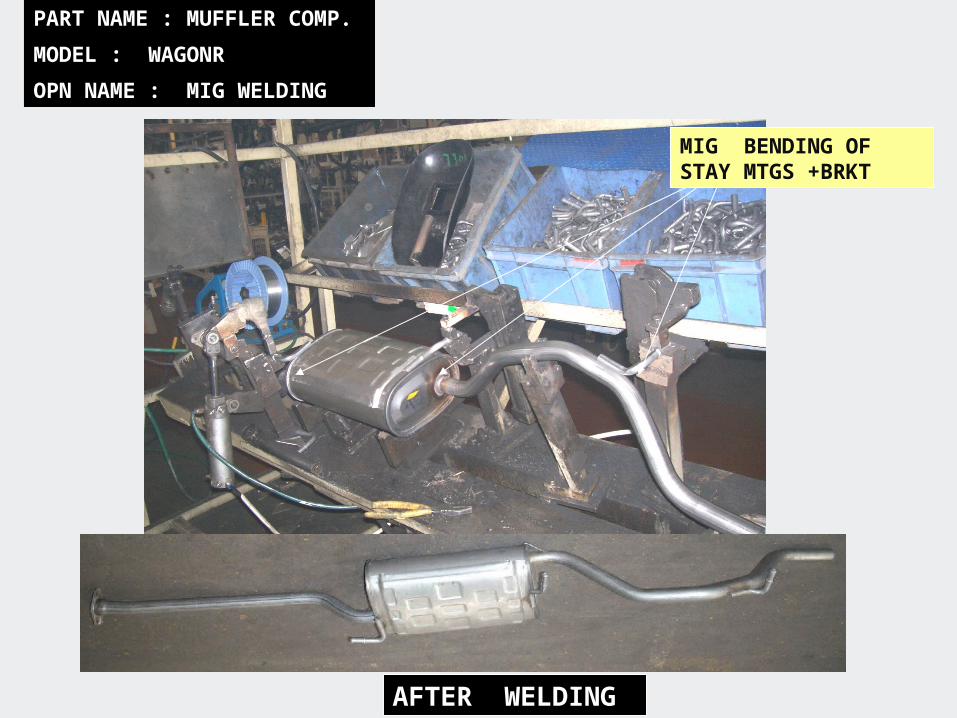
PART NAME : MUFFLER COMP.
MODEL : WAGONR
OPN NAME : MIG WELDING
MIG BENDING OF STAY MTGS +BRKT
AFTER WELDING
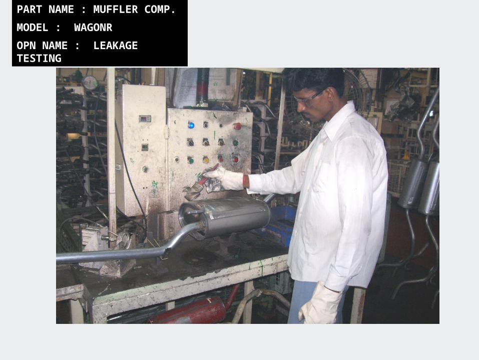
PART NAME : MUFFLER COMP.
MODEL : WAGONR
OPN NAME : LEAKAGE TESTING
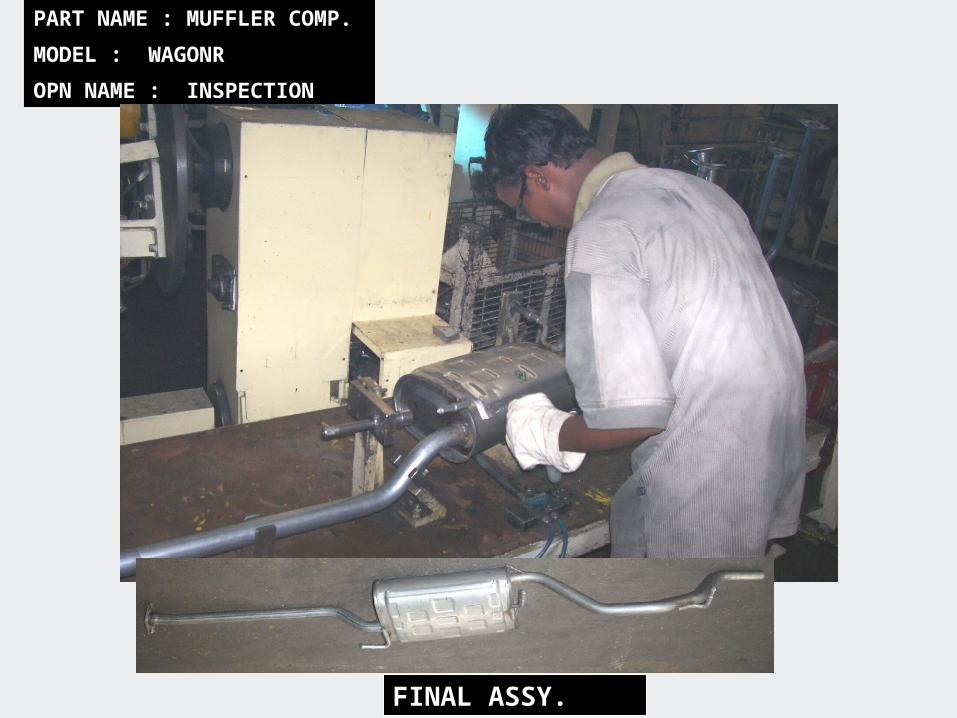
PART NAME : MUFFLER COMP.
MODEL : WAGONR
OPN NAME : INSPECTION
FINAL ASSY.

THANK YOU