- interempresas the y-axis which uses orc can be located at the center. through holes have been made...
TRANSCRIPT

NZX 1500
NZX 2000
High-Precision, High-Efficiency Multi-Axis Turning Center
NZX 1500 / NZX 2000
www.dmgmori.com

Seeking the last word in mass production machines
High-efficiency multi-axis turning center enabling the ultimate in process integration
with up to three turretsThe NZX 1500 and NZX 2000, which offer high-precision,
high-efficiency machining of complex workpieces while seeking maximum productivity,
have evolved further by incorporating the innovative touch screen user interface CELOS.
The new ergonomically designed covers enable the machines to cope flexibly
with any conceivable situation during machine operation.
With up to three turrets and the Y-axis structure, the NZX 1500 and NZX 2000 bring unprecedented
levels of efficiency to the shop floor aiming for greater productivity.
NZX 2000

Y-axis
Y-axis
Backward tool
1,130 (44.4)
155 (6.1)
mm (in.)
155 (6.1)
100
(3.9)
Turret 1 Turret 3
Turret 2
Turret 1 Turret 3
Turret 2
Z1
Y1
X1 X3
Y3
Z3
B
C1
C2
Turret 1Turret 3
Turret 2
X2
Y2
Z2
Basic structure
Working area
Orthogonal Y-axis
Main features
■ Travel
X1, X2, X3-axis 210 mm (8.3 in.)
Y1, Y3-axis 110 mm (4.3 in.) <+65, -45 mm (+2.6, -1.8 in.)> Y2-axis 110 mm (4.3 in.) <+45, -65 mm (+1.8, -2.6 in.)>2-turret specifications <S/SY/SY2>
Z1, Z2-axis 810 mm (31.9 in.)
3-turret specifications <ST/STY2/STY3>
Z1, Z3-axis 300 mm (11.8 in.) <+100 mm(+3.9 in.)*>
Z2-axis 810 mm (31.9 in.)
Spindle 2
B-axis NZX 1500 900 mm (35.4 in.)
NZX 2000 870 mm (34.3 in.)
■ Rapid traverse rate
X1, X2, X3-axis 30 m/min (98.4 fpm)
Y1, Y2, Y3-axis 20 m/min (65.6 fpm)
Z1, Z2, Z3-axis 50 m/min (164.1 fpm)
In the NZX 1500/NZX 2000, all the Y axes are orthogonal. This allows high-efficiency machining because of its excellent straightness and high-speed feed. Also, its extremely rigid structure offers high-precision machining equal to or better than a machining center. As a multi-axis machine, it boasts outstanding milling ability surpassing the best multi-axis lathe.
■ Distance between spindle large noses
1,130 mm (44.4 in.)
■ Backward tool max. tool length
155 mm (6.1 in.) <Turret 1, Turret 3>
Wide work envelope
● Photo: NZX 2000 | 800STY3
*When one turret is moving in the plus direction, another turret moves in the minus direction.
Main features

Oil jacket
OptionOP
Spindle
■ Bar work capacity φ80 mm (φ3.1 in) Specifications
NZX 1500 NZX 2000
Chuck size 6-inch (Spindle 1) 6-inch (Spindle 2) 8-inch (Spindle 1) 8-inch (Spindle 2)
Spindle acceleration time 3.58 sec.(0→6,000 min-1)
3.65 sec.(0→6,000 min-1)
3.26 sec.(0→5,000 min-1)
3.18 sec.(0→5,000 min-1)
Spindle deceleration time 3.10 sec.(6,000→0 min-1)
3.10 sec.(6,000→0 min-1)
2.67 sec.(5,000→0 min-1)
2.65 sec.(5,000→0 min-1)
● Measurements are with a chuck fitted.
● For T specifications: It is necessary to consider restrictions to make the tool tip go over the spindle center during I.D. boring with Turret 1 (upper left) on the Spindle 1 side. For boring with Turret 2 (lower), there is no restriction to be considered.
NZX 2000
Chuck size 10-inch (Spindle 1)
Bar work capacity φ80 mm (φ3.1 in.)
Max. spindle speed 4,000 min-1
Spindle drive motor 26/22 kW (34.7/30 HP) <30 min./cont>
Spindle 1 Spindle 2
A structure that maintains a uniform temperature around the spindle, the largest source of heat, has been adopted. In addition, the oil jacket coiled around the spindle fully to the rear suppresses spindle temperature rise.
Oil coolerTemperature-controlled cooling oil is forcibly circulated into the spindle.
Spindle lubrication
NZX 1500 NZX 2000
Chuck size 6-inch 8-inch
Bar work capacity φ52 mm (φ2.0 in.) φ65 mm (φ2.5 in.)
Max. spindle speed 6,000 min-1 5,000 min-1
Spindle drive motor22/18.5 kW (30/24.7 HP) (30 min./cont)
25/22 kW (33.3/30 HP) (30 min./cont) 25/22 kW (33.3/30 HP) (30 min./cont)
OP Consultation is required
VDI turret clamp structure
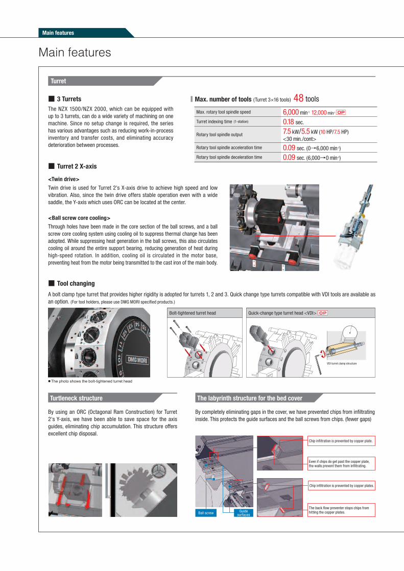
Turret
Main features
■ Max. number of tools (Turret 3×16 tools) 48 tools
Max. rotary tool spindle speed 6,000 min-1 12,000 min-1 OP
Turret indexing time (1-station) 0.18 sec.
Rotary tool spindle output 7.5 kW/5.5 kW (10 HP/7.5 HP)<30 min./cont>
Rotary tool spindle acceleration time 0.09 sec. (0→6,000 min-1)
Rotary tool spindle deceleration time 0.09 sec. (6,000→0 min-1)
Bolt-tightened turret head Quick-change type turret head <VDI>
● The photo shows the bolt-tightened turret head
The NZX 1500/NZX 2000, which can be equipped with up to 3 turrets, can do a wide variety of machining on one machine. Since no setup change is required, the series has various advantages such as reducing work-in-process inventory and transfer costs, and eliminating accuracy deterioration between processes.
A bolt clamp type turret that provides higher rigidity is adopted for turrets 1, 2 and 3. Quick change type turrets compatible with VDI tools are available as an option. (For tool holders, please use DMG MORI specified products.)
■ 3 Turrets
■ Tool changing
Ball screw Guide surfaces
Even if chips do get past the copper plate, the walls prevent them from infiltrating.
Chip infiltration is prevented by copper plate.
The back flow preventer stops chips from hitting the copper plates.
Chip infiltration is prevented by copper plates.
Turtleneck structure The labyrinth structure for the bed cover
By using an ORC (Octagonal Ram Construction) for Turret 2's Y-axis, we have been able to save space for the axis guides, eliminating chip accumulation. This structure offers excellent chip disposal.
By completely eliminating gaps in the cover, we have prevented chips from infiltrating inside. This protects the guide surfaces and the ball screws from chips. (fewer gaps)
Twin drive is used for Turret 2's X-axis drive to achieve high speed and low vibration. Also, since the twin drive offers stable operation even with a wide saddle, the Y-axis which uses ORC can be located at the center.
Through holes have been made in the core section of the ball screws, and a ball screw core cooling system using cooling oil to suppress thermal change has been adopted. While suppressing heat generation in the ball screws, this also circulates cooling oil around the entire support bearing, reducing generation of heat during high-speed rotation. In addition, cooling oil is circulated in the motor base, preventing heat from the motor being transmitted to the cast iron of the main body.
■ Turret 2 X-axis
<Ball screw core cooling>
<Twin drive>
Main features

Heat generationThermal displacement
The center stays the same
a b
NZX 1500/NZX 2000
Side cutter φ40 (φ1 1/2)
Y-axis travel +65 (+2.6)
Y-axis travel -45 (-1.8)
End mill φ20 (φ3/4)
Workpiece φ65 (φ2.6)
mm (in.)
a a
Grooving
Y-axis(-)
Y-axis(+)
X-axis(-) X-axis(+)X-axis(-) X-axis(+)
Spindle centerSpindle center
Y-axis(-)
Y-axis(+)
X-axis(-) X-axis(+)X-axis(-)
a
X-axis(+)
Spindle centerSpindle center
Contouring
Without Y-axis function With Y-axis function
1/10 or less 1/3 or less
Vibration
=
Heat generated by friction
Lubricating oil outflow
Lubricating oil
The lubricating oil in the oil pockets which were made by scraping is forced in and out through the gaps because of the contact pressure caused by vibration, generating heat.
Vibration is reduced by converting vibrational energy into heat energy. This helps control chattering caused by vibration.
Square guides' excellent damping characteristics
BMT: Built-in Motor Turret ORC: Octagonal Ram Construction
OptionOP
Y-axis control
Until now, slotting and contouring were done on turning centers by using polar coodinate interpolation, but the cutting conditions at the intersection point (a) of the workpiece center line and the machining line changed when the direction of travel on the X-axis was reversed. This affected the geometric accuracy. With the Y-axis control, however, the cutting conditions do not change, offering high geometric precision.
Key way slotting is possible with a φ40 mm (φ1 1/2 in.) side cutter
A φ20 mm (φ3/4 in.) end mill can cut right through the workpiece, without turning it over
■ Comparison between polar coordinate interpolation and Y-axis control
■ Bar machining with Y-axis control■ Key way milling using a turning center with the Y-axis function
Adjusting the key way width at the outside (a) and the inside (b) is difficult.
The key way width can be adjusted with the Y-axis function.
1. Side milling 2. Off-center keyway milling 3. Off-center drilling
Octagonal Ram Construction
The 4 guideways are located diagonally from each other, so they distort symmetrically in response to the heat generated by high-speed travel. This means that the center stays in the same position, offering high-speed, high-precision feed.
・Superior damping characteristics
・Controls thermal displacement
・ Achieves high-speed, high-
precision feed
■ Effects of ORC
The built-in structure, in which the motor is placed inside the turret, minimizes heat generation and vibration, improves transmission efficiency and significantly increases cutting power, speed and accuracy.
・Improved milling power・Improved milling accuracy
■ Effects of the BMT
■ Turret temperature increases ■ Vibration amplitudeCompared with conventional machine
Built-in Motor Turret
Original technology
Original technology
・Controls the turret’s heat and vibration・Reduced energy loss
Compared with conventional machine

Main features
X2
Y2
Z2
Z1
Y1
X1 X3
Y3
Z3
B
C1
C2
Turret 1Turret 3
Turret 2
X2
Y2
Z2
X1
Y1
Z1
B
C1
C2
Turret 1
Turret 2
Variations
Turret 1 Turret 2
NZX 1500|800SNZX 2000|800S
X1, Z1 X2, Z2
NZX 1500|800SYNZX 2000|800SY
X1, Z1, Y1 X2, Z2
NZX 1500|800SY2NZX 2000|800SY2
X1, Z1, Y1 X2, Z2, Y2
■ 2-turret specifications
Turret 1 Turret 2 Turret 3
NZX 1500|800STNZX 2000|800ST
X1, Z1 X2, Z2 X3, Z3
NZX 1500|800STY2NZX 2000|800STY2
X1, Z1, Y1 X2, Z2, Y2 X3, Z3
NZX 1500|800STY3NZX 2000|800STY3
X1, Z1, Y1 X2, Z2, Y2 X3, Z3, Y3
■ 3-turret specifications
■ Device to promptly and securely unload a workpiece■ The unloader can access both Spindle 1 and Spindle 2
Specifications Hand type Bucket type
Turning diameter φ10 mm (0.4 in.)-φ80 mm (3.1 in.)
Max. turning length 150 mm (5.9 in.)
Max. transfer weight 5.0 kg (11.0 lb.)
In-machine traveling type workpiece unloader OP In-machine traveling type workpiece unloader
Arm
Hand
Finished workpiece
Workpiece exit
Transfer conveyor
Finished workpiece
Workpiece bucket
Main features

High-precision equipment
OPCoolant cooling system (Separate type)
Raised coolant temperature causes thermal displacement in the fixtures and workpiece, affecting the machining accuracy of the workpiece. Use this unit to prevent the coolant from heating up. When using oil-based coolant, the coolant temperature can become extremely high even with the standard coolant pump, so please be sure to select this unit.
When using oil-based coolant, please be sure to consult with our sales representative.
● We cannot guarantee that this unit will completely control the coolant temperature. It is designed to help prevent oil temperature increases.
Cover
Machine rear
Covering the hydraulic unit prevents heat from being transmitted to the machine.
Hydraulic unit
Heat-shielding layout OPDirect scale feedback (X-axis, Z-axis)
● High accuracy, high resolution
● Greater accuracy than optical scale
● Highly resistant to condensation and oil
● Vibration and impact resistant characteristics
0.01 μm
The absolute magnetic linear scale (full
closed-loop control) made by Magnescale
is effective for high-precision positioning,
and is available as an option.
■ Resolution
OptionOPHigh precision

Cutting test
JIS: Japanese Industrial Standard ● The milling ability shown here is for C-axis brake specifications.
* 1045・1046(ANSI), C45・C45E・C45R(BS, DIN), 45(GB)
* 1045・1046(ANSI), C45・C45E・C45R(BS, DIN), 45(GB)
Material removal rate48.9 mL/min
(3.0 in3./min)<Spindle 1 / Turret 1>
ToolRotary tool spindle speed rangeCutting speedFeedrateDepth of cut
φ50 mm (φ2 in.) <4 teeth>955 min-1
150 m/min (492.2 fpm)764 mm/min (30.1 ipm)1.6 mm (0.06 in.)
Material removal rate19.2 mL/min(1.2 in3./min)<Spindle 1 / Turret 2>
ToolRotary tool spindle speed rangeCutting speedFeedrateDepth of cut
φ16 mm (φ5/8 in.)400 min-1
20 m/min (65.6 fpm)80 mm/min (3.1 ipm)15 mm (0.6 in.)
Material removal rate25.6 mL/min
(1.6 in3./min)<Spindle 2 / Turret 2>
ToolRotary tool spindle speed rangeCutting speedFeedrate
φ16 mm (φ5/8 in.)490 min-1
25 m/min (82.0 fpm)127 mm/min (5.0 ipm)
Tool M16×P2.0 <Spindle 2 / Turret 3>
Rotary tool spindle speed rangeCutting speed
200 min-1
10 m/min (32.8 fpm)
■ End mill
■ Heavy-duty cutting (O.D.)
■ Face mill
■ O.D. grooving
■ Drill ■ Tap
Material removal rate346.0 mL/min(21.1 in3./min)<Spindle 1 / Turret 1>
Spindle speedCutting speedFeedrateDepth of cut
822 min-1
160 m/min (525.0 fpm)0.4 mm/rev (0.016 ipr)5 mm (0.20 in.)
Width of cut 4.0 mm (0.16 in.)<Spindle 1 / Turret 1>
Spindle speedCutting speedFeedrateDepth of cut
403 min-1
100 m/min (328.1 fpm)0.1 mm/rev (0.004 ipr)5 mm (0.20 in.)
Turning
Milling
NZX 2000|800STY3
■ Material <JIS> S45C* (Carbon steel)
■ Material <JIS> S45C* (Carbon steel)
■ Throw-away drill
Spindle 1 Spindle 2
Material removal rate 360.0 mL/min (22.0 in3./min)
Turret Turret 1 Turret 2
Drill diameterSpindle speedCutting speedFeedrate
φ40 mm (φ1.6 in.)955 min-1
120 m/min (393.7 fpm)0.3 mm/rev (0.012 ipr)
φ40 mm (φ1.6 in.)955 min-1
120 m/min (393.7 fpm)0.3 mm/rev (0.012 ipr)
Material removal rate 360.0 mL/min (22.0 in3./min)
Turret Turret 2 Turret 3
Drill diameterSpindle speedCutting speedFeedrate
φ40 mm (φ1.6 in.)955 min-1
120 m/min (393.7 fpm)0.3 mm/rev (0.012 ipr)
φ40 mm (φ1.6 in.)955 min-1
120 m/min (393.7 fpm)0.3 mm/rev (0.012 ipr)
● The cutting test results indicated in this catalog are provided as an example. The results indicated in this catalog may not be obtained due to differences in cutting conditions and environmental conditions during measurement.
Machining ability

Peripheral equipment
*1 Please use a steel filter*2 Effective for ferrous alloysChip size guidelinesShort: chips shorter than 50 mm (2.0 in.), blocks of chips smaller than φ40 mm (φ1.6 in.)Long: bigger than the above.
● The options table shows the general options when using coolant. Changes may be necessary if you are not using coolant, or depending on the amount of coolant, compatibility with machines, or the specifications required.
● Please select a chip conveyor to suit the shape of your chips. When using special or difficult-to-cut material (chip hardness HRC45 or higher), please consult with our sales representative.
● We have prepared several options for different chip shapes and material. For details, please consult with our sales representative.
Discharge pressure MPa (psi) 7.0 (1,015)
Discharge volume L/min (gpm)50 Hz 48.6 (7.0)
60 Hz 48.6 (7.0)
The super-high pressure coolant unit generates a lot of heat because it discharges coolant at high pressure. The coolant cooling unit controls the temperature of the coolant and suppresses temperature increases in the workpiece, tools and table, ensuring stable machining accuracy. This is essential equipment when using super-high pressure coolant. A unit with a heater will be customized.
Recommended equipment
+ Coolant cooling system (Separate type)
Super-high pressure coolant system
This is ef fective for chip disposal, cooling the machining point and extending tool life.
Available Specifications
Workpiece material and chip size ○: Suitable ×: Not suitable
Steel Cast iron Aluminum, non-ferrous metal
Long Short Powdery Short Long Short Powdery
Hinge type+Drum filter type ○ ○ ○ ○ ○ ○ ○
Hinge type ○ × × × ○ × ×
Scraper type × ○ ○ ○ × × ×
Scraper type+Drum filter type Consultation is required × ○*1 ○ ○ × ○ ○
Magnet scraper type Consultation is required × ○ ○ ○ × × ×
Magnet scraper type+Drum filter type Consultation is required × ○*1 ○ ○ × ○*2 ○*2
Chip flow Chip bucket
External chip conveyor
Coolant cooling system (Separate type)
Headstock 2 sideSpindle 1 side
External chip conveyor
Super-high pressure coolant system (separate type)
Manual type in-machine tool presetter (Spindle 1 side/Headstock 2 side)
In-machine workpiece measurement system
Collet chuck
Mist collector
Coolant tank
Measurement of workpiece diameterMeasurement of workpiece length
OptionOPPeripheral equipment

CELOS
Uniform user interface with touch operation
From the idea to the finished productSimplifies every process from the idea to the finished product to facilitate operations.
▼ A wide variety of pre-installed applications ▼ 21.5" and 15.6" dual wide monitor
▼ New operating comfort with touch monitors
COMPATIBLE UNIFORM CONSISTENT
Compatible with PPS and ERP systems. Can be networked with CAD / CAM products. Open to trendsetting CELOS APP extensions.
Uniform, intuitive user interface for all high-tech machines from DMG MORI.
Consistent administration, documentation and visualisation of order, process and machine data.
21.5"ERGOline ® control panel with multi-touch monitor
Infinitely variable adjustment of the screen and the keyboard
SMARTkey®
Customised user authorisation. Individually adaptedaccess privileges to the control system and the machine.With internal USB memory
Keys for the selection of operating mode
Release button for machine functions in operating mode
MULTI-TOUCH-CONTROL PANELThe combination of advanced software and hardware enables excellent usability and distinctive functionality.
CELOS STATUS MONITORHere CELOS visualises the current condition of the machine regarding the process, provides important key figures about the current order and order progress and informs the operator with special icons and text messages about possible NC errors or imminent maintenance work
CELOS with 21.5” ERGOline Touch®
140807_CELOS_MC_Lathe_EA03V_CS6.indd 2 2014/08/09 13:08:42
CELOS APPs simplify fast and easy operation
CELOS –APP MENU: Central access to all available applications.CELOS supports the user in daily practice with a process-oriented menu structure. Thanks to the touch functionality of the user gets to the “APP MENU” with one single touch.
Similar to a smart phone or tablet terminal, the user has got direct access to all available APPs, which are differentiated according to their application field and can be selected with
a single touch via the “APP MENU”. For instance, CELOS APPs like the “JOB MANAGER“ or “JOB ASSISTANT“ support machine operators with the network-integrated preparation,
optimisation and systematic processing of production orders (with workpieces, fixture and NC programmes).
Systematic planning, administration and preparation of orders> Machine-related creation and configuration of new orders
> Structured saving of all production-related data and documents
> Visualisation of orders, including NC programme, equipment, etc.
WORKSHOP OF THE FUTUREWith its open structure and integration ability, CELOS offers unique opportunities for the
expansion of functionality with targeted applications.
CAD-CAM VIEW
Visualise workpieces and optimise programme data> Remotely control an online PC with CAD and CAM software installed
> Open CAD files on the machine to check 3D models or drawings
> Edit CAM files on the machine to regenerate NC programs
> Check machine motion in advance using CAM software with the simulation function
JOB ASSISTANT
Choosing and processing orders> Menu-guided set-up of the machine and processing of production orders
in the dialogue
> Reliable error prevention thanks to work instructions with binding check list
JOB MANAGER
140807_CELOS_MC_Lathe_EA03V_CS6.indd 3 2014/08/09 13:08:58

Machine specificationsItem NZX 1500|800S NZX 1500|800SY NZX 1500|800SY2
Capacity
Swing over bed mm (in.) 800 (31.5)
Swing over cross slide mm (in.) 800 (31.5)
Max. distance between spindle large noses mm (in.) 1,130 (44.4)
Max. turning diameter mm (in.) 320 (12.5) <Interference with the cover>
Standard turning diameter mm (in.) 200 (7.9)
Max. workpiece delivery diameter mm (in.) 300 (11.8)
Max. turning length mm (in.) 810 (31.8) <Max. length workpiece which can be machined using O.D. tool (with the workpiece supported at both ends)>
Bar work capacity mm (in.) 52 (2.0)
Travel
X-axis travel mm (in.) X1, X2: 210 (8.3)
Y-axis travel mm (in.) - Y1: 110 (4.3) <+65 (2.6), -45 (1.8)>
Y1: 110 (4.3) <+65 (2.6), -45 (1.8)>
Y2: 110 (4.3) <+45 (1.8), -65 (2.6)>
Z-axis travel mm (in.) Z1, Z2: 810 (31.9)
B-axis travel (Spindle 2) mm (in.) 900 (35.4)
Spindle 1
Max. spindle speed min-1 6,000
Number of spindle speed ranges Stage 2
Spindle nose JIS A2-5
Through-spindle hole diameter mm (in.) 61 (2.4)
Spindle bearing inner diameter mm (in.) 100 (3.9)
Min. spindle indexing increment 0.001̊
Spindle 2
Max. spindle speed min-1 6,000
Number of spindle speed ranges Stage 2
Spindle nose JIS A2-5
Through-spindle hole diameter mm (in.) 61 (2.4)
Spindle bearing inner diameter mm (in.) 100 (3.9)
Min. spindle indexing increment 0.001̊
Turret
Turret type 16-station×2
Number of tool stations 16×2=32
Shank height for square tool mm (in.) 20 (0.8)
Height of boring bar shank part mm (in.) 32 (1.3)
Turret indexing time (1-station) sec. 0.18
Max. rotary tool spindle speed min-1 6,000 [12,000]
Rotary tool machining ability mm (in.) Tap: M16, Drill: φ16 (φ0.6)
FeedrateRapid traverse rate mm/min (ipm) X1, X2: 30,000 (1,181.1)
Z1, Z2: 50,000 (1,968.5)
X1, X2: 30,000 (1,181.1)Y1: 20,000 (787.4)
Z1, Z2: 50,000 (1,968.5)
X1, X2: 30,000 (1,181.1)Y1, Y2: 20,000 (787.4)
Z1, Z2: 50,000 (1,968.5)
Jog feedrate mm/min (ipm) 0-5,000 (196.9)
Motors
Spindle 1 drive motor kW (HP) 22/18.5 (30/24.7) <30 min./cont> [25/22 (33.3/30) <30 min./cont> <High output>]
Spindle 2 drive motor kW (HP) 22/18.5 (30/24.7) <30 min./cont> [25/22 (33.3/30) <30 min./cont> <High output>]
Rotary tool spindle drive motor <30 min./cont> kW (HP) 7.5/5.5 (10/7.5)
Feed motor kW (HP)X1: 3.0 (4.0)
X2: 1.2 (1.6)×2Z1, Z2: 4.0 (5.3)
X1: 3.0 (4.0), X2: 1.2 (1.6)×2Y1: 4.0 (5.3)
Z1, Z2: 4.0 (5.3)
X1: 3.0 (4.0), X2: 2.5 (3.3)×2Y1: 4.0 (5.3), Y2: 2.5 (3.3)
Z1, Z2: 4.0 (5.3)
Hydraulic pump motor kW (HP) 1.5 (2.0) or equivalent
Lubricanting oil pump motor kW (HP) 0.017 (0.02)
Coolant pump motor kW (HP) 0.325/0.520 (0.43/0.69)
Cooling oil motor <50/60 Hz> kW (HP) 4.2/4.7 (5.6/6.2)
Power sources(Standard)
Electrical power supply <cont> kVA 75.6 79.1 83.5
Compressed air supply MPa, L/min (psi/gpm) 0.5, 200 (72.5, 52.8) <ANR>
Tank capacity
Hydraulic oil tank capacity L (gal.) 10 (2.6)
Lubricanting oil tank capacity L (gal.) 4.2 (1.1)
Coolant tank capacity L (gal.) 450 (118.8)
Oil cooler tank capacity L (gal.) 52 (13.7)
Machine sizeMachine height <From floor> mm (in.) 2,320 (91.3)
Floor space <Width×Depth> mm (in.) 4,255 (167.5) <Machine: 3,730 (146.9)+Tank: 525 (20.7)> [Chip conveyor right disposal: +806 (31.7)]×2,835 (111.6)
Mass of machine kg (Ib.) 8,100 (17,820) 8,200 (18,040) 8,400 (18,480)NZX 1500_2000 (140807)[ ] Option
● Bar work capacity: Depending on the chuck cylinder used and its restrictions, it may not be possible to reach full bar work capacity.● Max. spindle speed: Depending on restrictions imposed by the workpiece clamping device, fixture and tool used, it may not be possible to rotate at the maximum spindle speed.● ANR: Refers to a standard atmospheric state; i. e., temperature at 20 C゚ (68 F゚); absolute pressure at 101.3 kPa (14.7 psi); and relative humidity at 65%.● Power sources, Machine size: The actual values may differ from those specified in the catalogue, depending on the optional features and peripheral equipment.● Compressed air supply: Please be sure to supply clean compressed air <air pressure: 0.7 MPa (101.5 psi), pressure dew point: 10℃ (50°F) or below>. ● A criterion capacity to select a compressor is 90 L/min (23.8 gpm) per 0.75 kW (1 HP). However, this figure may differ depending on the type of compressors and options attached.
For details, please check the compressor specifications.● When the tool tip air blow is regularly used, air supply of more than 300 L/min (79.2 gpm) is separately required.● The information in this catalog is valid as of August 2014.● JIS: Japanese Industrial Standard
Specifications

NZX 1500_2000 (140807)
Item NZX 1500|800ST NZX 1500|800STY2 NZX 1500|800STY3
Capacity
Swing over bed mm (in.) 800 (31.5)
Swing over cross slide mm (in.) 800 (31.5)
Max. distance between spindle large noses mm (in.) 1,130 (44.4)
Max. turning diameter mm (in.) 320 (12.5) <Interference with the cover>
Standard turning diameter mm (in.) 200 (7.9)
Max. workpiece delivery diameter mm (in.) 300 (11.8)
Max. turning length mm (in.) 810 (31.8) <Max. length workpiece which can be machined using O.D. tool on Turret 2 (with the workpiece supported at both ends)>
Bar work capacity mm (in.) 52 (2.0)
Travel
X-axis travel mm (in.) X1, X2, X3: 210 (8.3)
Y-axis travel mm (in.) - Y1: 110 (4.3) <+65 (2.6), -45 (1.8)>Y2: 110 (4.3) <+45 (1.8), -65 (2.6)>
Y1, Y3: 110 (4.3) <+65 (2.6), -45 (1.8)>Y2: 110 (4.3) <+45 (1.8), -65 (2.6)>
Z-axis travel mm (in.) Z1, Z3: 300 (11.8) <+100*(3.9)>, Z2: 810 (31.9)
B-axis travel (Spindle 2) mm (in.) 900 (35.4)
Spindle 1
Max. spindle speed min-1 6,000
Number of spindle speed ranges Stage 2
Spindle nose JIS A2-5
Through-spindle hole diameter mm (in.) 61 (2.4)
Spindle bearing inner diameter mm (in.) 100 (3.9)
Min. spindle indexing increment 0.001̊
Spindle 2
Max. spindle speed min-1 6,000
Number of spindle speed ranges Stage 2
Spindle nose JIS A2-5
Through-spindle hole diameter mm (in.) 61 (2.4)
Spindle bearing inner diameter mm (in.) 100 (3.9)
Min. spindle indexing increment 0.001̊
Turret
Turret type 16-station×3
Number of tool stations 16×3=48
Shank height for square tool mm (in.) 20 (0.8)
Height of boring bar shank part mm (in.) 32 (1.3)
Turret indexing time (1-station) sec. 0.18
Max. rotary tool spindle speed min-1 6,000 [12,000]
Rotary tool machining ability mm (in.) Tap: M16, Drill: φ16 (φ0.6)
FeedrateRapid traverse rate mm/min (ipm) X1, X2, X3: 30,000 (1,181.1)
Z1, Z2, Z3: 50,000 (1,968.5)
X1, X2, X3: 30,000 (1,181.1)Y1, Y2: 20,000 (787.4)
Z1, Z2, Z3: 50,000 (1,968.5)
X1, X2, X3: 30,000 (1,181.1)Y1, Y2, Y3: 20,000 (787.4)
Z1, Z2, Z3: 50,000 (1,968.5)
Jog feedrate mm/min (ipm) 0-5,000 (196.9)
Motors
Spindle 1 drive motor kW (HP) 22/18.5 (30/24.7) <30 min./cont> [25/22 (33.3/30) <30 min./cont> <High output>]
Spindle 2 drive motor kW (HP) 22/18.5 (30/24.7) <30 min./cont> [25/22 (33.3/30) <30 min./cont> <High output>]
Rotary tool spindle drive motor <30 min./cont> kW (HP) 7.5/5.5 (10/7.5)
Feed motor kW (HP)X1, X3: 3.0 (4.0)X2: 1.2 (1.6)×2
Z1, Z2, Z3: 4.0 (5.3)
X1, X3: 3.0 (4.0), X2: 2.5 (3.3)×2Y1: 4.0 (5.3), Y2: 2.5 (3.3)
Z1, Z2, Z3: 4.0 (5.3)
X1, X3: 3.0 (4.0), X2: 2.5 (3.3)×2Y1, Y3: 4.0 (5.3), Y2: 2.5 (3.3)
Z1, Z2, Z3: 4.0 (5.3)
Hydraulic pump motor kW (HP) 1.5 (2.0) or equivalent
Lubricanting oil pump motor kW (HP) 0.017 (0.02)
Coolant pump motor kW (HP) 0.325/0.520 (0.43/0.69)
Cooling oil motor <50/60 Hz> kW (HP) 4.2/4.7 (5.6/6.2)
Power sources(Standard)
Electrical power supply <cont> kVA 82.4 86.7 90.2
Compressed air supply MPa, L/min (psi/gpm) 0.5, 200 (72.5, 52.8) <ANR>
Tank capacity
Hydraulic oil tank capacity L (gal.) 10 (2.6)
Lubricanting oil tank capacity L (gal.) 4.2 (1.1)
Coolant tank capacity L (gal.) 450 (118.8)
Oil cooler tank capacity L (gal.) 52 (13.7)
Machine sizeMachine height <From floor> mm (in.) 2,320 (91.3)
Floor space <Width×Depth> mm (in.) 4,255 (167.5) <Machine: 3,730 (146.9)+Tank: 525 (20.7)> [Chip conveyor right disposal: +806 (31.7)]×2,835 (111.6)
Mass of machine kg (Ib.) 9,000 (19,800) 9,300 (20,460) 9,400 (20,680)
[ ] Option● Bar work capacity: Depending on the chuck cylinder used and its restrictions, it may not be possible to reach full bar work capacity.● Max. spindle speed: Depending on restrictions imposed by the workpiece clamping device, fixture and tool used, it may not be possible to rotate at the maximum spindle speed.● ANR: Refers to a standard atmospheric state; i. e., temperature at 20 C゚ (68 F゚); absolute pressure at 101.3 kPa (14.7 psi); and relative humidity at 65%.● Power sources, Machine size: The actual values may differ from those specified in the catalogue, depending on the optional features and peripheral equipment.● Compressed air supply: Please be sure to supply clean compressed air <air pressure: 0.7 MPa (101.5 psi), pressure dew point: 10℃ (50°F) or below>.● A criterion capacity to select a compressor is 90 L/min (23.8 gpm) per 0.75 kW (1 HP). However, this figure may differ depending on the type of compressors and options attached.
For details, please check the compressor specifications.● When the tool tip air blow is regularly used, air supply of more than 300 L/min (79.2 gpm) is separately required.*When one turret is moving in the plus direction, another turret moves in the minus direction.● The information in this catalog is valid as of August 2014.● JIS: Japanese Industrial Standard

Item NZX 2000|800S NZX 2000|800SY NZX 2000|800SY2
Capacity
Swing over bed mm (in.) 800 (31.5)
Swing over cross slide mm (in.) 800 (31.5)
Max. distance between spindle large noses mm (in.) 1,130 (44.4)
Max. turning diameter mm (in.) 320 (12.5) <Interference with the cover>
Standard turning diameter mm (in.) 200 (7.9)
Max. workpiece delivery diameter mm (in.) 300 (11.8)
Max. turning length mm (in.) 810 (31.8) <Max. length workpiece which can be machined using O.D. tool (with the workpiece supported at both ends)>
Bar work capacity mm (in.) 65 (2.5)
Travel
X-axis travel mm (in.) X1, X2: 210 (8.3)
Y-axis travel mm (in.) - Y1: 110 (4.3) <+65 (2.6), -45 (1.8)>
Y1: 110 (4.3) <+65 (2.6), -45 (1.8)>
Y2: 110 (4.3) <+45 (1.8), -65 (2.6)>
Z-axis travel mm (in.) Z1, Z2: 810 (31.9)
B-axis travel (Spindle 2) mm (in.) 870 (34.3)
Spindle 1
Max. spindle speed min-1 5,000
Number of spindle speed ranges Stage 2
Spindle nose JIS A2-6
Through-spindle hole diameter mm (in.) 73 (2.9)
Spindle bearing inner diameter mm (in.) 120 (4.7)
Min. spindle indexing increment 0.001̊
Spindle 2
Max. spindle speed min-1 5,000
Number of spindle speed ranges Stage 2
Spindle nose JIS A2-6
Through-spindle hole diameter mm (in.) 73 (2.9)
Spindle bearing inner diameter mm (in.) 120 (4.7)
Min. spindle indexing increment 0.001̊
Turret
Turret type 16-station×2
Number of tool stations 16×2=32
Shank height for square tool mm (in.) 20 (0.8)
Height of boring bar shank part mm (in.) 32 (1.3)
Turret indexing time (1-station) sec. 0.18
Max. rotary tool spindle speed min-1 6,000 [12,000]
Rotary tool machining ability mm (in.) Tap: M16, Drill: φ16 (φ0.6)
FeedrateRapid traverse rate mm/min (ipm) X1, X2: 30,000 (1,181.1)
Z1, Z2: 50,000 (1,968.5)
X1, X2: 30,000 (1,181.1)Y1: 20,000 (787.4)
Z1, Z2: 50,000 (1,968.5)
X1, X2: 30,000 (1,181.1)Y1, Y2: 20,000 (787.4)
Z1, Z2: 50,000 (1,968.5)
Jog feedrate mm/min (ipm) 0-5,000 (196.9)
Motors
Spindle 1 drive motor <30 min./cont> kW (HP) 25/22 (33.3/30) [25/22 (33.3/30) <High-torque>]
Spindle 2 drive motor <30 min./cont> kW (HP) 25/22 (33.3/30) [25/22 (33.3/30) <High-torque>]
Rotary tool spindle drive motor <30 min./cont> kW (HP) 7.5/5.5 (10/7.5)
Feed motor kW (HP)X1: 3.0 (4.0)
X2: 1.2 (1.6)×2Z1, Z2: 4.0 (5.3)
X1: 3.0 (4.0), X2: 1.2 (1.6)×2Y1: 4.0 (5.3)
Z1, Z2: 4.0 (5.3)
X1: 3.0 (4.0) X2: 2.5 (3.3)×2Y1: 4.0 (5.3), Y2: 2.5 (3.3)
Z1, Z2: 4.0 (5.3)
Hydraulic pump motor kW (HP) 1.5 (2.0) or equivalent
Lubricanting oil pump motor kW (HP) 0.017 (0.02)
Coolant pump motor kW (HP) 0.325/0.520 (0.43/0.69)
Cooling oil motor <50/60 Hz> kW (HP) 4.2/4.7 (5.6/6.2)
Power sources(Standard)
Electrical power supply <cont> kVA 83.7 87.1 91.5
Compressed air supply MPa, L/min (psi/gpm) 0.5, 200 (72.5, 52.8) <ANR>
Tank capacity
Hydraulic oil tank capacity L (gal.) 10 (2.6)
Lubricanting oil tank capacity L (gal.) 4.2 (1.1)
Coolant tank capacity L (gal.) 450 (118.8)
Oil cooler tank capacity L (gal.) 52 (13.7)
Machine sizeMachine height <From floor> mm (in.) 2,320 (91.3)
Floor space <Width×Depth> mm (in.) 4,255 (167.5) <Machine: 3,730 (146.9)+Tank: 525 (20.7)> [Chip conveyor right disposal: +806 (31.7)]×2,835 (111.6)
Mass of machine kg (Ib.) 8,300 (18,260) 8,400 (18,480) 8,600 (18,920)
Noise data A-weighted, time-average radiated sound pressure level dB 61-68 <measurement uncertainty is 4 dB>
[ ] Option● Bar work capacity: Depending on the chuck cylinder used and its restrictions, it may not be possible to reach full bar work capacity.● Max. spindle speed: Depending on restrictions imposed by the workpiece clamping device, fixture and tool used, it may not be possible to rotate at the maximum spindle speed.● ANR:Refers to a standard atmospheric state; i. e., temperature at 20 C゚ (68 F゚); absolute pressure at 101.3 kPa (14.7 psi); and relative humidity at 65%.● Power sources, Machine size: The actual values may differ from those specified in the catalogue, depending on the optional features and peripheral equipment.● Compressed air supply: Please be sure to supply clean compressed air <air pressure: 0.7 MPa (101.5 psi), pressure dew point: 10℃ (50°F) or below>.● A criterion capacity to select a compressor is 90 L/min (23.8 gpm) per 0.75 kW (1 HP). However, this figure may differ depending on the type of compressors and options attached.
For details, please check the compressor specifications.● When the tool tip air blow is regularly used, air supply of more than 300 L/min (79.2 gpm) is separately required.● Noise data: the measurement was performed at the front of the NZX 2000 |800STY3 machine with a maximum spindle speed of 5,000 min-1.
For details, please consult with our sales representative.● The information in this catalog is valid as of August 2014.● JIS: Japanese Industrial Standard
NZX 1500_2000 (140807)
Machine specifications
Specifications

Item NZX 2000|800ST NZX 2000|800STY2 NZX 2000|800STY3
Capacity
Swing over bed mm (in.) 800 (31.5)
Swing over cross slide mm (in.) 800 (31.5)
Max. distance between spindle large noses mm (in.) 1,130 (44.4)
Max. turning diameter mm (in.) 320 (12.5) <Interference with the cover>
Standard turning diameter mm (in.) 200 (7.9)
Max. workpiece delivery diameter mm (in.) 300 (11.8)
Max. turning length mm (in.) 810 (31.8) (Max. length workpiece which can be machined using O.D. tool on Turret 2 <with the workpiece supported at both ends>)
Bar work capacity mm (in.) 65 (2.5)
Travel
X-axis travel mm (in.) X1, X2, X3: 210 (8.3)
Y-axis travel mm (in.) - Y1: 110 (4.3) <+65 (2.6), -45 (1.8)>Y2: 110 (4.3) <+45 (1.8), -65 (2.6)>
Y1, Y3: 110 (4.3) <+65 (2.6), -45 (1.8)>Y2: 110 (4.3) <+45 (1.8), -65 (2.6)>
Z-axis travel mm (in.) Z1, Z3: 300 (11.8) <+100*(3.9)>, Z2: 810 (31.9)
B-axis travel (Spindle 2) mm (in.) 870 (34.3)
Spindle 1
Max. spindle speed min-1 5,000
Number of spindle speed ranges Stage 2
Spindle nose JIS A2-6
Through-spindle hole diameter mm (in.) 73 (2.9)
Spindle bearing inner diameter mm (in.) 120 (4.7)
Min. spindle indexing increment 0.001̊
Spindle 2
Max. spindle speed min-1 5,000
Number of spindle speed ranges Stage 2
Spindle nose JIS A2-6
Through-spindle hole diameter mm (in.) 73 (2.9)
Spindle bearing inner diameter mm (in.) 120 (4.7)
Min. spindle indexing increment 0.001̊
Turret
Turret type 16-station×3
Number of tool stations 16×3=48
Shank height for square tool mm (in.) 20 (0.8)
Height of boring bar shank part mm (in.) 32 (1.3)
Turret indexing time (1-station) sec. 0.18
Max. rotary tool spindle speed min-1 6,000 [12,000]
Rotary tool machining ability mm (in.) Tap: M16, Drill: φ16 (φ0.6)
FeedrateRapid traverse rate mm/min (ipm) X1, X2, X3: 30,000 (1,181.1)
Z1, Z2, Z3: 50,000 (1,968.5)
X1, X2, X3: 30,000 (1,181.1)Y1, Y2: 20,000 (787.4)
Z1, Z2, Z3: 50,000 (1,968.5)
X1, X2, X3: 30,000 (1,181.1)Y1, Y2, Y3: 20,000 (787.4)
Z1, Z2, Z3: 50,000 (1,968.5)
Jog feedrate mm/min (ipm) 0-5,000 (196.9)
Motors
Spindle 1 drive motor <30 min./cont> kW (HP) 25/22 (33.3/30) [25/22 (33.3/30) <High-torque>]
Spindle 2 drive motor <30 min./cont> kW (HP) 25/22 (33.3/30) [25/22 (33.3/30) <High-torque>]
Rotary tool spindle drive motor <30 min./cont> kW (HP) 7.5/5.5 (10/7.5)
Feed motor kW (HP)X1, X3: 3.0 (4.0)X2: 1.2 (1.6)×2
Z1, Z2, Z3: 4.0 (5.3)
X1, X3: 3.0 (4.0), X2: 2.5 (3.3)×2Y1: 4.0 (5.3), Y2: 2.5 (3.3)
Z1, Z2, Z3: 4.0 (5.3)
X1, X3: 3.0 (4.0), X2: 2.5 (3.3)×2Y1, Y3: 4.0 (5.3), Y2: 2.5 (3.3)
Z1, Z2, Z3: 4.0 (5.3)
Hydraulic pump motor kW (HP) 1.5 (2.0) or equivalent
Lubricanting oil pump motor kW (HP) 0.017 (0.02)
Coolant pump motor kW (HP) 0.325/0.520 (0.43/0.69)
Cooling oil motor <50/60 Hz> kW (HP) 4.2/4.7 (5.6/6.2)
Power sources(Standard)
Electrical power supply <cont> kVA 90.4 94.8 98.2
Compressed air supply MPa, L/min (psi/gpm) 0.5, 200 (72.5, 52.8) <ANR>
Tank capacity
Hydraulic oil tank capacity L (gal.) 10 (2.6)
Lubricanting oil tank capacity L (gal.) 4.2 (1.1)
Coolant tank capacity L (gal.) 450 (118.8)
Oil cooler tank capacity L (gal.) 52 (13.7)
Machine sizeMachine height <From floor> mm (in.) 2,320 (91.3)
Floor space <Width×Depth> mm (in.) 4,255 (167.5) <Machine: 3,730 (146.9)+Tank: 525 (20.7)> [Chip conveyor right disposal: +806 (31.7)]×2,835 (111.6)
Mass of machine kg (Ib.) 9,200 (20,240) 9,500 (20,900) 9,600 (21,120)
Noise data A-weighted, time-average radiated sound pressure level dB 61-68 <measurement uncertainty is 4 dB>
[ ] Option● Bar work capacity: Depending on the chuck cylinder used and its restrictions, it may not be possible to reach full bar work capacity.● Max. spindle speed: Depending on restrictions imposed by the workpiece clamping device, fixture and tool used, it may not be possible to rotate at the maximum spindle speed.● ANR: Refers to a standard atmospheric state; i. e., temperature at 20 C゚ (68 F゚); absolute pressure at 101.3 kPa (14.7 psi); and relative humidity at 65%.● Power sources, Machine size: The actual values may differ from those specified in the catalogue, depending on the optional features and peripheral equipment.● Compressed air supply: Please be sure to supply clean compressed air <air pressure: 0.7 MPa (101.5 psi), pressure dew point: 10℃ (50°F) or below>.● A criterion capacity to select a compressor is 90 L/min (23.8 gpm) per 0.75 kW (1 HP). However, this figure may differ depending on the type of compressors and options attached.
For details, please check the compressor specifications.● When the tool tip air blow is regularly used, air supply of more than 300 L/min (79.2 gpm) is separately required.*When one turret is moving in the plus direction, another turret moves in the minus direction.● Noise data: the measurement was performed at the front of the NZX 2000 |800STY3 machine with a maximum spindle speed of 5,000 min-1.
For details, please consult with our sales representative.● The information in this catalog is valid as of August 2014.● JIS: Japanese Industrial Standard
NZX 1500_2000 (140807)

EXPORTATION: All contracts are subject to export permit by the Government of Japan. Customer shall comply with the laws and regulations of the exporting country governing the exportation or re-exportation of the Equipment, including but not limited to the Export Administration Regulations. The Equipment is subject to export restrictions imposed by Japan and other exporting countries and the Customer will not export or permit the export of the Equipment anywhere outside the exporting country without proper government authorization. To prevent the illegal diversion of the Equipment to individuals or nations that threaten international security, it may include a “Relocation Machine Security Function” that automatically disables the Equipment if it is moved following installation. If the Equipment is so-disabled, it can only be re-enabled by contacting DMG MORI SEIKI or its distributor representative. DMG MORI SEIKI and its distributor representative may refuse to re-enable the Equipment if it determines that doing so would be an unauthorized export of technology or otherwise violates applicable export restrictions. DMG MORI SEIKI and its distributor representative shall have no obligation to re-enable such Equipment. DMG MORI SEIKI and its distributor representative shall have no liability (including for lost profits or business interruption or under the limited service warranty included herein) as a result of the Equipment being disabled.
<Precautions for Machine Relocation>
Nagoya Head Office □ 2-35-16 Meieki, Nakamura-ku, Nagoya City, Aichi 450-0002, Japan Phone: +81-52-587-1811
Nara Campus Nara No. 1 Plant □ 362 Idono-cho, Yamato-Koriyama City, Nara 639-1183, Japan Phone: +81-743-53-1121 Nara No. 2 Plant □ 106 Kita-Koriyama-cho, Yamato-Koriyama City, Nara 639-1160, Japan Phone: +81-743-53-1125Iga Campus □ 201 Midai, Iga City, Mie 519-1414, Japan Phone: +81-595-45-4151Chiba Campus □ 488-19 Suzumi-cho, Funabashi City, Chiba 274-0052, Japan Phone: +81-47-410-8800
DMG MORI SEIKI CO., LTD.
● DCG, DDM, BMT and ORC are trademarks or registered trademarks of DMG MORI SEIKI CO., LTD. in Japan, the USA and other countries.● If you have any questions regarding the content, contact our sales representative.● The information in this catalog is valid as of August 2014. Designs and specifications are subject to changes without notice.● The machines shown in the catalog may differ from the actual machines. The location and the size of the nameplates may also differ from the actual machines, or the nameplates may not be
attached to some machines.● DMG MORI SEIKI is not responsible for differences between the information in the catalog and the actual machine.
2-year warranty, twice the peace of mind. For machines delivered outside of Japan, parts relating to machine breakdown will be guaranteed free for 2 years from the date of installation, and labor costs to repair will be free for 1 year. Please contact our sales representative for details.
NZX1520ND-EA01V
V.1408.CDT.0000
Created in Japan