· homer tyco/pu siemens/furnas ge culter-hammer schneider/square d. honeywell xmc0 3100 42/45...
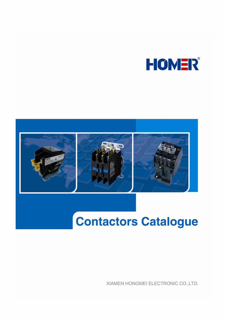
TRANSCRIPT
- -

- -
- -
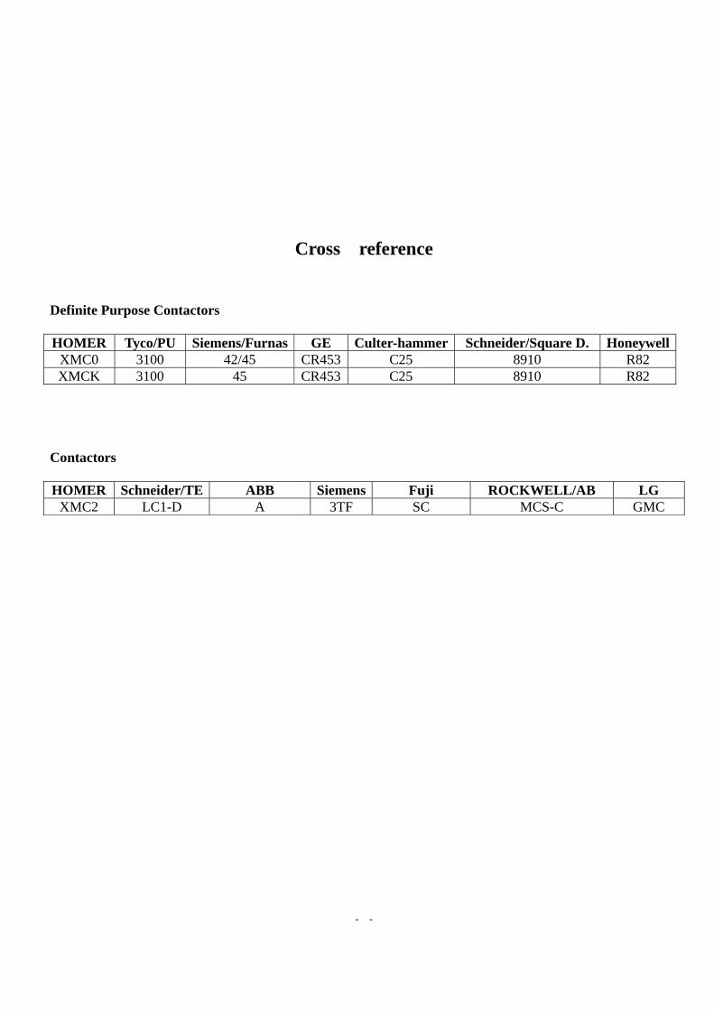
Cross reference
Definite Purpose Contactors HOMER Tyco/PU Siemens/Furnas GE Culter-hammer Schneider/Square D. Honeywell
XMC0 3100 42/45 CR453 C25 8910 R82 XMCK 3100 45 CR453 C25 8910 R82
Contactors HOMER Schneider/TE ABB Siemens Fuji ROCKWELL/AB LG
XMC2 LC1-D A 3TF SC MCS-C GMC

- -

- - - 1 -
XMC0 Series Definite Purpose Contactors
Description
HOMER XMC0 series high performance definite purpose contactors (1-pole, 1-pole+shunt, 2-pole, 3-pole(optional Auxiliary Contact Blocks or Microswitch Blocks available), 3-pole+1NC and 3-pole+1NO, from 12A to 90A ) are ideal for(HVAC)air conditioning, refrigeration, heating, data processing, welding, elevators, hoists & cranes, washing machine, lighting, pools & spas and food service equipments. XMC0 series definite purpose contactors meet UL508 standard.
Features
1. Unique structure of amortization system eliminates contact bounce. 2. Tools-free accessories make quick & easy snap on. 3. Various terminal optional for specific application. 4. Easy coil change. 5. Universal mounting plate allows an easy replacing to other brands. 6. Heavy duty Silver Metal Oxide composition contacts with longer electrical endurance. 7. Coils are Class F (155 ) temperature insulated with wide range of voltage℃ s and 50/60Hz ratings. 8. Double “E” shaped Magnet Assembly provides optimal performance with lower power consumption. 9. Effective dustproof structure. 10. UL and CCC approved, some models SEMKO, KETI or TÜV plus.
Type model nomenclature - Ordering Information
XM C 0 – 25 3 . E B B C 30 F Q □ □ □ 1 2 3 4 5 6 7 8 9 10 11 12 13 14 15
Number digit 1: Manufacturer’s code
XM – Xiamen Hongmei Electronic Co., Ltd.
Number digit 2: Product Type
C – Contactor
Number digit 3: Design Sequence Number – 0
- - - 2 -
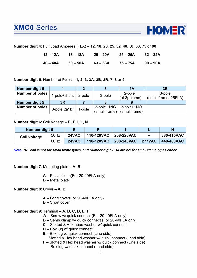
Number digit 4: Full Load Amperes (FLA) – 12, 18, 20, 25, 32, 40, 50, 63, 75 or 90
12 – 12A 18 – 18A 20 – 20A 25 – 25A 32 – 32A
40 – 40A 50 – 50A 63 – 63A 75 – 75A 90 – 90A
Number digit 5: Number of Poles – 1, 2, 3, 3A, 3B, 3R, 7, 8 or 9
Number digit 5 1 2 3 3A 3B Number of poles 1-pole+shunt 2-pole 3-pole 2-pole
(at 3p frame) 3-pole
(small frame, 25FLA)Number digit 5 3R 7 8 9 Number of poles 3-pole(2a1b) 1-pole 3-pole+1NC
(small frame)3-pole+1NO (small frame)
Number digit 6: Coil Voltage – E, F, I, L, N
Number digit 6 E F I L N 50Hz 24VAC 110-120VAC 208-220VAC -- 380-415VACCoil voltage 60Hz 24VAC 110-120VAC 208-240VAC 277VAC 440-480VAC
Note: “N” coil is not for small frame types, and Number digit 7~14 are not for small frame types either.
Number digit 7: Mounting plate – A, B
A – Plastic base(For 20-40FLA only) B – Metal plate
Number digit 8: Cover – A, B
A – Long cover(For 20-40FLA only) B – Short cover
Number digit 9: Terminal – A, B, C, D, E, F
A – Screw w/ quick connect (For 20-40FLA only) B – Sems clamp w/ quick connect (For 20-40FLA only) C – Slotted & Hex head washer w/ quick connect D – Box lug w/ quick connect E – Box lug w/ quick connect (Line side)
Slotted & Hex head washer w/ quick connect (Load side) F – Slotted & Hex head washer w/ quick connect (Line side)
Box lug w/ quick connect (Load side)

- - - 3 -
Number digit 10: Auxiliary Contact Blocks or Microswitch Blocks (for 3-pole) (Left & Right) side (SPDT is Microswitch) – 0, 1, 3, 4, 5, 6, 1P, 3P, 4P, 5P, 6P, L, L1, L2, R, R1, R2
Auxiliary Contact Blocks or Microswitch Blocks at Left Side
Auxiliary Contact Blocks or Microswitch Blocks at Right Side
0 – None (Standard type) 1 – 1NC+1NO, pressure plate screws w/ quick connect 1P – 1NC+1NO, pressure plate screws3 – 1NC, pressure plate screws w/ quick connect 3P – 1NC, pressure plate screws 4 – 1NO, pressure plate screws w/ quick connect 4P – 1NO, pressure plate screws 5 – 2NC, pressure plate screws w/ quick connect 5P – 2NC, pressure plate screws 6 – 2NO, pressure plate screws w/ quick connect 6P – 2NO, pressure plate screws L – Left 2 SPDT R – Right 2 SPDT L1 – Left SPDT(position 1) R1 – Right SPDT(position 1) L2 – Left SPDT(position 2) R2 – Right SPDT(position 2) For example: 4P – 1NC pressure plate screws w/ quick connect at left and 1NO pressure plate screws at right56 – 2NC pressure plate screws w/ quick connect at left and 2NO pressure plate screws
w/ quick connect at right LR1 – Left 2 SPDT, Right SPDT(position 1) 3R2 – Left 1NC Pressure Plate screws w/ quick connect, Right SPDT(position 2)
Note: If “00” will be the final digit(s) in selection, omit from model nomenclature.
Number digit 11: Coil terminals – Blank, F
Blank – Dual terminals without screws in 1-and 2- pole models and Single terminals with screws in 3-pole models
F – Dual terminals with screws in 3- pole models Number digit 12: Power quick terminals – Blank, G, Q
Blank – Quad terminals in 1-and 2- pole models and Dual terminals in 3-pole models
G – Without any terminals Q – Dual terminals at the side near coil terminal and Quad terminals at the other
side in 3-pole 20-40FLA models Number digit 13: Nameplate – Blank, T
Blank – Nameplate shows actual product rating T – Nameplate shows derated product rating
Number digit 14: Contact construction style (for 50/63 FLA) – Blank, Z
Blank – Flat construction in shape Z – Bend construction in shape (new design)
Number digit 15: Option
Customer assigned suffix “X” where “X” may be any alphanumeric character or any combined alphanumeric character.

- 4 -
Characteristics
Conforming to standard IEC60947-4-1, GB14048.4, EN60947-4-1, UL508
Approvals UL(USR/CNR) and CCC Some models SEMKO, KETI or TÜV plus
Protective treatment Total climate tropical use “TH”
Operating position Vertical (Metal/Plastic base mounting)
operation ℃ -25℃~+70℃ Ambient temperature storage ℃ -40℃~+70℃ Relative humidity 90-95%RH at 40℃ Pollution degree 3
contactor open g 6 Shock resistance 1/2 sine wave=11 ms contactor closed g 15
contactor open g 2 Vibration resistance 5 to 300 Hz contactor closed g 4
Performance
XMC0- Poles 1 2 3 3A 3B 7 8 9 Rated insulation voltage V 690 Rated operating voltage V 240/277,480,600 (60Hz) or 230,400 (50Hz)Full load ampere(FLA) A 12 18 25 32 40 50 63 75 90Resistive Amps Rating(RES) A 20 25 35 40 50 63 75 94 120Making capacity(230V cosφ0.45) A 12×FLA Breaking capacity(230V cosφ0.45) A 10×FLA Switching frequency op/h 360 Electrical endurance(ARI 780/790) cycle 200,000 Mechanical endurance(ARI 780/790) cycle 500,000
- 5 -
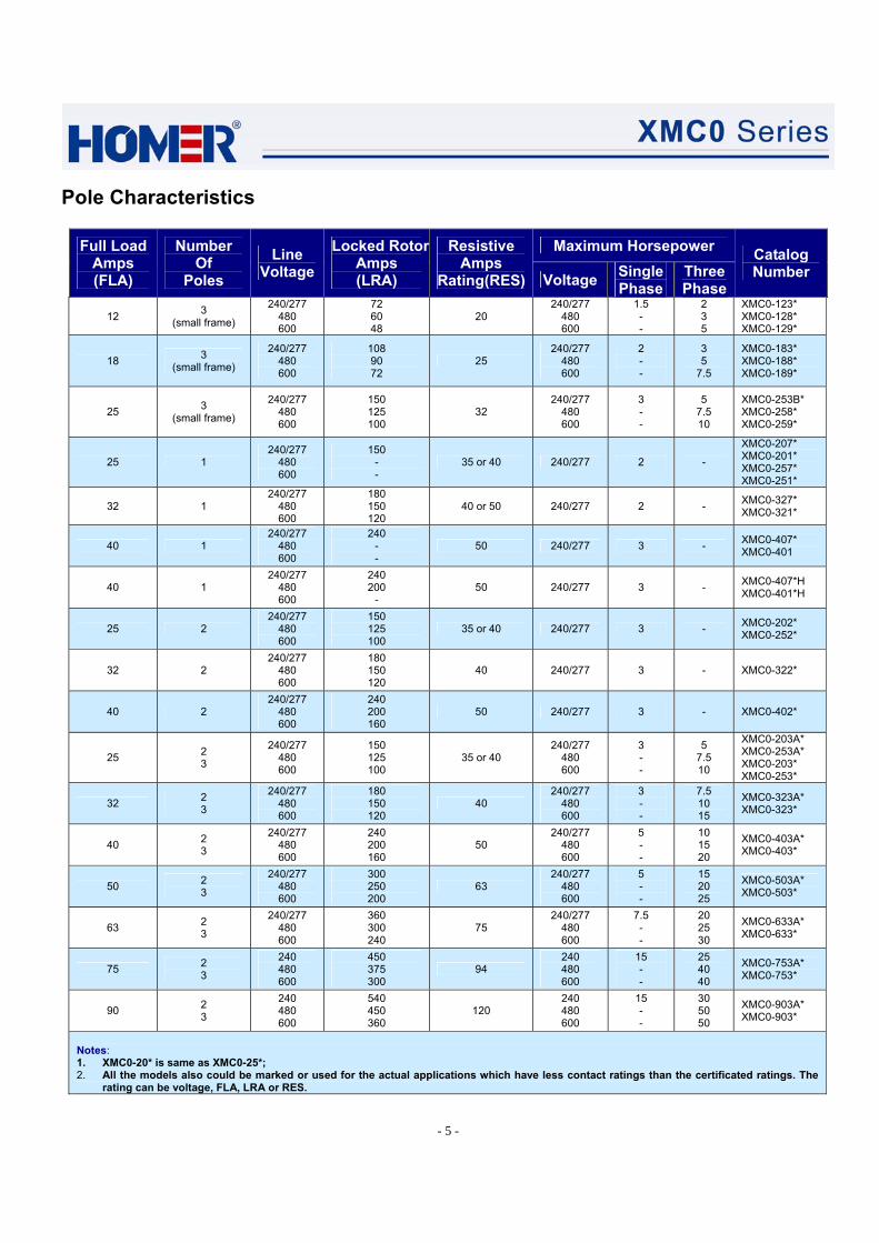
Pole Characteristics
Maximum Horsepower Full Load Amps (FLA)
Number Of
Poles Line
Voltage Locked Rotor
Amps (LRA)
Resistive Amps
Rating(RES) Voltage Single Phase
Three Phase
Catalog Number
12 3 (small frame)
240/277 480 600
72 60 48
20 240/277
480 600
1.5 - -
2 3 5
XMC0-123* XMC0-128* XMC0-129*
18 3 (small frame)
240/277 480 600
108 90 72
25 240/277
480 600
2 - -
3 5
7.5
XMC0-183* XMC0-188* XMC0-189*
25 3 (small frame)
240/277 480 600
150 125 100
32 240/277
480 600
3 - -
5 7.5 10
XMC0-253B* XMC0-258* XMC0-259*
25 1 240/277
480 600
150 - -
35 or 40 240/277 2 -
XMC0-207* XMC0-201* XMC0-257* XMC0-251*
32 1 240/277
480 600
180 150 120
40 or 50 240/277 2 - XMC0-327* XMC0-321*
40 1 240/277
480 600
240 - -
50 240/277 3 - XMC0-407* XMC0-401
40 1 240/277
480 600
240 200
- 50 240/277 3 - XMC0-407*H
XMC0-401*H
25 2 240/277
480 600
150 125 100
35 or 40 240/277 3 - XMC0-202* XMC0-252*
32 2 240/277
480 600
180 150 120
40 240/277 3 - XMC0-322*
40 2 240/277
480 600
240 200 160
50 240/277 3 - XMC0-402*
25 2 3
240/277 480 600
150 125 100
35 or 40 240/277
480 600
3 - -
5 7.5 10
XMC0-203A* XMC0-253A* XMC0-203* XMC0-253*
32 2 3
240/277 480 600
180 150 120
40 240/277
480 600
3 - -
7.5 10 15
XMC0-323A* XMC0-323*
40 2 3
240/277 480 600
240 200 160
50 240/277
480 600
5 - -
10 15 20
XMC0-403A* XMC0-403*
50 2 3
240/277 480 600
300 250 200
63 240/277
480 600
5 - -
15 20 25
XMC0-503A* XMC0-503*
63 2 3
240/277 480 600
360 300 240
75 240/277
480 600
7.5 - -
20 25 30
XMC0-633A* XMC0-633*
75 2 3
240 480 600
450 375 300
94 240 480 600
15 - -
25 40 40
XMC0-753A* XMC0-753*
90 2 3
240 480 600
540 450 360
120 240 480 600
15 - -
30 50 50
XMC0-903A* XMC0-903*
Notes: 1. XMC0-20* is same as XMC0-25*; 2. All the models also could be marked or used for the actual applications which have less contact ratings than the certificated ratings. The
rating can be voltage, FLA, LRA or RES.

- 6 -
Auxiliary contacts block characteristics
Conventional thermal current (A) 10 Rated insulation voltage (V) 690
Rated operational current (A) A600(AC-15) 230/380V 3/1.9
N600(DC-13) 110/230V 2.2/1.1
Coil characteristics @ 25℃(Cold state)
Part number Inrushed VA Sealed VA Sealed Watts Voltage 60Hz 50Hz 60Hz 50Hz 60Hz Pick-up Drop-out
XMC0-□1/7 45 55 9 12 3.5
XMC0-□2 50 60 9 12 4
XMC0-□3/3A/3R 100 125 16 20 5
XMC0-□3/3B/8/9 100 125 16 20 5 XMC0-503/633 155 200 20 25 7 XMC0-753/903 300 325 35 48 12
≤0.8Us ≥0.2Us
Notes:Us=24VAC 50/60Hz(“E“coil) or 120VAC 50/60Hz(“F“coil) or 220VAC/50Hz, 240VAC/60Hz(“I“coil) or 277VAC/60Hz(“L“ coil) or 415VAC/50Hz, 480VAC/60Hz(“N“coil). Inrushed VA and Sealed VA test at Us.
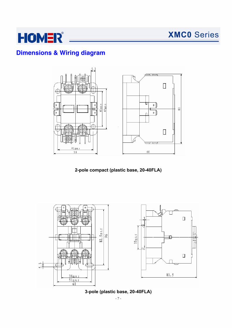
Dimensions & Wiring diagram
1-pole/1-pole+shunt (plastic base, 20-40FLA)
- 7 -
Dimensions & Wiring diagram
2-pole compact (plastic base, 20-40FLA)
3-pole (plastic base, 20-40FLA)

- 8 -
Dimensions & Wiring diagram
1- pole/1-pole+shunt (metal base, 20-40FLA)
2-pole compact (metal base, 20-40FLA)

- 9 -
Dimensions & Wiring diagram
2- pole (metal base, 20-40FLA)
3-pole (metal base, 50-63FLA)

- 10 -
Dimensions & Wiring diagram
3-pole (metal base, 75-90FLA)
3-pole (small frame, plastic base, 12-25FLA)
- 11 -
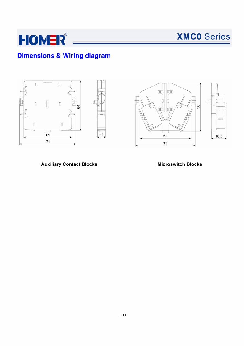
Dimensions & Wiring diagram
Auxiliary Contact Blocks Microswitch Blocks

- 12 -
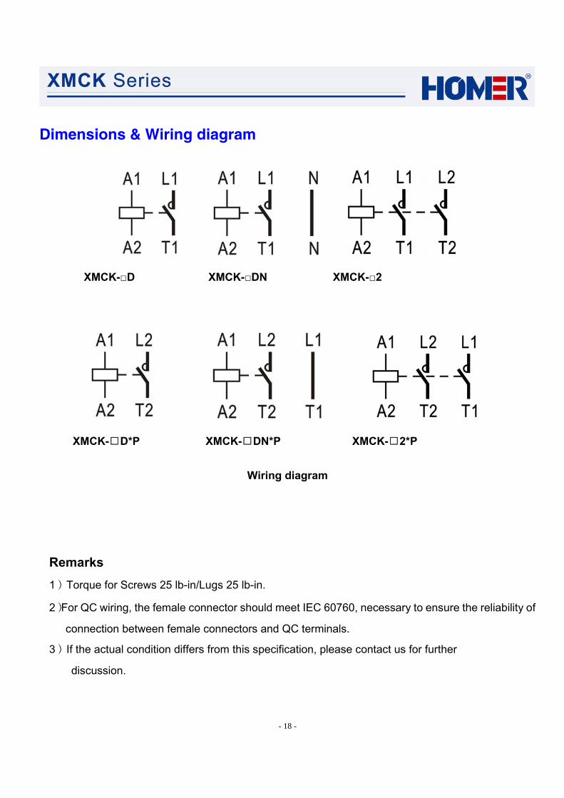
Dimensions & Wiring diagram
XMC0-□7 XMC0-□1 XMC0-□2
Standard Special Special
XMC0-□3(20-90FLA)
XMC0-□3/3B(small frame) XMC0-□8(small frame) XMC0-□9(small frame)
Wiring diagram
Remarks 1)Torque for Screws 25 lb-in/Lugs 25 lb-in for 20-40FLA types;
Torque for Screws 45 lb-in /Lugs 50 lb-in for 50-63FLA types; Torque for Screws 50 lb-in /Lugs 60 lb-in for 75-90FLA types; Torque for Screws 8 lb-in for Auxiliary Contact Blocks; Torque for Coil Screws 8 lb-in for 3-pole 20-40FLA types and 12 lb-in for 50-90FLA types; Torque for Main Screws 12 lb-in/Auxiliary Screws 8 lb-in/Coil Screws 8 lb-in for small frame types.
2)For QC wiring, the female connector should meet IEC 60760, necessary to ensure the reliability of connection between female connectors and QC terminals.
3)If the actual condition differs from this specification, please contact us for further discussion.

- 13 -
XMCK Series Definite Purpose Contactors
Description
HOMER XMCK series AC Contactors apply to control electric motor load of air conditioning compressor under 50Hz/60Hz(IEC standard AC-8a, AC-8b), rated insulation voltage ≤690V, rated current ≤40A(AC-8a or FLA). It also can be used for other home appliance and similar electric motor load. XMCK series AC contactors conform to UL 508 standard.
Features
1.Economic design solution. 2.Solid configuration design, electric pure steel magnet. 3.Easy coil change.. 4.Compact size and configuration. 5.Universal mounting plate allows an easy replacing to other brands. . 6.Heavy duty Silver Metal Oxide composition contacts with longer electrical endurance. 7.Coils are Class F (155 ) temperature insulated with wide range of voltages and 50/60Hz ratings.℃ 8.UL and CCC approved, some models SEMKO, KETI or TÜV plus.
Type model nomenclature - Ordering Information
XM C K - 40 DN 024 D P Z □ 1 2 3 4 5 6 7 8 9 10 Number digit 1: Manufacturer’s code
XM – Xiamen Hongmei Electronic Co., Ltd. Number digit 2: Product Type
C – Contactor Number digit 3: Design number
K – Design sequence number Number digit 4: Resistive Amps Rating(RES)– 25, 30, 40, 50
25 – 25A 30 – 30A 40 – 40A 50 – 50A (For XMCK-□2 only, no for XMCK-□D or XMCK-□DN type)

- 14 -
Number digit 5: Number of Poles – D, DN or 2. Number digit 5 D DN 2 Number of poles 1-pole 1-pole+shunt 2-pole
Number digit 6: Coil Voltage – 024, 120, 240 or blank, 277
Number digit 6 024 120 240 or blank 277
60Hz 24VAC 110-120VAC 208-240VAC 277VAC Coil voltage
50Hz 24VAC 110-120VAC 208-240VAC --- Number digit 7: Terminal – A, B, C or blank, D, E, F
A – Screw w/ quick connect B – Sems clamp w/ quick connect C or blank – Slotted & Hex head washer w/ quick connect D – Box lug w/ quick connect E – Box lug w/ quick connect (Line side)
Slotted & Hex head washer w/ quick connect (Load side) F – Slotted & Hex head washer w/ quick connect (Line side)
Box lug w/ quick connect (Load side) Number digit 8: Cover word – Blank, P
Blank – Cover word shows normal wiring diagram P – Cover word shows special wiring diagram (reference wiring diagram)
Number digit 9: Nameplate – Blank, T, Z Blank – Nameplate shows actual product rating T – Nameplate shows derated product rating Z – Nameplate shows upgraded product rating(for XMCK-40D or XMCK-40DN)
Number digit 10: Option Customer assigned suffix “X” where “X” may be any alphanumeric character or any combined alphanumeric character.
Characteristics
Conforming to standard IEC60947-4-1, GB14048.4, UL508
Approvals or Certificate UL(USR/CNR) and CCC Some models SEMKO, KETI or TÜV plus
Operating position Vertical (Metal base mounting)
operation ℃ -25℃ ~ +70℃ Ambient temperature
storage ℃ -40℃ ~ +70℃ Relative humidity 90-95%RH at 40℃ Pollution degree 3

- 15 -
Performance
XMCK- Poles D DN 2 Rated insulation voltage V 690 Rated operating voltage V 240/277,480 (60Hz) or 230,400 (50Hz) Full load ampere(FLA) A 20 25 30 40 Resistive Amps Rating(RES) A 25 30 40 50 Making capacity(230V cosφ0.45) A 12×FLA Breaking capacity(230V cosφ0.45) A 10×FLA Switching frequency op/h 360 Electrical endurance(ARI 780/790) cycle 100,000 Mechanical endurance(ARI 780/790) cycle 500,000
Pole Characteristics
Maximum Horsepower Full Load
Amps (FLA)
Number OfPoles
Line Voltage
Locked Rotor Amps (LRA)
Resistive Amps Rating (RES) Voltage Single
Phase
Catalog Number
20 1 240/277
480 600
120 100 80
25 240/277 1.5 XMCK-25D* XMCK-25DN*
25 1 240/277
480 600
150 125 100
30 240/277 2 XMCK-30D* XMCK-30DN*
25 2 240/277
480 600
150 125 —
35 240/277 3 XMCK-302*
30 1 240/277
480 600
150 75 50
40 240/277 2 XMCK-40D* XMCK-40DN*
30 2 240/277
480 600
180 150 —
40 240/277 3 XMCK-402*
40 1 240/277
480 600
240 160 100
50 240/277 3 XMCK-40D*Z XMCK-40DN*Z
40 30 —
2 240/277
480 600
240 150 —
50 240/277 3 XMCK-502*
Notes: All the models also could be marked or used for the actual applications which have less contact ratings than the certificated ratings. The rating can be voltage, FLA, LRA or RES.

- 16 -
Coil characteristics @ 25℃(Cold state)
Inrushed VA Sealed VA Sealed Watts Voltage Part number
60Hz 50Hz 60Hz 50Hz 60Hz Pick-up Drop-out
XMCK-□D/DN 32 36 8 10 4.5
XMCK-□2 40 45 11 13 5.5 ≤0.8Us ≥0.2Us
Notes: Us=24VAC 50/60Hz or 120VAC 50/60Hz or 220VAC/50Hz, 240VAC/60Hz or 277VAC/60Hz. Inrushed VA and Sealed VA test at Us.
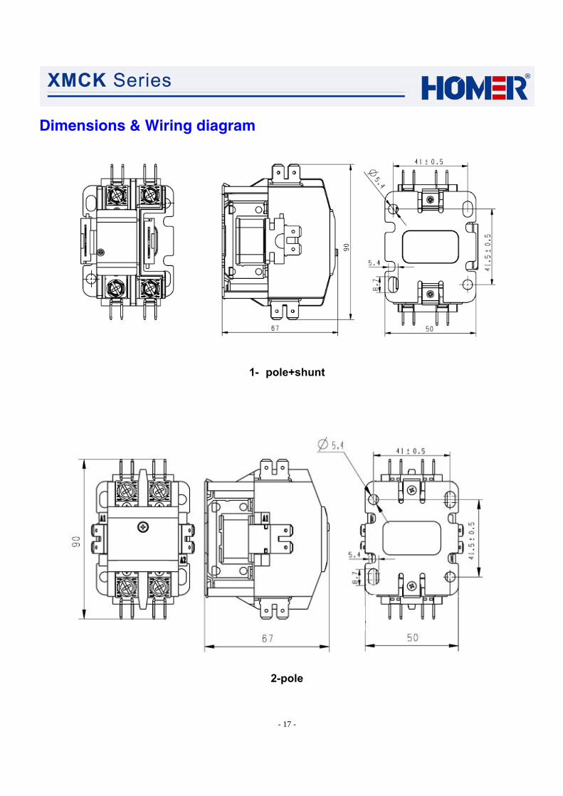
Dimensions & Wiring diagram
1- pole
- 17 -
Dimensions & Wiring diagram
1- pole+shunt
2-pole
- 18 -
Dimensions & Wiring diagram
XMCK-□D XMCK-□DN XMCK-□2
XMCK-□D*P XMCK-□DN*P XMCK-□2*P
Wiring diagram
Remarks
1)Torque for Screws 25 lb-in/Lugs 25 lb-in.
2)For QC wiring, the female connector should meet IEC 60760, necessary to ensure the reliability of
connection between female connectors and QC terminals.
3)If the actual condition differs from this specification, please contact us for further
discussion.

- 19 -
XMC2 Series AC Contactors
Description
HOMER XMC2 series contactors are developed by Hongmei, based on customer’s requirements for pursuing a high performance and reliability. It has wider range of coil voltage, better contact operating ability, higher thermal-resistance class and better performance in anti-shock and vibration than same level product. It applies to electric motor load control of compressor in air conditioner under 50Hz/60Hz, rated insulation voltage ≤ 690V, rated current ≤32A. (IEC standard AC-8a, AC-8b). It also can be used in power supply system for long distance making and breaking circuit, controlling electric motor load (IEC category: AC-3, AC-4). It is able to work with thermal relays to be a magnet starter assembled to protect circuit from over-load current.
XMC2 series contactors not only can meet high requirements for Air conditioning compressor and freezing container but also can be used for all kinds of power system. It’s flexible to attach auxiliary contact to meet all customers’ requirements and providing various contact arrangements: 3P, 3P+1NC, 3P+1NO, 2NO+2NC, 4P. XMC2 series conform to IEC60947, GB14048 and UL 508 standards.
Features
1. Unique structure of amortization system eliminates contact bounce. 2. Heavy duty Silver Metal Oxide composition contacts with longer electrical endurance. 3. Various contact arrangements meet requirements of different customer. 4. Interface available for Auxiliary contact and protection module. Easy to assemble. 5. The maximum ambient temperature can approach +80℃. 6. Excellent performance on anti- shock and vibration (acceleration can be 0~20G&40Hz without
failure). 7. Coils are Class H (180℃)insulated with wide range of voltages and 50/60Hz ratings. 8. Two types of coil terminal: double coil terminal and triple coil terminal. Easy to change. 9. Easy coil change. 10. Universal mounting plate allows an easy replacement to other brands. 11. Double “E” shaped Magnet Assembly provides optimal performance with lower power
consumption. 12. Effective dustproof structure.

- 20 -
Type model nomenclature - Ordering Information
Table 1 Full Load Amperes (FLA)
Code 12 18 30 32 Full Load Amperes (FLA) (A) 12 18 30 32
Table 2 Number of Poles
Code 3 4 8 9 2R Number of Poles 3 poles 4 poles 3 poles+1NC 3 poles+1NO 4 poles(2a2b)
Table 3 Coil Voltage
Code E F I L N 60Hz 24 110-120 208-240 277 440-480
Coil Voltage (V) 50Hz 24 110 208-220 230 380-415
Table 4 Coil Terminal Type
Code P S Coil Terminal Type Double coil terminal(Standard type, can be omitted) Triple coil terminal
·XM C 2 30 8
Design Sequence Number
Contactor
Xiamen Hongmei Electronics Co. Ltd.
- P 1LE
(Option in table 5)
Coil Terminal Type
Number of Poles
Coil Voltage
3Pole Auxiliary Contact Block
Full Load Amperes (FLA)
(Option in table 4)
(Option in table 3)
(Option in table 2)
(Option in table 1)

- 21 -
Table 5 Auxiliary Contact Block (ACB)
Code 00 1L 1R 2L 2R L1 R1 L2 R2 10 01 ACB None 1NC 1NC 2NC 2NC 1NO 1NO 2NO 2NO 1NC+1NO 1NC+1NO
Remark 1) at left at right at left at right at left at right at left at right at left at right 1) Standard type, can be omitted
Characteristics
Rated insulation voltage V 690
Conforming to standard IEC60947-4-1, GB14048.4, EN60947-4-1, UL 508
Approvals CCC Protective treatment TH Operating position Vertical
operation ℃ -25℃ ~ +70℃ Ambient temperature storage ℃ -40℃ ~ +70℃ Relative humidity 90-95%RH at 40℃ Pollution degree 3
contactor g 30 Shock resistance 1/2 sine wave=11 ms contactor g 30
contactor g 10 Vibration resistance 5 to 60 Hz contactor g 15
Performance
XMC2- Poles 3 4 8 9 2R Rated insulation voltage V 690 Rated operating voltage V 480/277(60Hz)or 400/230(50Hz) Full load ampere(FLA) A 12 18 30 32 Resistive load ampere(RLA) A 20 25 32 40 Making capacity(400V cosφ0.45) A 12×FLA Breaking capacity(400V cosφ0.45) A 10×FLA Switching frequency op/h 360 Electrical endurance(ARI 780/790) cycle 200,000 Mechanical endurance cycle 10,000,000

- 22 -
Pole Characteristics
Locked Rotor amps Power Full Load Amps
Resistive Amps
Per Pole 230/ 277V 480V 600V 230V
1 Phase480V
3 Phase 600V
3 Phase Poles
12 20 72 60 48 1.5 3 5
18 25 108 90 72 2 5
7.5
30 32 150 125 100 3 7.5 10 32 40 180 150 120 3 10 15
3P 3P+1NC 3P+1NO
4P(2a2b)
Auxiliary contacts block characteristics
Conventional thermal current (A) 10 Rated insulation voltage (V) 690
A600(AC-15) 230V/3A 380V/1.9A Rated operational current P600(DC-13) 110V/1.1A 230V/0.55A
Coil characteristics
Voltage Part number Inrushed VA
Sealed VA
Sealed Watts Pick-up Drop-out
XMC2-12~32 95 13.5 1.0 ≤0.8US ≥0.3US
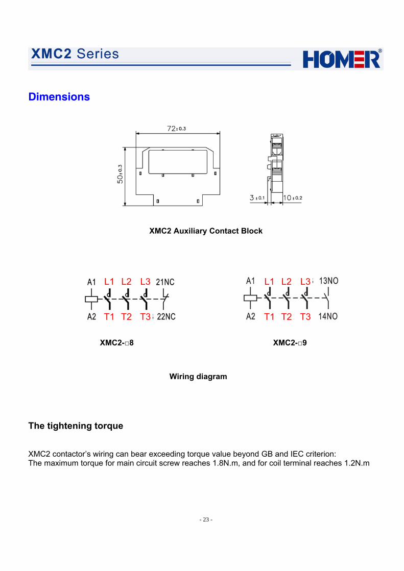
Dimensions
XMC2-12~32A(3P / 3P+1NC / 3P+1NO / 4P / 4P(2a2b)
- 23 -
Dimensions
XMC2 Auxiliary Contact Block
XMC2-□8 XMC2-□9
Wiring diagram
The tightening torque
XMC2 contactor’s wiring can bear exceeding torque value beyond GB and IEC criterion: The maximum torque for main circuit screw reaches 1.8N.m, and for coil terminal reaches 1.2N.m
L1 L2 L3
T1 T2 T3
L1 L2 L3
T1 T2 T3
-