« energetic macroscopic representation (emr) - emr.pdf“energetic macroscopic representation” 1....
TRANSCRIPT

1
EMR’16
UdS - Longueil
June 2016
Summer School EMR’16
“Energetic Macroscopic Representation”
« ENERGETIC MACROSCOPIC
REPRESENTATION (EMR) »
Prof. Alain BOUSCAYROL1, Prof. João P. Trovão1, 1 L2EP, Université Lille1, MEGEVH network, France
2 e-TESC, Université de Sherbrooke, Canada
Within the DL program of IEEE-VTS
2
« Energetic Macroscopic Representation (EMR) »
EMR’16, UdS Longueil, June 2016
- Outline -
1. EMR basic elements
• Source, accumulation and conversion elements
• Coupling and adaptation elements
2. EMR of a complete system
• Action and tuning path
• Association rules
3. Conclusion: towards control organization

2
3
« Energetic Macroscopic Representation (EMR) »
EMR’16, UdS Longueil, June 2016
real
system
system
model
system
representation
- Level of study -
system
simulation
model
objective
limited
validity range
organization
valuable
properties
behavior
study
prediction
4
« Energetic Macroscopic Representation (EMR) »
EMR’16, UdS Longueil, June 2016
real
system
representation
- Representation I/O -
Model objective:
“control”
causal &
systemic
organization
Highlight energetic
and systems properties
prediction
dynamical
models
Real-time
control &
Energy
management
forward
approach

3
EMR’16
UdS - Longueil
June 2016
Summer School EMR’16
“Energetic Macroscopic Representation”
1. « EMR basic elements »
6
« Energetic Macroscopic Representation (EMR) »
EMR’16, UdS Longueil, June 2016
- The different elements -
Energy sources
Energy storage
Energy conversion
Energy distribution
Only 4 energy functions
are required to describe
energy conversion systems
EMR = 4 graphical elements associated with the 4 energy functions

4
7
« Energetic Macroscopic Representation (EMR) »
EMR’16, UdS Longueil, June 2016
Sourceoval pictogram
background: light green
contour: dark green
1 input vector (dim n)
1 output vector (dim n)
- Energetic sources -
terminal elements which represent
the environment of the studied system
generator and/or receptor of energy
power system
reaction
action
upstream
source
downstream
sourcex1
y1
x2
y2
p1= x1. y1 p2= x2. y2
direction of
positive power
(convention)
n
i
ii yx
1
11
8
« Energetic Macroscopic Representation (EMR) »
EMR’16, UdS Longueil, June 2016
pload
qwind
wind
qwind [m3/s]
Pload [Pa]
bulbI
u
I
u
Wind
(air flow source)
generator energy
VDC
iBat
VDC
i
- Energetic sources: examples -
Battery
(voltage source)
generator and
receptor of energy
Ligthing bulb
receptor of energy
IC engine
(torque source)
generator
of energyTice
WICE
Tice
W
Tice-ref

5
9
« Energetic Macroscopic Representation (EMR) »
EMR’16, UdS Longueil, June 2016
Accumulatorrectangle with an oblique bar
background: orange
contour: red
upstream I/O vectors (dim n)
downstream I/O vectors (dim n)
- Accumulation elements -
internal accumulation of
energy (with or without
losses)
reaction
actionx1
y
y
x2
p1= x1. y p2= x2. y
causality principle
output(s) = input(s)
dtxxfy ),( 21
y = output, delayed with
regard to input changes
fixed I/O (causal description)
10
« Energetic Macroscopic Representation (EMR) »
EMR’16, UdS Longueil, June 2016
inductor
v1
v2
i
i
v1 v2
i
L
v
i2i1
C
capacitor
i1
i2
v
v
inertia
WJ
T2T1
W
T1
T2
W
W
stiffness
kW1 W2
TT
W1
W2
T
T
2 2
1iLE
2 2
1W JE
2 1
2
1T
kE
2 2
1vCE
- Accumulation elements: examples -
6
11
« Energetic Macroscopic Representation (EMR) »
EMR’16, UdS Longueil, June 2016
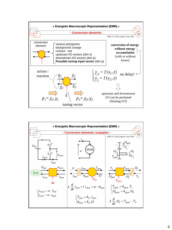
conversion
elementvarious pictograms
background: orange
contour: red
upstream I/O vectors (dim n)
downstream I/O vectors (dim p)
Possible tuning input vector (dim q)
- Conversion elements -
conversion of energy
without energy
accumulation
(with or without
losses)
action /
reaction x1
y1
y2
x2
p1= x1. y1 p2= x2. y2
),(
),(
21
12
zxfy
zxfy
z
tuning vector
no delay!
upstream and downstream
I/O can be permuted
(floating I/O)
12
« Energetic Macroscopic Representation (EMR) »
EMR’16, UdS Longueil, June 2016
kF
- Conversion elements: examples -
dcmdcmdcm euiridt
dL
VDCuconv
iloadiconv
VDC
iconv
uconv
s
iload
s
i
u DCM
Wgear
TgearT1
W2
W2
T3
kgear
3gear2 TTdt
dJ W
WF
F
ke
ikT
dcm
dcmdcm
idcm
u idcm
edcm
Tdcm
W
Wgear
T1
W2
Tgear
W2
T3
2geargear
1geargear
k
TkT
WW
m
loadconv
DCconv
imi
Vmu
Bat

7
13
« Energetic Macroscopic Representation (EMR) »
EMR’16, UdS Longueil, June 2016
coupling element
various overlapped pictograms
background: orange
contour: red
pairs of I/O vectors
N pairs, N-1 pictograms
- coupling elements -
distribution of energy
without energy
accumulation
without tuning
(with or without
losses)
action /
reaction x1
y1
p1= x1. y1
)x,..x(fy
...
)x,..x(fy
nnn
n
1
111no delay!
x2
xn
yn
y2
14
« Energetic Macroscopic Representation (EMR) »
EMR’16, UdS Longueil, June 2016
- Coupling elements: examples -
2
TTT
gearrdifldif
iarm
uarmDCM
iexc
uexc
Wexcdcm
armexcdcm
ike
iikT iarm
uarm
iexc
uexc
iarm
earm
Tdcm
W
eexc
iexc
Field winding DC machine
Mechanical differential
Wdiff
Tgear
Wlwh
Wrwh
Tldiff
Trdiff
Tldiff
Wrwh
Trdiff
Wlwh
Tgear
Wdiff2
ΩΩΩ rwhlwh
diff
8
15
« Energetic Macroscopic Representation (EMR) »
EMR’16, UdS Longueil, June 2016
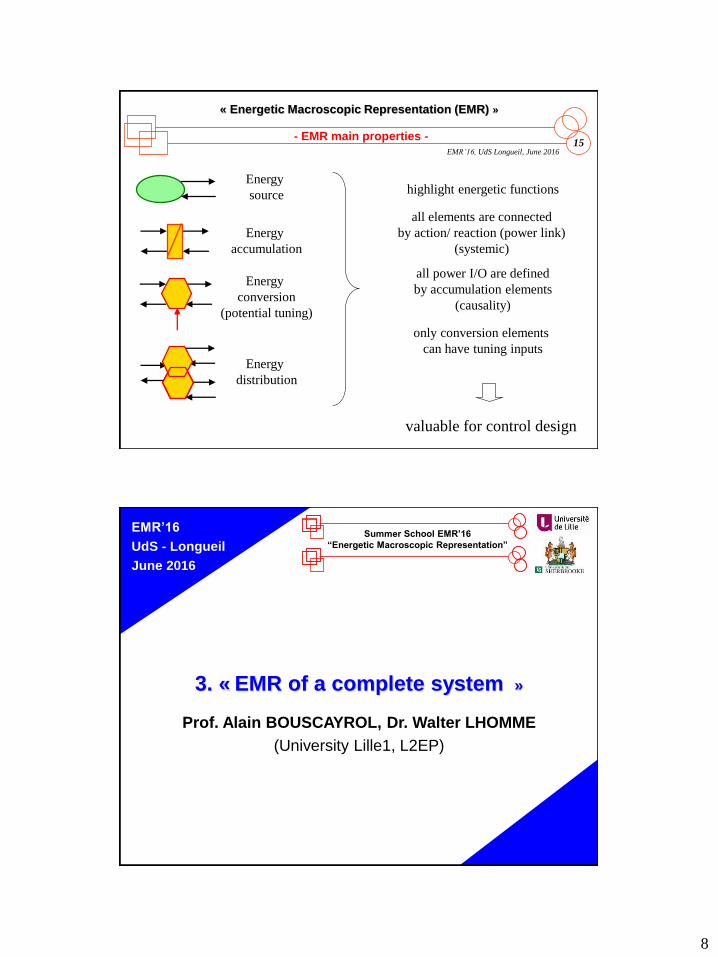
- EMR main properties -
Energy
source
Energy
accumulation
Energy
conversion
(potential tuning)
Energy
distribution
highlight energetic functions
all power I/O are defined
by accumulation elements
(causality)
only conversion elements
can have tuning inputs
all elements are connected
by action/ reaction (power link)
(systemic)
valuable for control design
EMR’16
UdS - Longueil
June 2016
Summer School EMR’16
“Energetic Macroscopic Representation”
3. « EMR of a complete system »
Prof. Alain BOUSCAYROL, Dr. Walter LHOMME
(University Lille1, L2EP)
9
17
« Energetic Macroscopic Representation (EMR) »
EMR’16, UdS Longueil, June 2016
OKy2
x2
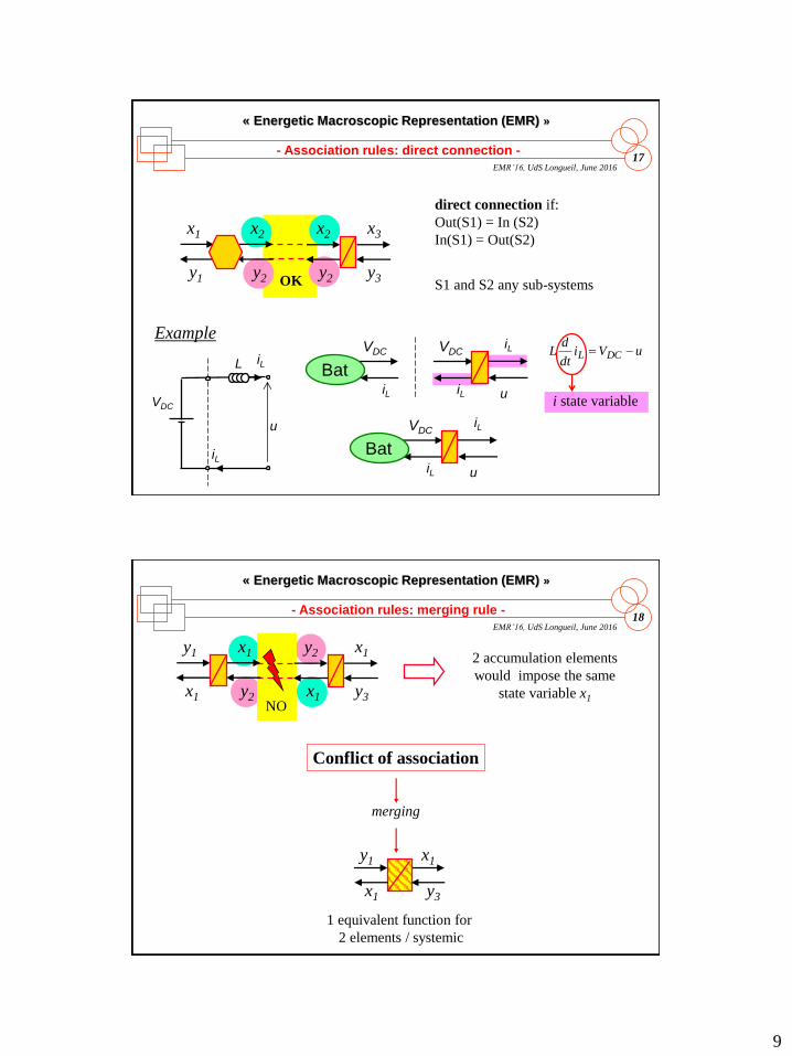
- Association rules: direct connection -
x2
y2y1
x1 x3
y3
direct connection if:
Out(S1) = In (S2)
In(S1) = Out(S2)
S1 and S2 any sub-systems
Bat
VDC
iL
u
VDC VDC
iLiL
iL
u
L iL
VDC
iL
iL
u
uVidt
dL DCL
i state variable
Example
Bat
18
« Energetic Macroscopic Representation (EMR) »
EMR’16, UdS Longueil, June 2016
x1
x1y2
y2
x1
y1 x1
y3
- Association rules: merging rule -
NO
2 accumulation elements
would impose the same
state variable x1
Conflict of association
merging
x1
y3x1
y1
1 equivalent function for
2 elements / systemic

10
19
« Energetic Macroscopic Representation (EMR) »
EMR’16, UdS Longueil, June 2016
x2
y2y1
x1 x3
y3
x’2
y’2y1
x1 x3
y3
- Association rules: permutation rule -
permutation possible if same global behavior:
strictly the same effects (y1 and x3) from the same causes (x1 , y3 and z)
z zx2
y2y1
x1 x3
y3
z
20
« Energetic Macroscopic Representation (EMR) »
EMR’16, UdS Longueil, June 2016
Assumptions:
J1 , J2 constant
no backslash
- Interest of rules -
W1W1
T2
T3
W2
T1
T4
W2
J1
J2
W1
W1
T2
T1
J1 W2
T3 W2
W2
T4
T3
J2
to solve conflict
of association
k
J1/k2
W1
T’2T1 W2
T3W2 W2
W2
T4
T3
J2
permutation
k
22
1eq J
k
JJ
W1
T’2T1
W2
T4W2
Jeqmerging
k
11
21
« Energetic Macroscopic Representation (EMR) »
EMR’16, UdS Longueil, June 2016
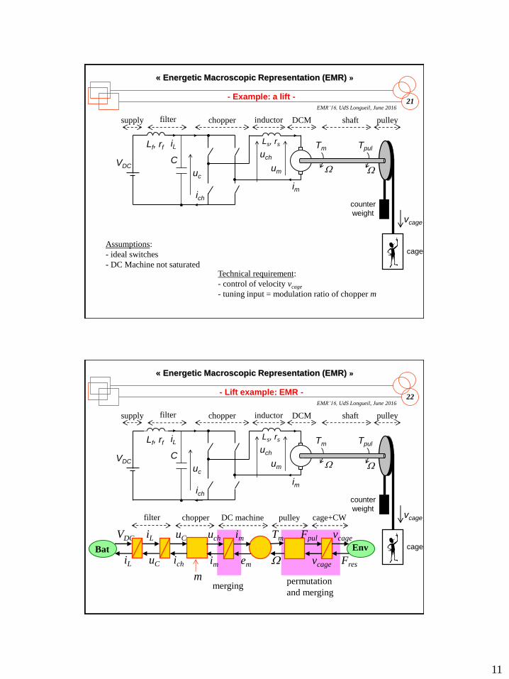
- Example: a lift -
Assumptions:
- ideal switches
- DC Machine not saturated
W
TmLs, rs
uch
um
ich
VDC
im
shaft pulleyDCMchoppersupply
counter
weight
cage
Tpul
vcage
filter
uc
iLLf, rf
CW
inductor
Technical requirement:
- control of velocity vcage
- tuning input = modulation ratio of chopper m
22
« Energetic Macroscopic Representation (EMR) »
EMR’16, UdS Longueil, June 2016
- Lift example: EMR -
W
TmLs, rs
uch
um
ich
VDC
im
inductor shaft pulleyDCMchoppersupply
counter
weight
cage
Tpul
vcage
filter
uc
iLLf, rf
CW
mmerging
permutation
and merging
VDC iL
iL uC
Bat Env
ich
uC
im
uch
em
im
W
Tm Fpul
vcage
vcage
Fres
filter chopper DC machine pulley cage+CW
12
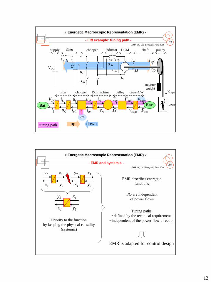
23
« Energetic Macroscopic Representation (EMR) »
EMR’16, UdS Longueil, June 2016
up down
- Lift example: tuning path -
W
TmLs, rs
uch
um
ich
VDC
im
inductor shaft pulleyDCMchoppersupply
counter
weight
cage
Tpul
vcage
filter
uc
iLLf, rf
CW
tuning path
VDC iL
iL uC
Bat Env
ich
uC
im
uch
em
im
W
Tm Fpul
vcage
vcage
Fres
filter chopper DC machine pulley cage+CW
m
24
« Energetic Macroscopic Representation (EMR) »
EMR’16, UdS Longueil, June 2016
x1
x1y2
y2
- EMR and systemic -
I/O are independent
of power flows
Tuning paths:
• defined by the technical requirements
• independent of the power flow direction
EMR describes energetic
functions
EMR is adapted for control design
x1
y1 x1
y3
x1
y2 x1
y3
Priority to the function
by keeping the physical causality
(systemic)

13
EMR’16
UdS - Longueil
June 2016
Summer School EMR’16
“Energetic Macroscopic Representation”« Conclusion »
EMR = multi-physical graphical description
based on the interaction principle (systemic)
and the causality principle (energy)
Basic elements = energetic function
sources, accumulation, conversion and distribution of energy
Association rules = holistic property of systemic
enable keeping physical causality in conflict of association
Applications
analysis, simulation, control organisation…
26
« Energetic Macroscopic Representation (EMR) »
EMR’16, UdS Longueil, June 2016
- Speaker & contributors -
Prof. Alain BOUSCAYROL
University Lille 1, L2EP, MEGEVH, France
Coordinator of MEGEVH, French network on HEVs
PhD in Electrical Engineering at University of Toulouse (1995)
Research topics: EMR, HIL simulation, tractions systems, EVs and HEVs
… and other colleagues from the control team of L2EP Lille
Prof. João P. Trovão
Université de Sherbrooke, e-TESC Lab., Qc, Canada
PhD in Electrical Engineering at University of Coimbra (2012)
Research topics: Electric Vehicles, Multiple Energy Storage, Energy Management

14
27
« Energetic Macroscopic Representation (EMR) »
EMR’16, UdS Longueil, June 2016
- Some references -
A. Bouscayrol, & al. "Multimachine Multiconverter System: application for electromechanical drives", European
Physics Journal - Applied Physics, vol. 10, no. 2, May 2000, pp. 131-147 (common paper GREEN Nancy, L2EP Lille
and LEEI Toulouse, according to the SMM project of the GDR-SDSE).
A. Bouscayrol, "Formalism of modelling and control of multimachine multiconverter electromechanical systems” (Texte
in French), HDR report, University Lille1, Sciences & technologies, December 2003
A. Bouscayrol, J. P. Hautier, B. Lemaire-Semail, "Graphic Formalisms for the Control of Multi-Physical
Energetic Systems", Systemic Design Methodologies for Electrical Energy, tome 1, Analysis, Synthesis and
Management, Chapter 3, ISTE Willey editions, October 2012, ISBN: 9781848213883
K. Chen, A. Bouscayrol, W. Lhomme, "Energetic Macroscopic Representation and Inversion-based control: Application
to an Electric Vehicle with an electrical differential”, Journal of Asian Electric Vehicles, Vol. 6, no.1, June issue, 2008,
pp. 1097-1102.
P. Delarue, A. Bouscayrol, A. Tounzi, X. Guillaud, G. Lancigu, “Modelling, control and simulation of an overall wind
energy conversion system”, Renewable Energy, July 2003, vol. 28, no. 8, p. 1159-1324 (common paper L2EP Lille and
Jeumont SA).
J. P. Hautier, P. J. Barre, "The causal ordering graph - A tool for modelling and control law synthesis", Studies in
Informatics and Control Journal, vol. 13, no. 4, December 2004, pp. 265-283.
W. Lhomme, “Energy management of hybrid electric vehicles based on energetic macroscopic representation”, PhD
Dissertation, University of Lille (text in French), November 2007 (common work of L2EP Lille and LTE-INRETS
according to MEGEVH network).