* dtic · * dtic ad-a253 437 flelecte jul 24992 c final report deformation and damage mechanisms in...
TRANSCRIPT

* DTICAD-A253 437 flELECTE
JUL 24992
CFinal Report
DEFORMATION AND DAMAGE MECHANISMSIN HIGH TEMPERATURE COMPOSITES
WITH DUCTILE MATRICES
by
George J. Dvorak and Yehia A. Bahei-El-Din
Department of Civil and Environmental Engineeringand
Center for Composite Materials and StructuresRensselaer Polytechnic Institute
Troy, New York 12180-3590
Submitted to
Air Force Office of Scientific ResearchBoling Air Force Base, Washington, DC
1.
Contract Number AFOSR-88-0150
June 1992 92-1991192-1991

REPORT DOCUMENTATION PAGE omA,;
&-ft~ ffaE~Mftts"eq tft* aa AO M U :e %E' q a. too (lIn cti of ceffqll ,7 e.qt" e~a*a .n
1. AGENCY USE ONLY (Lofovof 0041,K) 2. REPORT OATE 3. RI R 1 N OATES COVERED
4L TiTLE AND suaTITLE S. FUNDING MUIGRSDeformation and Damage Mechanisms in High Temperat ur C-AOR-805Composites with Ductile MatricesC-AFS8-05
6*AUTHOP4S)George J. Dvorak and Yehia A. Bahei-El-Din
7. PERFoRmIG ORGANIZATION NAME(S) AND AOORESSS) S.& PERFORMIN ORGANIZATIONI Department of Civil and Environmental Engineering and REPORT NUMBERCenter for Composite Materials and StructuresRensselaer Polytechnic Institute AFOSR-TR. 07 4Troy, New York 12180-3590
9. SPONSONIN~i MONITORING AGENCY NAME(S) AND AOOREASS(ES) 1I. WPONSO01/ MONITORINGDr. Walter Jones 7/ AGENC REPOR NUM11ER1
Air Force Office of Scientific Research dBolling Air Force Base, Washington DC 20332
1.SUPPLEMNTAAY NOTES
2&a OISTNIUTIONI AvAiLAUIUTY STATEMENT 12L OISTROUUI10 CODE
Distribution unlimited.
I I& ASSTRACT (A&wmuM 200 woijWThis resport presents a summary of the theoretical and experimental work
performed in our research program on deformation and damage of high temperaturecomposites. The theoretical part focused on two areas; modeling of fatiguedamage in metal matrix composite and laminates by shakedown and nonlinearoptimization, and refinement of the unified viscoplasticity theory formulatedlast year for homogeneous materials, in order to model certain phenomena observedI in high temperature experiments of unreinforced metals. Implementation of thenew viscoplasticity theory for the phases in the Periodic Hexagonal Array modelfor unidirectional composites was an important part of the research. Progressin these theoretical aspects of the program is summarized. The report alsoI describes achievements in the experimental program.
I 14. EESC EM IS NUMBER Of PAGESComposite materials, damage accumulation, 57viscoplasticity theory 16 cOam
17. SEJT CLASSWWIATIN I& sEOJNtY CLASSWICAriON 11L SEOJEIT OQASpICATION aR uMTATON OF ABSTRACTOf RE1PO11T OP Trd PAGE Of A&STRACT
Unclassified Unclassifie Unclassified SARI ~ ~ 7[TG.ZO-S Sta ra Ofom 2"0 (Rev 2.69)4).4 %4"1ZW550 0-u.00 w am to 3.
IL kkIGENERAL INSTRUC70NS FOR COMPLE"MNG SF 298
Tho Report Documnentation Pa3ge (ROP) s ..ised ni announcirg and cataloging reports. it s rrcor.artthat triis information no consistent wittl :1. 'est af tme report. oarticuhlarly n*e cover and title ciate.instructions for filling in eadi bici of ttle form follow. it is imortant !a stay within thell lines to mettoptical scanning requirements.
Blacki1. Agency Use Only (Leave blank. Block 122. 0'Stribution/Availability Statement.Bloc L epor Dae. ull ublcatin dte enotes PuOiie availaoiiity or limitations. Citt anySlac 2.~eort ~at. Fll ublcaton ateavailability to tne public. Enter additional
irlclidiiig day. month, and year, if availabie (e.g. I limitations or soeciai markings in all capitals (e.g.IJan 88). Mut cite at least tio year. NOFORN~, REL, TAM).
Block 3. Tva. of Report and Oat"s Covered. 000- See 0000 5230.24, 'DistributionState whether report is interim. final, etc. if Statements on Technicalapplicable, ene imlsv report dates (e.g. 10Oouets20..Jun 87- 30 Jun 66). aouthorties
efockC4 foandgj tj. A title is taken trom AS See Handbookt NMS2002the part of the report that provides the most "TS - Leave blank.meaningful and complete information. Whon areport is prepared in more than one volume. Block__ 12.DsrbuinCdrepeattho primary title. add volume number, and 1b.itruioCo.include subtitle for the specific volume. On 00-Laebakclassified documents enter the title classification 000 Eae blanstiutoncteo.e
in paenthses.from the Standard Distribution forMok kS. Funding Numbers. To include contract Unclassified Scientific and Technicalland grant numbers; may include program Reports.Iolement number(s). project number~s). task NASA - Leave blank.number~s), and work unit number(s). Us* the NTIS - Leave blank.following labels.c -Contract PR.Prollect S1lack 13. Abtrt Include a brief (MawMum6 Grant TA -Task 200 words) factall summary of the most1111 Program WU -Work Unit si gni fi cant inmformation containeod i n the report.I
Element Accession No.
Block 6. Author(s). Name(s) of person(s) Slack 14. juoc~rs Keywords or phrasesresponmsible for writing the report. performing identifying major subiects in the report.the research, or credited with the content of thereport. if editor or compiler, this should followthe name(s). Slock I1S. Number of PlMe Enter the total
number Of Pages.IMock 7. Performing Oraization Name(s) andAddress~nk. Self-explanatory. Stock 16. Prc~oo Enter appropriate priceBlock L. PerforinA Organization Revnr code, (NTIS oniy).Number Enter the unique alphanumenic reportnumber(s) assigned by the organization Blocks M1.1, Security Classification' Self-
perorii m th f potexplanatory. Enter U.S. Secunt Classification in
Mo1kck 9. SponsoimNglonitarimagericy Name(s) accordance with U.S. Security Regulations; (i.e.,and ddrno)Selfexpanatry.U NCLASSIFIED). If farm contains classifiedIE!L~~Ur32I~flk Sefepaaoy nformation. ftawq)dasflcation on the top and
Mlock 10. SadinsonnoeMonitarin Agenicy bottom of the page.Reggrt Number. (if known)
lack I1I. Suialemenarv Notg Enter Black 20. Limitation of Abts~This block mustinform ..ation not included elsewhere such as: be com pleted to aign a limitation to thePrepared in cooperation with ... ; Trans. of ... ; To be abstract. Entersethier UL (unlimited) or SAR (samepublished in.... When a report is revised, include as reoort). Anentryin this bock is necessary ifIa staterment wiiet~r the new report supersec es tio aostract is to be limited. if biank, the abstractat suOclements tre oider reocirt. s 3ssurree -o be urtimited.

TABLE OF CONTENT-,
Page
ABSTRACT iii
1. INTRODUCTION 1
2. THEORETICAL WORK 2
2.1 Thermoviscoplasticity of Fibrous Composites 2
2.1.1 Micromechanical Models 22.1.2 Uniform Fields and Phase Eigenstrains 4
in Heterogeneous Media 62.1.3 Constitutive Equations of the Phases 102.1.4 Comparison with Experiments 112.1.5 Rate Dependent Analysis of Metal
Matrix Composite Systems2.1.6 Numerical and Experimental Results 16
2.2 Fatigue Damage in Metal Matrix Composites 17
3. EXPERIMENTAL WORK 20
3 1 Equipment 203.2 Specimens 21
ACKNOWLEDGEMENT 21
REFERENCES 22
TABLES 24
FIGURES 25
LIST OF PUBLICATIONS 44
LIST OF PRESENTATIONS Ao".04 oa For 45
LIST OF PROFESSIONAL PERSONNEL 1--. 1 t&I48
APPENDIX Ua.-nuuneod CJu. Lo at i r
_..Av! ab lt Codes
i V__. ,cLr

ABSTRACT
This report presents a summary of the theoretical and experimental work performed
in our research program on deformation and damage of high temperature composites. The
theoretical part focused on two areas; modeling of fatigue damage in metal matrix
composite and laminates by shakedown and nonlinear optimization, and refinement of the
unified viscoplasticity theory formulated last year for homogeneous materials, in order to
model certain phenomena observed in high temperature experiments of unreinforced
metals. Implementation of the new viscoplasticity theory for the phase sin the Periodic
Hexagonal Array model for unidirectional composites was an important part of the
research. Progress in these theoretical aspects of the program is summarized. The report
also describes achievements in the experimental program.
,oo1i
1. INTRODUCTION
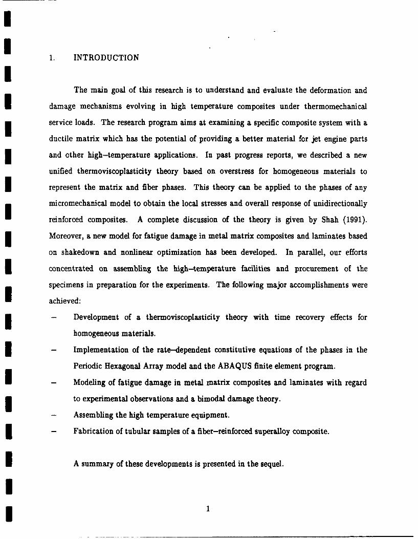
The main goal of this research is to understand and evaluate the deformation and
damage mechanisms evolving in high temperature composites under thermomechanical
service loads. The research program aims at examining a specific composite system with a
ductile matrix which has the potential of providing a better material for jet engine parts
and other high-temperature applications. In past progress reports, we described a new
unified thermoviscoplasticity theory based on overstress for homogeneous materials to
represent the matrix and fiber phases. This theory can be applied to the phases of any
micromechanical model to obtain the local stresses and overall response of unidirectionally
reinforced composites. A complete discussion of the theory is given by Shah (1991).
Moreover, a new model for fatigue damage in metal matrix composites and laminates based
on shakedown and nonlinear optimization has been developed. In parallel, our efforts
concentrated on assembling the high-temperature facilities and procurement of the
specimens in preparation for the experiments. The following major accomplishments were
achieved:
- Development of a thermoviscoplasticity theory with time recovery effects for
homogeneous materials.
- Implementation of the rate-dependent constitutive equations of the phases in the
Periodic Hexagonal Array model and the ABAQUS finite element program.
- Modeling of fatigue damage in metal matrix composites and laminates with regard
to experimental observations and a bimodal damage theory.
- Assembling the high temperature equipment.
- Fabrication of tubular samples of a fiber-reinforced superalloy composite.
A summary of these developments is presented in the sequel.
I 1
2. THEORETICAL WORK
2.1 Thermoviscoplasticity of Fibrous CompositesI2.1.1 Micromechanical Models
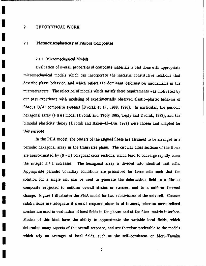
Evaluation of overall properties of composite materials is best done with appropriate
imicromechanical models which can incorporate the inelastic constitutive relations that
describe phase behavior, and which reflect the dominant deformation mechanisms in the
microstructure. The selection of models which satisfy these requirements was motivated by
our past experience with modeling of experimentally observed elastic-plastic behavior of
fibrous B/Al composite systems (Dvorak et al., 1988, 1990). In particular, the periodic
hexagonal array (PHA) model (Dvorak and Teply 1985, Teply and Dvorak, 1988), and the
bimodal plasticity theory (Dvorak and Bahei-El-Din, 1987) were chosen and adapted for
this purpose.
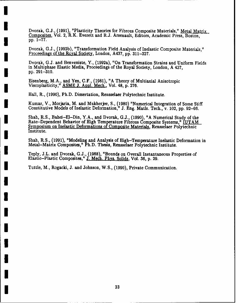
In the PHA model, the centers of the aligned fibers are assumed to be arranged in a
I periodic hexagonal array in the transverse plane. The circular cross sections of the fibers
are approximated by (6 x n) polygonal cross sections, which tend to converge rapidly when
the integer n > 1 increases. The hexagonal array is divided into identical unit cells.
Appropriate periodic boundary conditions are prescribed for these cells such that the
solution for a single cell can be used to generate the deformation field in a fibrous
composite subjected to uniform overall strains or stresses, and to a uniform thermal
change. Figure 1 illustrates the PHA model for two subdivisions of the unit cell. Coarser
subdivisions are adequate if overall response alone is of interest, whereas more refined
meshes are used in evaluation of local fields in the phases and at the fiber-matrix interface.
Models of this kind have the ability to approximate the variable local fields, which
determine many aspects of the overall response, and are therefore preferable to the models
which rely on averages of local fields, such as the self-consistent or Mori-Tanaka
2
approximations. Typically, the solution is found with the ABAQUS finite element
program. However, in the present research the problem was reformulated as described
below, hence the solution can be now found in a more efficient manner, without inelastic
finite element routines.
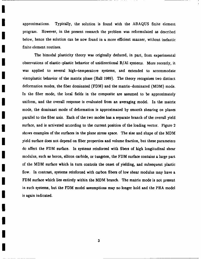
The bimodal plasticity theory was originally deduced, in part, from experimental
observations of elastic-plastic behavior of unidirectional B/Al systems. More recently, it
was applied to several high-temperature systems, and extended to accommodate
viscoplastic behavior of the matrix phase (Hall 1989). The theory recognizes two distinct
deformation modes, the fiber dominated (FDM) and the matrix-dominated (MDM) mode.
In the fiber mode, the local fields in the composite are assumed to be approximately
uniform, and the overall response is evaluated from an averaging model. In the matrix
mode, the dominant mode of deformation is approximated by smooth shearing on planes
parallel to the fiber axis. Each of the two modes has a separate branch of the overall yield
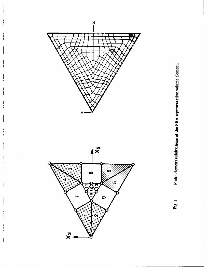
surface, and is activated according to the current position of the loading vector. Figure 2
shows examples of the surfaces in the plane stress space. The size and shape of the MDM
yield surface does not depend on fiber properties and volume fraction, but these parameters
do affect the FDM surface. In systems reinforced with fibers of high longitudinal shear
modulus, such as boron, silicon carbide, or tungsten, the FDM surface contains a large part
of the MDM surface which in turn controls the onset of yielding, and subsequent plastic
flow. In contrast, systems reinforced with carbon fibers of low shear modulus may have a
FDM surface which lies entirely within the MDM branch. The matrix mode is not present
in such systems, but the FDM model assumptions may no longer hold and the PHA model
is again indicated.
3
I
2.1.2 Uniform Fields and Phase Eigenstrains in Heterogeneous Media
In a series of recent papers, Dvorak (1983, 1986, 1987, 1990a) examined the
consequences of his discovery of the existence of uniform strain fields in heterogeneous
media. The recent papers (1990, 1992a, 1992b), and a related review paper (Dvorak 1991),
establish connections between mechanical and eigenstrain-induced local fields, and regard
plastic strains as phase eigenstrains. A solution scheme for the PHA and FDM models was
developed as a result of this investigation. .
The new method may be summarized as follows. Consider a representative volume
of the composite aggregate under uniform overall stress "0 or strain E, and a uniform
thermal change dO. A subdivision of the RVE is made such that in each subelement
r = 1, 2,...N, the actual local field is approximated by uniform stress, and the stress field in
the entire domain becomes piecewise uniform. Some initial loading has taken place in the
elastic and inelastic deformation ranges. Then, an increment of overall uniform strain di
or stress da is applied from the current state. The total strain increment der in each
subelement is decomposed into elastic strains Ardi caused by external loads, and total
strains which incorporate the local (uniform) inelastic strains together with the elastic
strains transmitted from all other subelements. The same decomposition is applied to the
local stresses:
d~r = Ar d6 + ar dO + D rs MsP, (i)
I
dorr = Br dj + br d + F r da! (2)
SMdors = Ls d4p ,
where Ar is strain concentration factor, ar is thermal strain vector, and Ls is the elastic
4
stiffness. The tensors Drs and Fs are eigenstrain and eigenstress concentration factors
which evaluate the average strain or stress in subelement r due to a single uniform unit
eigenstrain or eigenstress in subelement s, while the composite is fully constrained but not
otherwise loaded. This is combined with the phase constitutive equation, evaluated in each
subelement at the current local stress. In particular, the total strain increment is
additively decomposed, dEr = de, + de r , and the inelastic part takes the form
dEP = ( X r- Mr) dot + (4ur - mr) dO,I (3)dP = Gr dor + gr dO,
where X denotes the instantaneous compliance, M the elastic compliance, M the
instantaneous coefficient of thermal expansion, and mr the elastic coefficient of thermal
expansion. Local stresses in the subelements are then expressed as
dorr + XFrs Ls (Gs dor. + gr dO) = Br d'o + br dO. (4)
I 531
This is a system of N equations for the unknown local stresses. Note that the
transformation concentration factors are constant for a given RVE, and easily evaluated by
elastic analysis. The solution of (4) can be readily utilized in evaluation of local and
overall strains as follows:I-dr = (Mr +GOdr),
I dr = Cr dCr, d - p " d= -Mc d,
521
I
which gives the overall plastic strain increment under d. Particularly simple forms of the
I above procedure follow for two-phase systems, which are of interest in implementations of
the FDM model.
Additional applications of the uniform field concept have been made in development
of general relations between mechanical and eigenstrain concentration factors, and of
universal connections between overall and phase moduli, and also between coefficients of
the concentration factors themselves (Dvorak 1990). Of particular interest in the present
work is an exact analysis of the effect of thermal hardening in two-phase systems (Dvorak| 1991).
2.1.3 Constitutive Equations of the Phases
I To reflect the particular inelastic behavior of ductile high-temperature composites,
it is necessary to introduce into the analysis the appropriate viscoplastic constitutive
I relations of the constituent phases. We assume the phases to be homogeneous, the matrix
I elastically isotropic, and the fiber transversely isotropic. Either phase may exhibit
nonlinear response under thermomechanical loads which exceed the elastic limit of the
material. In this case, however, the present theory requires the material to be elastically
isotropic.
The total strain rate, iij, is divided into elastic, thermal and inelastic components:
I .e .t . (Eij = Eij + eij + fij • (6)
Considering isotropic materials and assuming the thermoelastic properties to be
temperature-dependent, the elastic and thermal strain rates are given by
E j i (0) rkl i i 1, (7)
I 6
t
ij = [(d Mijk1(O)/d0) okl + mij(O)] 0, (8)
mij(O) = bij it(O) , (9)
Ie
where 0 is the current temperature, Mijkl(O) is the elastic compliance, and at(O) is the
I coefficient of thermal expansion.
The inelastic part of the strain is found with the help of a viscoplasticity theory
I which incorporates the isothermal formulation by Eisenberg and Yen (1981). Our research
I in the past year concentrated on modifying the theory to include thermal loads,
temperature-dependent properties, and thermal time recovery. In what follows, we
I summarize the constitutive equations developed for rate-dependent deformation.
We assume the existence of an equilibrium yield surface which is the locus of all
I stress states that can be reached form the current state by purely elastic deformation.
Inelastic deformation develops only when the stress point lies outside the equilibrium yield
surface. In the presence of kinematic and isotropic hardening, a Mises form of the current
equilibrium yield surface can be written as
I f - i)(sij - Y Q) =0 , (1)
I where 8ij is the deviatoric stress, aij denotes the center of the yield surface, Y = Y(O) is
the yield stress in tension, which is independent of the loading rate, and Q is an isotropic
hardening function. The latter can be written as a function of the accumulated inelastic
I strain as
Q - Q(8, p) - Q(O)[I-e - 9 ), (11)
Fo G= fci d? fd(P.dePj; dfck 0. (12)
0 0
I 7
IT~ie functions Qa(O) and q(O) are material parameters and d p is effective inelastic strain
increment.
I The equilibrium stress, sj, which lies on the yield surface, is found from (10) as
I ~[ Y(0) + Q( 0)]2
S~l V.2Y ) = (sij - aij) +I aij. (13)3 = [ 3(Skl - Ckl)(Skl -akl)
The effective overstress, R, is a measure of the distance between the actual stress point, sij,
and the equilibrium stress point, sj. It vanishes if the stress point lies on or inside the
yield surface. In particular
R = [ (sij -stj)(sij- s)] iff> 0, (14)
R = 0 if f<0. (15)
IThe inelastic strain rate is assumed in the form of a power law of the overstress:I| j= -7 k(0) RP('" nij(svtj), (16)
where the functions k(0) and p(0) are assumed to be material parameters and nij is the unit
normal to the equilibrium yield surface (10) at the current equilibrium stress point.
The rate of translation of the center of the yield surface, &ij, is expressed as
f7k [H(O) - aQ/?n]k - - la-Cr(0) - 'r (aij/ - ) ,
(17)
8I
8
I
=( ). (18)
Here, H(0) is the tangent modulus of the inelastic stress-strain curve, and Vij specifies the
direction of translation of the yield surface in the absence of static time recovery. This
recovery is given by the second term in (17) and may be active even when the material is
elastic. It is caused by rearrangement of dislocations by climb and recrystallization from
annealing and is more pronounced at high temperatures. The functions c4{8) and m,(0) are
material parameters. Thermal recovery effects on the isotropic hardening rate Q (see
eq. (11)) can be also considered in the model; Shah (1991). This is omitted here for
brevity, we note, however, that description of this effect require four additional material
parameters which may depend on temperature.
A bounding surface is used to establish the instantaneous tangent modulus H and to
describe accurately the cyclic behavior of the material, Fig. 3. This surface is derived as an
isotropic expansion of the equilibrium yield surface. During inelastic deformation, the
bounding surface translates in the stress space and exhibits isotropic changes as well.
Translation of the bounding surface is dictated by the requirement that the yield surface
and the bounding surface have a common normal when they become in contact. Details of
this kinematic hardening rule are given by Dafalias and Popov (1976). In analogy with the
equilibrium yield surface, thermal time recovery of isotropic as well as kinematic hardening
of the bounding surface can be included in the model.
The instantaneous tangent modulus, H, is found as a function of the distance, 6,
between the equilibrium stress, st, and a corresponding point on the bounding surface, 8ij,
with unit normal nij(iij) = nij(Svj):
H(0) = H(0) + h() [/(in - 6)], (19)
9

6 =[~(S.- - St) ( stj)] (20)Ii JThe parameters HO(0) and h(0) need to be determined experimentally.
2.1.4 Comnarison with Experiments
The preceding theory was used to computed the response of unreinforced Ti-15-3
I under uniaxial tension which was tested by Tuttle, Rogacki and Johnson (1990). The tests
were conducted at room temperature, 482"C, and 649"C. At each temperature, two
tension tests were performed, one under stress-controlled loading at stress rate of
2.6 MPa/s, the other under strain-controlled loading at strain rate of 10 4/s. The
strain-controlled test consisted of a number of loading and relaxation periods. The
objective of this test was to determine the inelastic equilibrium stress-strain curve.
The parameters of the model found by matching the stress-controlled experiments
and the equilibrium response are shown in Table 1. The parameters with top bar
I correspond to the bounding surface and have the same meaning of their yield surface
counterparts. For example, Y is the 'radius' of the bounding surface, and qa, q are
material parameters related to the bounding surface isotropic hardening function q which
is similar in form to the yield surface isotropic hardening function Q given in eq. (11).
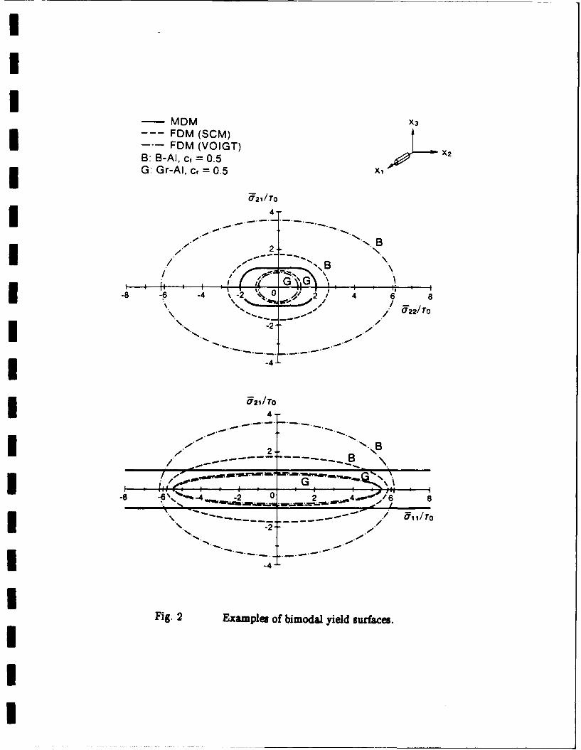
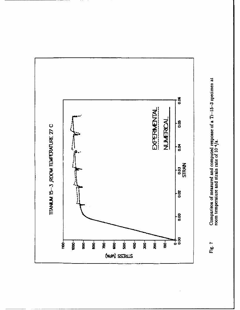
I The measured and computed responses are shown in Figs. 4--6 for the
stress-controlled tests and Figs. 7-9 for the strain-controlled tests. The agreement is
remarkably satisfactory. In particular, the theory replicates the descending portions of the
stress-strain curves under strain-controlled loading when the specimen is reloaded
following each relaxation period, Figs. 7-9.
110
2.1.5 Rate Dependent Analysis of Metal Matrix Composite Systems
The elastic deformation region of fibrous composites with metallic matrices is
reduced considerably at high temperatures. The individual phases, and hence the
composite aggregate become sensitive to the rate at which the overall temperature or
mechanical loads are applied and to other time dependent processes. Under sustained
loads, the response of these materials is also time dependent.
The local fields arising in the composite during thermomechanical loading are highly
nonuniform. As a result, stress and strain rates may vary from point to point in the
material, with the steepest gradients occurring at the interface between the fiber and the
matrix. These nonuniformities and gradients in local stress rates affect the overall loading
of the composite, those regions with very high stress or strain rates remain stiff as a result
of the dependence of instantaneous properties on the loading rates. This may cause even
higher stress concentrations in these areas, which are usually close to the interface of the
fiber and matrix, and may result in debonding or matrix cracking. Again, during overall
relaxation or creep, high inelastic strain rates will exist in the same regions due to effect of
prior loading history. This results in a redistribution of stresses within the phases which is
then bound to have an effect on the subsequent overall behavior.
All these aspects of high temperature deformation of metal matrix composites must
be considered in structural analysis. The only recourse in this case is the use of
micromechanics and in particular those models which assume nonuniform or at most
piecewise uniform local fields. The response of silicon carbide-titanium 15-3
unidirectional composites, at high temperatures, was analyzed using the periodic hexagonal
array (PHA) model outlined in Fig. 1. The thermoviscoplastic constitutive theory for the
deformation of the matrix phase recovery developed and tested in §2.1.3, was extended by
Shah (1991) to include thermal time. The temperature dependent material properties
required for the theory were evaluated in op. cit. from experiments on unreinforced
titanium 15-3.
11
The thermoviscoplastic constitutive equations were implemented in a subroutine to
be interfaced with the ABAQUS finite element code. The purpose of this subroutine was
to compute the material stiffness and stress increment for a given strain increment. The
purpose was to compute the material stiffness and stress increment for a given strain
increment. The subroutine would be called by the ABAQUS main program at each
integration point in the finite element mesh and for every loading increment. The actual
assembling of element stiffnesses, computation of displacements from the applied nodal
forces and conversion of these into strain increments was performed by the ABAQUS
program. Integration of the overall solution was performed in the main program using the
Newton-Raphson method.
The following information is provided to ABAQUS via UMAT at each material
integration point: Given the stress, total elapsed time, strain increment, time interval in
which the strain increment is applied, temperature at the start of the increment,
temperature increment, and all user defined solution dependent variables at the start of the
increment, the UMAT subroutine must return the stress, and the instantaneous stiffness at
the end of the increment as well as update all solution dependent variables. Solution
dependent variables are those which change with time and affect the computations in the
next increment. Examples are the location and size of the yield and bounding surfaces and
the accumulated inelastic strain.
A flowchart of the overall iteration scheme of ABAQUS is provided in Fig. 10, and
the corresponding overall stress-strain diagram of the Newton-Raphson procedure is
shown in Fig. 11. The steps involved in the entire procedure for computing the overall
response are outlined below:
Step 1: Input material properties, one set at each temperature, mechanical and thermal
loading history, initial temperature, initial time step for global integration and initial time
step for local integration.
12
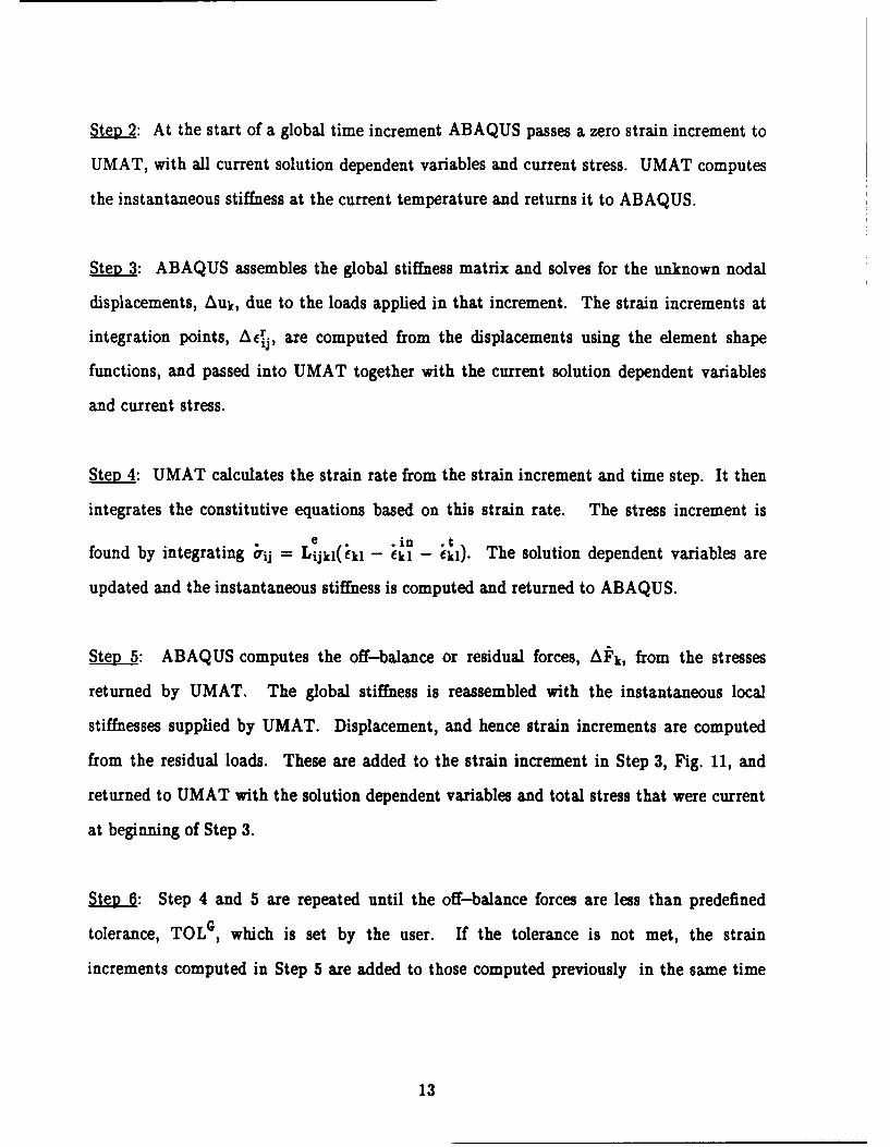
Step 2: At the start of a global time increment ABAQUS passes a zero strain increment to
UMAT, with all current solution dependent variables and current stress. UMAT computes
the instantaneous stiffness at the current temperature and returns it to ABAQUS.
Step 3: ABAQUS assembles the global stiffness matrix and solves for the unknown nodal
displacements, Auk, due to the loads applied in that increment. The strain increments at
integration points, Acij, are computed from the displacements using the element shape
functions, and passed into UMAT together with the current solution dependent variables
and current stress.
SteD 4: UMAT calculates the strain rate from the strain increment and time step. It then
integrates the constitutive equations based on this strain rate. The stress increment is
e .in *tfound by integrating 1rij = Lijkl(ikl - ik 1 - k). The solution dependent variables are
updated and the instantaneous stiffness is computed and returned to ABAQUS.
Step 5: ABAQUS computes the off-balance or residual forces, AFk, from the stresses
returned by UMAT. The global stiffness is reassembled with the instantaneous local
stiffnesses supplied by UMAT. Displacement, and hence strain increments are computed
from the residual loads. These are added to the strain increment in Step 3, Fig. 11, and
returned to UMAT with the solution dependent variables and total stress that were current
at beginning of Step 3.
Step 6: Step 4 and 5 are repeated until the off-balance forces are less than predefined
tolerance, TOLG , which is set by the user. If the tolerance is not met, the strain
increments computed in Step 5 are added to those computed previously in the same time
13

increment. If the tolerance is met, all variables are updated and Steps 2 through 6 are
repeated for the next time increment.
Two numerical integration schemes for systems of first order ordinary differential
equations of the form ii = f(y1 ,...yn,t), were used in Step 4 above. One was the explicit
fourth order Rung-Kutta-Fehlberg scheme (Burden and Faires, 1985). The other was a
predictor-corrector method for stiff ODEs (Kumar, et al, 1980). A one step Euler method
was used as the predictor and the two step Adam-Bashforth method as the corrector.
Both integration schemes showed no instabilities and provided comparable accuracy on the
overall solution. The fourth order method required six function evaluations per step,
compared to two required for the corrector-predictor scheme. However, the former
allowed for larger time steps for the same accuracy. Yet, in most cases solution time using
the latter was 20-30 percent less.
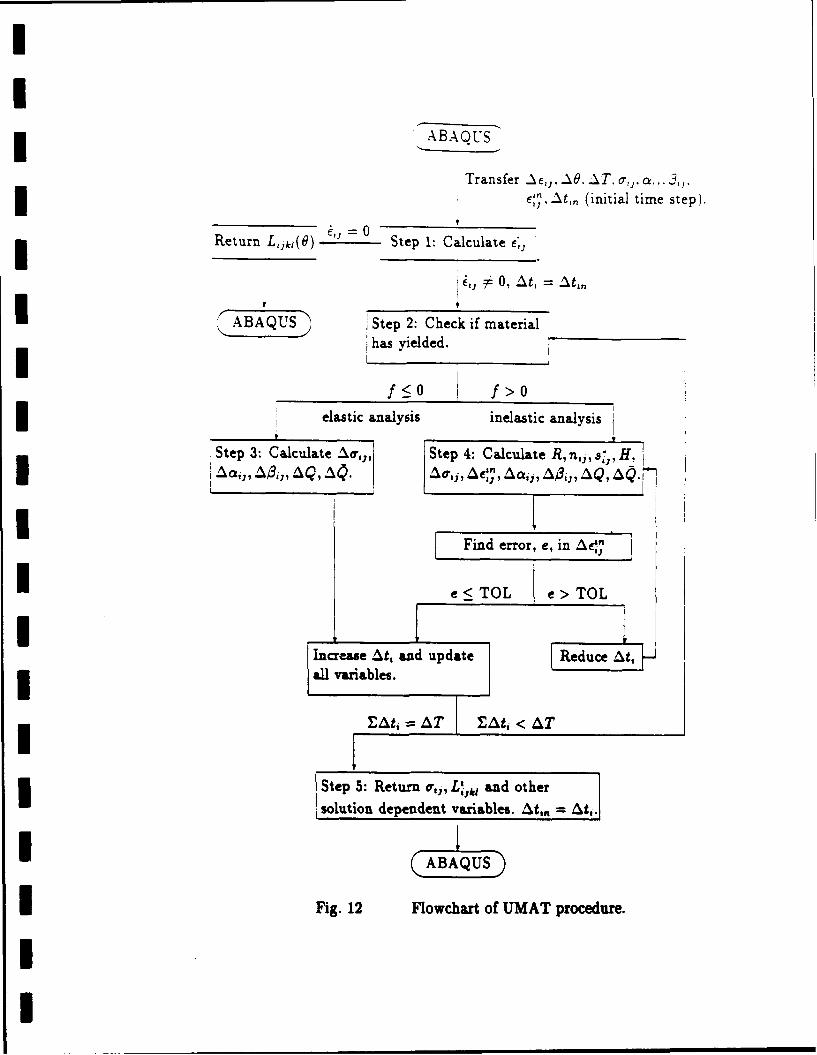
Figure 12 shows a flow chart for the computations performed by UMAT. The steps
involved are briefly explained below.
Step 1: ABAQUS passes to UMAT the increments of strain, temperature and time, the
current values of stress and other solution dependent variable and the initial time step for
local integration. From this information the strain rate is calculated. If the strain rate is
zero the current instantaneous stiffness is returned, this indicates the beginning of a step.
If the strain rate is non-zero then UMAT proceeds to perform the numerical integration.
Step2: The yield condition is checked, if it is not violated then an elastic analysis is
performed, Step 3, otherwise the inelastic equations are integrated Step 4.
. 3: Elastic analysis. The new stress and other solution dependent variables are
comxnuted, the time step, At, is increased, and all variables updated. Step 2 is repeated
14
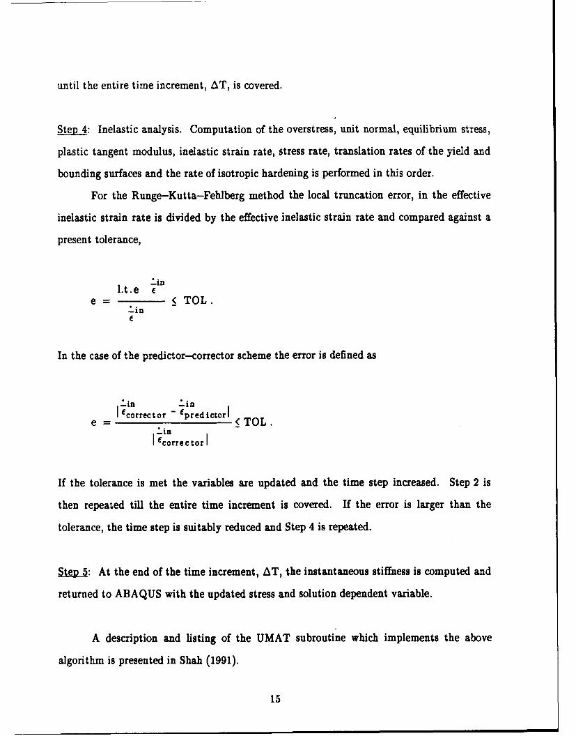
until the entire time increment, AT, is covered.
Step 4: Inelastic analysis. Computation of the overstress, unit normal, equilibrium stress,
plastic tangent modulus, inelastic strain rate, stress rate, translation rates of the yield and
bounding surfaces and the rate of isotropic hardening is performed in this order.
For the Runge-Kutta-Fehlberg method the local truncation error, in the effective
inelastic strain rate is divided by the effective inelastic strain rate and compared against a
present tolerance,
-in
L.t.e (e = ( TOL.
In the case of the predictor-corrector scheme the error is defined as
-in -inI fcorrector - Epredictor I TOL.
-inI correc torI
If the tolerance is met the variables are updated and the time step increased. Step 2 is
then repeated till the entire time increment is covered. If the error is larger than the
tolerance, the time step is suitably reduced and Step 4 is repeated.
SeR 5: At the end of the time increment, AT, the instantaneous stiffness is computed and
returned to ABAQUS with the updated stress and solution dependent variable.
A description and listing of the UMAT subroutine which implements the above
algorithm is presented in Shah (1991).
15

2.1.6 Numerical and Exverimental Results
The periodic array finite element model, together with the thermoviscoplastic
constitutive equations, were used to predict the rate dependent behavior of a unidirectional
SCS6/Ti-15-3 composite at high temperatures. Experimental data for comparison was
provided by Tuttle et al. (1990). Test specimens were manufactured by hot-pressing
Ti-15-3 foils between unidirectional tapes of silicon carbide fibers. The diameter of the
fibers was 0.14 mm, and the fiber volume content of the composite was 32 percent.
Material properties of titanium, for the numerical analysis, were evaluated by fitting
experimental data obtained at elevated temperatures from unreinforced specimens. These
neat matrix specimens were manufactured by the same process as the composite and so are
expected to represent the in situ properties of the matrix in the reinforced specimens. The
SCS6 fibers were found to remain elastic in the temperature range considered here. The
finite element mesh used for the analysis is shown in Fig. 1.
The first specimen was subjected to a multistep creep test at a temperature of
566' C. Loading was in the direction of the fiber. Figure 13 shows the loading history of
axial stress against time in hours. The specimen was allowed to creep at stress levels of
49 MPa, 97 MPa, 167 MPa and 262 MPa with hold time of 1.35, 1.42, 17.20 and 5.11 hours
respectively. The computed strain in the axial direction is compared to the experimental
record in Fig. 14. The onset of the creep strain is marked in the figure each stress level.
For each stress level, the axial strain computed immediately after application of the
sustained stress magnitude was drawn to match the strain found in the experiment. In this
way, any errors that might have accumulated during application of the overall stress have
been subtracted.
Almost no creep strain was measured at the lowest stress of 49 MPa. As expected,
both experiment and calculations show an increase in creep rate with increase in the overall
stress increment. In general, the numerical model predicted higher rates in the early stages
of each step compared to those measured experimentally, however the total creep strains in
I16
each step were comparable. Some noise in the experimental data appears in the figure and
is attributed to equipment limitations.
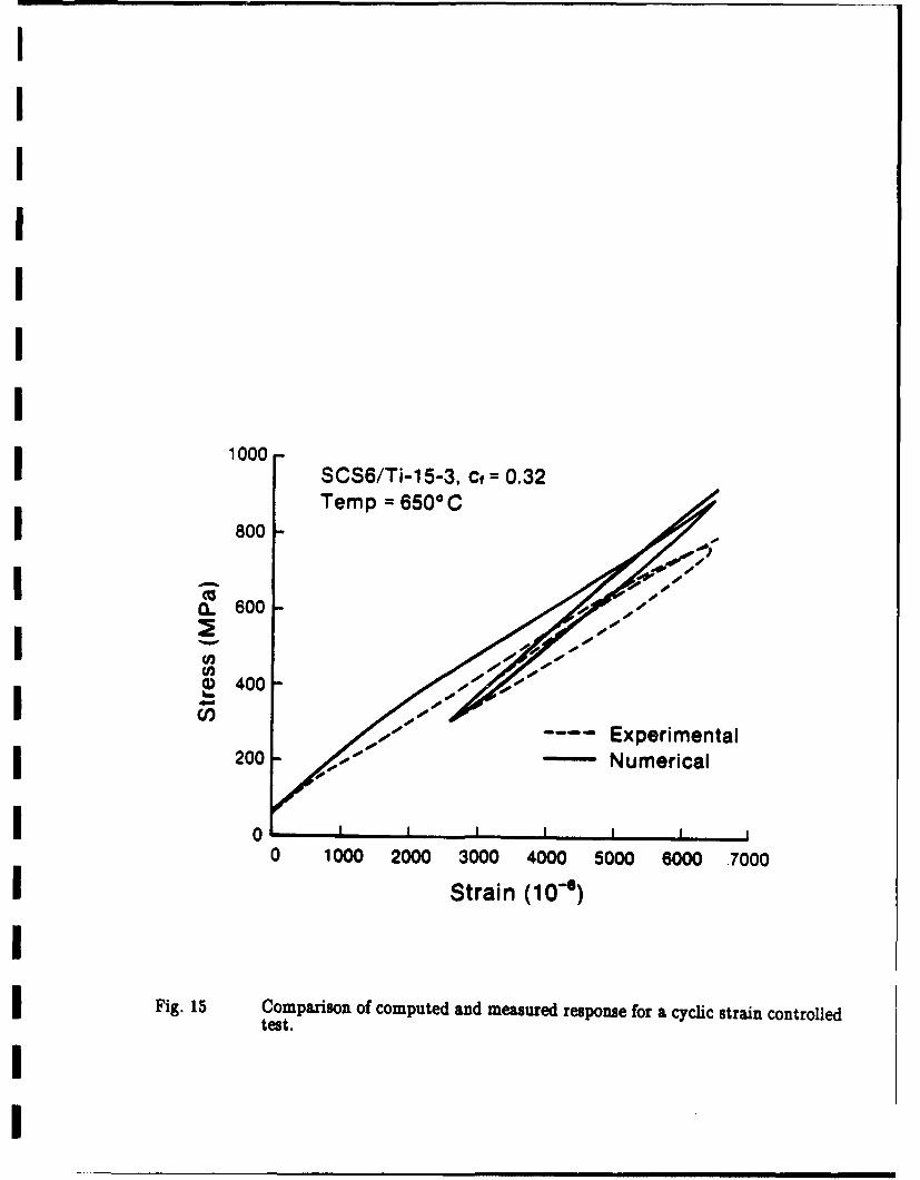
In the second experiment, a cyclic strain controlled test was performed at 650' C.
The specimen was loaded in the fiber direction at a rate of 10-4/sec to a total strain of
6500 x 10-6, unloaded at the same rate to 2600 x 10-6 and then reloaded at a higher rate of
10- 3/sec to 6500 x 10-6. A comparison of the measured and computed stress-strain
response is shown in Fig. 15. Qualitatively, there is a good agreement between the two,
however a stiffer response in predicted from the simulation. Both the experimental data
and calculations reach a higher stress at the end of the second cycle as compared to the
first, for the same strain level. This is obviously due to the increase in strain rate.
From the limited available experimental data, at elevated temperatures, for the
SCS6/Ti-15-3 composite system, it appears that the thermoviscoplastic composite model
developed here does predict the actual response fairly well.
2.2 Fatigue Damage in Metal Matrix Composites
Experiments suggest that cyclic loading of metal matrix composites may not lead to
fracture, but it results in a substantial reduction of laminate elastic stiffness depending on
the applied stress amplitude. The two major causes of stiffness reduction consist of matrix
cracks parallel to the fibers and matrix cracks transverse to the fibers. The observed loss of
stiffness associated with the matrix cracks transverse to the fibers. The observed loss of
stiffness associated with the matrix cracking in unidirectional B/Al composites and
laminates cycled under constant amplitude (Dvorak and Johnson 1980) indicates that
damage develops only if the load amplitude reaches a certain magnitude in a given
laminate, and that the stiffness loss terminates in a saturation damage stat after a certain
number of cycles.
17

Our research developed a failure damage theory with regard to the aforementioned
experimental observations. The model recognizes the relation between cyclic plastic
straining and damage growth in metal matrix composites, which was described in our
previous work (Dvorak and Wung 1988), and focuses on evaluation of the type and extent
of damage in individual plies of the laminate, required to reach a shakedown state under a
prescribed program of variable cyclic loading. Our choice of micromechanical models is
motivated, in part, by experimental observations of the crack systems in individual plies of
fatigued laminates. Of course, a detailed description of the actual damage geometry would
be quite difficult. Instead, for modeling purposes, the mode of damage that is expected to
develop in a given ply is derived from a bimodal damage theory that identifies crack
systems associated with the fiber-dominated (FDM) or matrix-dominated (MDM) modes
of the analogous bimodal plasticity theory of plastic deformation of fibrous plies, proposed
by Dvorak and Bahei-E1-Din (1987). An examination of the plastic straining and crack
growth processes leads to the conclusion that the actual saturation damage state
corresponds to a minimum amount of damage required for shakedown of the laminate.
Appropriate crack density measure are introduced, and the total crack density in the
laminate is identified with an objective function that is minimized with an optimization
scheme that involves physically based nonlinear constraints in a general loading domain
(Dvorak, Lagoudas and Huang 1990b). The analysis evaluates stiffness changes in the
saturation state and also yields estimates of the average stresses in fibers of the damaged
composite.
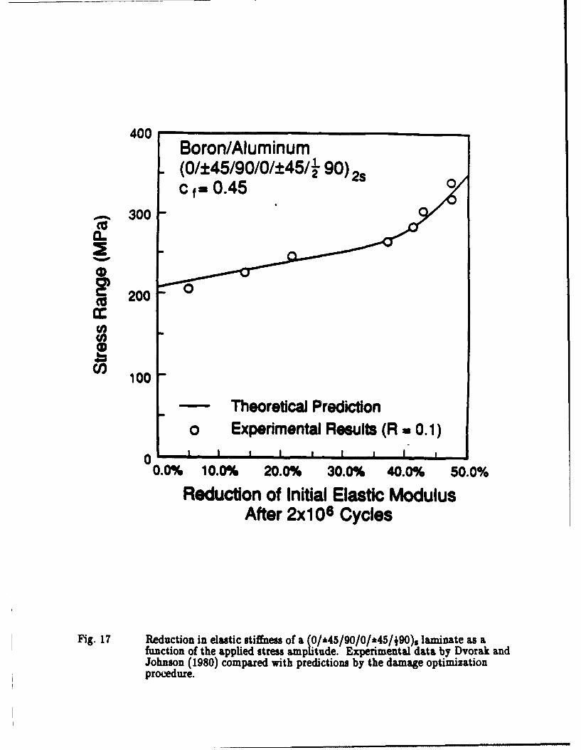
A comparison of the theoretical predictions indicated by the present optimization
procedure, with experiments conducted by Dvorak and Johnson (1980) is given in Fig. 16
for a (0/90)2 laminate and in Fig. 17 for a (0/*45/90/0/*45/A90)2 s laminate. The
correlation is quite good for the whole range of stress amplitudes applied in the
optimization scheme, as it can be seen from the figures. We note that the optimization
scheme may be come unstable if the applied stress amplitude becomes too large. Moreover,
18

the analysis itself may not be applicable if the maximum stress approaches about 90% of
the endurance limit, due to the experimentally detected frequency of fiber breaks.
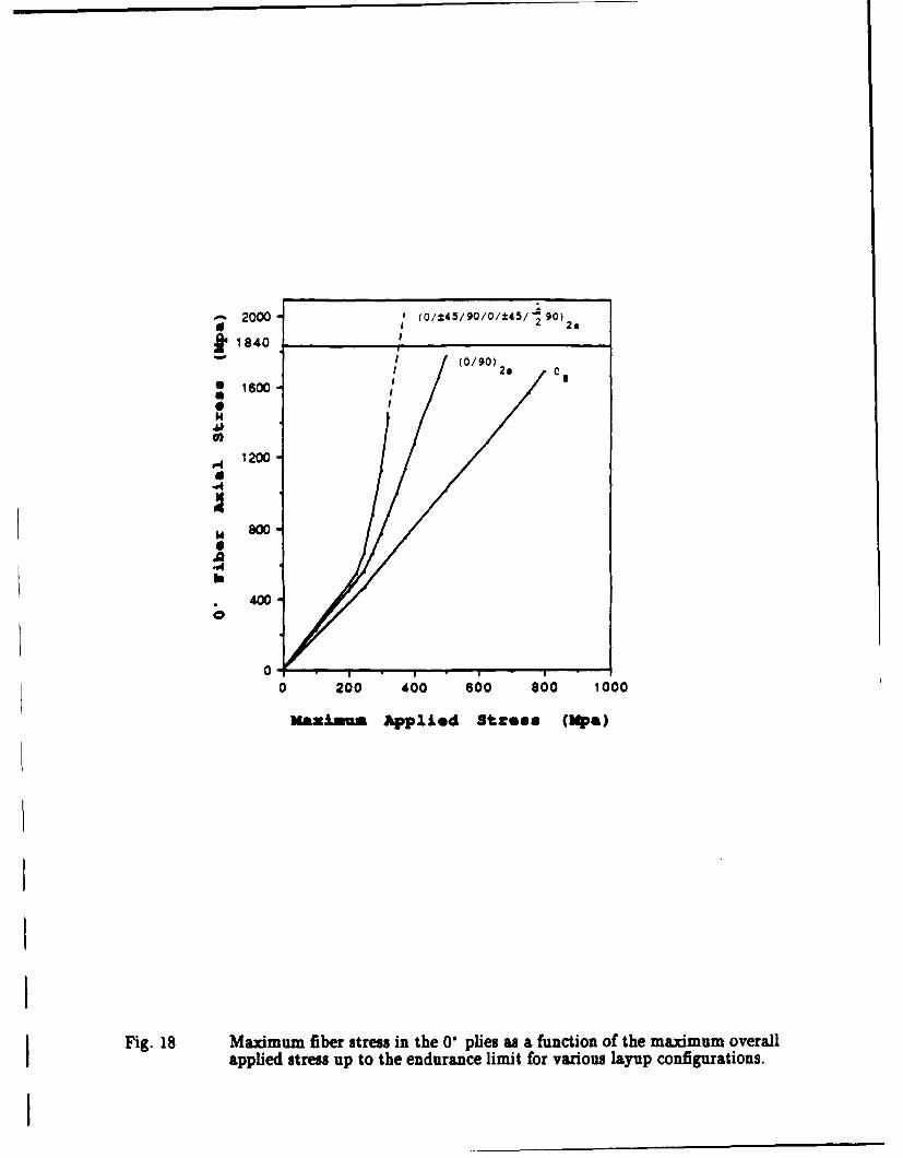
As the composite's endurance limit is approached, damage development in the
matrix almost unloads completely the matrix and transfers the applied loading to the
fibers. The composite will eventually fail when the endurance limit of the fibers in the 0"
plies as a function of the maximum applied overall stress for the (0/90)s,
(0/*45/90/0/*45/90)2s laminates and a 08 unidirectional in Fig. 18. The maximum
applied stress ranges from zero up to the endurance limit of the laminate as reported by
Dvorak and Johnson (1980) (the endurance limit of the Os is taken to be 800 MPa, of the
(0/90)2s is 500 MPa and of the (0/*45/90/0/*45/190)2S laminate indicates extrapolation
from the last computed point that corresponds to 325 MPa. Taking into consideration the
scattering in the experimental data for the endurance limit of the various laminates, the
maximum fiber stress (fiber endurance limit) may be approximated by the average of the
maximum fiber stresses in the three cases of Fig. 18.
19

3. EXPERIMENTAL WORK
3.1 Equipment
Under partial support from this grant, we have acquired a new high temperature
testing facility for biaxial loading of composite thin-walled tube specimens. Mechanical
loads are applied by a MTS axial-torsion servohydraulic machine. The maximum loads
are * 225 KN axial, and 2.8 KN-m in torsion. An IBM 386 microcomputer is connected to
the testing system for data acquisition and load control.
Test temperatures are provided and controlled by a resistive furnace manufactured
by CM Furnaces, Inc. This is a vertical tube furnace which splits open along a vertical
axis to wrap around the specimen. The unit consists of three independent heating zones
placed on top of each other. The center zone is 2" long and the top and bottom zones are
each 1" long. The resistive heaters are made of platinum rhodium 60/40 0.020" diameter
wire. The inner diameter of the furnace is 2" and the outer diameter about 10" which
enables the furnace to be accommodated in the existing MTS machine frame. The overall
height of the furnace is approximately 6". The maximum operating temperature of the
furnace is 1400" C. The temperature gradient along the length of the center zone, where
the strain measurements are usually made, was evaluated by heating a steel tube with
thermocouples connected to its inner and outer surfaces. At 1000" C, the temperature in
the gage area was 1000 * 2" C.
Strain measurements are made with a biaxial MTS extensometer. The
extensometer is water cooled and can be used in conjunction with quartz connecting rods
which make it possible to operate at 1000 C or with ceramic rods that can operate at
1200" C. The extensometer rod ends contact single points on the tubular specimen wall and
pivot on them to measure extension and rotation. The contact points require small
dimples be imprinted on the specimen to avoid any slippage during test. To prevent
20

damaging the composite specimen, the required dimples will be imprinted on small tabs
made of ceramic cement and affixed to the specimen. The gage length of the extensometer
is 1" and the operating ranges are * 0.1" in the axial direction and * 5° in the torsional
direction. However, the maximum windup at the contact points is * 100 which dictates on
the torsional range which we can measure with our tubular specimen. The strain ranges
computed from the above values are * 10% for the normal strain in the axial direction, and
* 1.5% for the longitudinal shear strain.
3.2 Specimens
The composite system selected for this project is a nickel base Waspaloy matrix
reinforced by GE 218 tungsten wire. This system was selected based on experience gained
during fabrication of flat specimens of the same system by Westinghouse. Last year, we
contracted Westinghouse for fabrication of thin wall tubular specimens for this project.
Fiber volume fraction was specified as 0.35 and the number of plies as 5. The specimen
diameter (1.25") and length (15") were selected to conform with the equipment described
above and with gripping outside the furnace. Delivery of the specimen was delayed several
times due to inability of General Electric to provide 3D tungsten wire, and due to the lack
of a standard procedure for making superalloy matrix composite tubes. The tubes were
finally delivered in early 1992. The report by Blankenship (1992) in the enclosure describes
the manufacturing procedure. The tubes will be tested under the forthcoming AFOSR
grant, in the summer-fall period of 1992.
ACKNOWLEDGMENT
This work was monitored by Lt. Col. George Haritos and Dr. Walter Jones, who
provided encouragement and useful technical suggestions.
21
!
REFERENCES
Blankenship, W.P. and Przywaarty, F.L., (1992), "Fabrication of Metal Matrix CompositeTubes for Rensselaer Polytechnic Institute," Report by Westinghouse Electric Corporation,Advanced Energy Systems Department, Pittsburgh, PA
Burden, R.L. and Faires, J.D., (1985), Numerical Analysis, third edition, Prindle, Weberand Schmidt Publishers, Boston.
Dafalias, Y.F. and Popov, E.P., (1976), "Plastic Internal Variable Formalism of CyclicPlasticity," ASME J. Appl. Mech., Vol. 43, p. 645.
Dvorak, G.J. and Johnson, W.S., (1980), "Fatigue of Metal Matrix Composites," Int. J. ofFracture, Vol. 16, p. 585.
Dvorak, G.J., (1983), "Metal Matrix Composites: Plasticity and Fatigue," in Mechanics ofComposite Materials: Recent Advances, Z. Hashin and C.T. Herakovich, editors,Pergamon Press, pp. 73-91.
Dvorak, G.J. and Teply, J.L., (1985), "Periodic Hexagonal A rray Models for Plasticity ofComposite Materials," Plasticity Today: Modeling, Methods and Application, W. OlszakMemorial Vol., A. Sawczuk and V. Blanchi, Eeitors, Elsevier, p. 623.
Dvorak, G.J., (1986), "Thermal Expansion of Elastic-Plastic Composite Materials," J.Appl. Mech., Vol. 53, pp. 737-743.
Dvorak, G.J., (1937), "Thermomechanical Deformation and Coupling in Elastic-PlasticComposite Materials," in Thermomechanical Couplings in Solids, H.D. Bui, andQ.S. Nguyen, editors, North-Holland, pp. 43-54.
Dvorak, G.J. and Bahei-El-Din, Y.A., (1987), "A Bimodal Plasticity Theory of FibrousComposite Materials," Acta Mechanica, Vol. 69, p. 219.
Dvorak, G.J., Bahei-El-Din, Y.A., Macheret, Y., and Liu, C.H., (1988), "AnExperimental Study of Elastic-Plastic Behavior of a Fibrous Boron-AluminumComposite," J. Mech. Phys. Solids, Vol. 36, p. 655.
Dvorak, G.J. and Wung, E.C.J., 1988), "Fatigue Damage Mechanics of Metal MatrixComposite Laminates," in Strain Localization and Size Effect Due to Cracking andDamage, J. Mazars and Z.P. Bazant, eds., Elsevier, London.
I Dvorak, G.J., (1990) "On Uniform Fields in Heterogeneous Media," Proceedings of theRoyal Society, London, A 431, pp. 89-110.
I Dvorak, G.J. Bahei-El-Din, Y.A., Shah, R.S., Nigam, H., (1990), "Experiments andModeling in Plasticity of Fibrous Composites," in Inelastic Deformation of CompositeMaterials, G.J. Dvorak, editor, Springer-Verlag, New York, Inc., pp. 270-293.
Dvorak, G.J., Lagoudas, D. and C. Huang, (1990), "Fatigue Damage of Metal MatrixComposites: Optimization and Shakedown Analysis," AMD - Vol. 11/MD - Vol. 22,I American Society of Mechanical Engineers, New York, pp. 41-54.
I 22
I
I Dvorak, G.J., (1991), "Plasticity Theories for Fibrous Composite Materials," Metal MatrixComposites, Vol. 2, R.K. Everett and R.J. Arsenault, Editors, Academic Press, Boston,pp. 1-77.
Dvorak, G.J., (1992b), "Transformation Field Analysis of Inelastic Composite Materials,"Proceedings of the Royal Society, London, A437, pp. 311-327.
Dvorak, G.J. and Benveniste, Y., (1992a), "On Transformation Strains and Uniform Fieldsin Multiphase Elastic Media, Proceedings of the Royal Society, London, A 437,pp. 291-310.
Eisenberg, M.A., and Yen, C.F., (1981), "A Theory of Multiaxial AnisotropicViscoplasticity," ASME J. Appl. Mech., Vol. 48, p. 276.
Hall, R., (1990), Ph.D. Dissertation, Rensselaer Polytechnic Institute.Kumar, V., Morjaria, M. and Mukherjee, S., (1980) "Numerical Integration of Some Stiff
Constitutive Models of Inelastic Deformation," J. Eng. Matls. Tech., v. 102, pp. 92-96.
Shah, R.S., Bahei-EI-Din, Y.A., and Dvorak, G.J., (1990 , "A Numerical Study of theRate-Dependent Behavior of High Temperature Fibrous omposite Systems," IUTAMSymposium on Inelastic Deformations of Composite Materials, Rensselaer PolytechnicInstitute.
Shah, R.S., (1991), "Modeling and Analysis of High-Temperature Inelastic Deformation inMetal-Matrix Composites," Ph.D. Thesis, Rensselaer Polytechnic Institute.
Teply, J.L. and Dvorak, G.J., (1988), "Bounds on Overall Instantaneous Properties ofElastic-Plastic Composites," J. Mech. Phys. Solids, Vol. 36, p. 29.
I Tuttle, M., Rogacki, J. and Johnson, W.S., (1990), Private Communication.
IIIIIII* 23

II
Table 1 Parameters used in prediction of Ti-15-3 behavior
I Material Units 27" C 482" C 649" C
Property
E GPa 92.4 72.2 55.0
V 0.351 0.351 0.351
Y MPa 810 250 52.5
Ho MPa 1400 60 50
I h GPa 40 90 52
Y MPa 930 870 278
p 9.95 2.45 1.43
k (MPa)'P/s 7.6x10⁻²⁰ 4.2x10 -7 3.2x10⁻⁶
Qa MPa -120 -220 -30
Qa MPa 50 1700 95
q 920 7.5 2.61
I q 920 7.5 2.61
mr 1.2 1.29 1.35
Cr (MPa)mrs 1.OxlO-4 7.0xj0-4 2.OxlO-4
Cr (MPa) -r)s 1.OxlO-4 7.0x10⁻⁴ 2.0x104
III
* 24

I
FIGURES
Fig. 1 Finite element subdivisions of the PHA representative volume element.
Fig. 2 Examples of bimodal yield surfaces.
Fig. 3 Schematic of equilibrium yield surface and bounding surface in the stressspace of an elastically isotropic material.
Fig. 4 Comparison of measured and computed response of a Ti-15--3 specimen atroom temperature and stress rate of 2.6 MPa/s.
Fig. 5 Comparison of measured and computed response of a Ti-15-3 specimen at482" C and stress rate of 2.6 MPa/s.
Fig. 6 Comparison of measured and computed response of a Ti-15-3 specimen at649" C and stress rate of 2.6 MPafs.
Fig. 7 Comparison of measured and computed response of a Ti-15-3 specimen atroom temperature and strain rate of 10-4/s.
Fig. 8 Comparison of measured and computed response of a Ti-15-3 specimen at482" C and strain rate of 10-4/s.
Fig. 9 Comparison of measured and computed response of a Ti-15-3 specimen at649" C and strain rate of 10-4/8.
Fig. 10 Flowchart of global iteration scheme for the ABAQUS finite elementprogram.
Fig. 11 Newton-Raphson procedure for global iteration.
Fig. 12 Flowchart of UMAT procedure.
Fig. 13 Stress history applied in multistep creep test of a SCS6/Ti-15-3 composite.
Fig. 14 Comparison of computed and measured strain found in a multistep creep teston a SCS6/Ti-15-3 composite.
Fig. 15 Comparison of computed and measured response for a cyclic strain controlledtest.
Fig. 16 Reduction in elastic stiffness of a (0/90)s laminate as a function of appliedstress amplitude. Experimental data by Dvorak and Johnson (1980)compared with predictions by the damage optimization procedure.
Fig. 17 Reduction in elastic stiffness of a (0/i45/90/0/ 45/190)s laminate as afunction of the applied stress amplitude. Experimental data by Dvorak andJohnson (1980) compared with predictions by the damage optimization
* procedure.
Fig. 18 Maximum fiber stress in the 0* plies as a function of the maximum overallapplied stress up to the endurance limit for various layup configurations.
25
0
CVa)
CYa)
Cm.
I ~MDM (SCM)FDM (VOIGT) X2
B: B-Al, cf = 0.5G: Gr-AI, cf =0.5 X1
NB2 -B
I 70' -- V- -N
-8 -6 - -2 \.4 ~ 2' 4~ 6
* -4
I 4-
2 N Bj~/------- BN
-8 - -~b4 0 2 .~~ 6 8
-2
Fig. 2 Examples of bimodal yield surfaces.

fsaq f(s4,3uK0 )= n
Fig. 3 Schematic of equilibrium yield surface and bounding surface in the stressspace of an elastically isotropic material.

d 0
.0.
c;
C4
c0.
Cvciyy SS3&
0
00,
0
IW0 0 C
18
.bb
(*0Sma±s

oc
w
0
(VN S:&
cc
-4
I ID
00*1o..
a 0i
I z.
-i
I~~~ ~ I0 I= 1 1 I-
0 cis
Sc 085.
S.8
NUNSS381S

o Io
0.
0 Z
os
0o C
00
(VdO)SS3HIS

co
r.
00
90
0 4~
- 0.
zd SMUL

START
Step 1: Input material properties. loading.
history, initial time increment for globaliteration, initial time step for localintegration and total time Ttt.
Step 3: Assemble global stiffness. Compute nodaldisplacements AUk, corresponding to applied nodal
. forces AFk, in time increment AT,. Calculate
strain increment at integration points, _
Step 4: At each integration point call UMAT tocompute the stress increment from ,e, and the
instantaneous stiffness at the end of AT,.
Calculate the off-balance Compute strainsnodal forces AFk from the Ak > TOLG corresponding tot corspndn todstress increments returned to AFk and addby UMAT. I them to AE'.
Ai k < TOL G
E AT, < T t
E ZAT, =T'o'
Fig. 10 Flowchart of global iteration scheme for the ABAQUS finite elementprogram.

IFPI
ITLAI6 ----
AUIUIU
Fi.I etnRpsnpoedr o lblieain
I
AB AOQUS
Transfer A. A0. AT. o. a... 3.e,". At,, (initial time step).
Return L1 k(O) 0 Step 1: Calculate e*,
I,# 0, At, =At,
IABAU Step 2: Check if materialhas yielded.
f :50 f>O0
elastic analysis inelastic analysis
Step 3: Calculate Ac',,, Step 4: Calculate R, n,_,, ,, H,At', Ao3,,, AQ, AQ. A,,, , A, 3,, AQ, AQ.
Find error, e, in Ae
I e<TOL e >TOL
Increase At, and update Reduce At,I all variables.
EAt,=AT ,At,<AT
I Step 5: Return o,, L~ekl and othersolution dependent variables. At,. = At ,.
ABQUI Fig. 12 Flowchart of UMAT procedure.
II

30IC6Ti153
I 300
250150
200- r
a) 100 5I01 2 5 3
Tim Ihs
F. 1 00teshsoyapidinmlitpcepts f C6T-53cmoie

1500 -SCS6/Ti-15-3, cf = 0.32Multistep Creep [ .T-'
I!
8 = 566 ° C T-
I ' -,,.262 MPa1000
I"
I < 5° / ' 167 MPa ... Experimental
/~ M . ...--- Numerical10 S I 3 0MP249 2MPM
1~0
I 1Time (hrs)
IFig. 14 Comparison of computed and measured strain found in a multistep creep teston a SCS6/Ti-15-3 composite.
I ueia
I
.0 .1
0 00 .0
2 00 Nueia
0- 6001-__-
0 1000 2000 3000 4000 5000 6000 .7000
I Strain (10-e)
IFig. 15 Comparison of computed and measured response for a cyclic strain controlled
tet

600Boron/Aluminum(0/90) 2s
500 cf= 0.4 5
(m 400
0
(a0
0200
100 - Theoretical Prediction
o Experimental Results (R = 0.1)
0.0% 10.0% 20.0% 30.0% 40.0% 50.0% 60.0%
Reduction of Initial Elastic ModulusAfter 2x10⁶ Cycles
Fig. 16 Reduction in elastic stiffness of a (0/90)s laminate as a function of applied
stress amplitude. Experimental data by Dvorak and Johnson (1980)compared with predictions by the damage optimization procedure.
400Boron/Aluminum(0/±45/90/0/±45/ 90) 2sc fnO0. 4 5
0, 300
200
cc
100
Theoretical Predictiono Experimental Results (R =0. 1)
00.0% 10.0% 20.0% 30.0% 40.0% 50.0%
Reduction of Initial Elastic ModulusAfter 2x10 s Cycles
Fig. 17 Reduction in elastic stiffness of a (0/*45/90/0/*45/190)s laminate as afunction of the applied stress amplitude. Experimental data by Dvorak andJohnson (1980) compared with predictions by the damage optimizationprocedure.
2000 (0/t45/9010/±45/ 90)2s
k 1840 I
(0/90)2
* 1600 I 8
1200
.e4
4 00,0oA
0' I I
0 200 400 600 800 1000
baziimuu Applied stress (lip&)
Fig. 18 Maximum fiber stress in the 0" plies as a function of the maximum overallapplied stress up to the endurance limit for various layup configurations.
LIST OF PUBLICATIONS
G.J. Dvorak and E.C.J. Wung, (1988), "Fatigue Damage Mechanics of Metal MatrixComposite Laminates," Cracking and Damage Strain Localization and Size Effect, ed.,J. Mazars and Z.P. Bazant, Elsevier Applied Science Publishers Limited, London.
G.J. Dvorak, D. Lagoudas and C. Huang, (1990), "Fatigue Damage of Metal MatrixComposites: Optimization and Shakedown Analysis," AMD - Vol. 111/MD - Vol. 22,American Society of Mechanical Engineers, New York, pp. 41-54.
G.J. Dvorak, (1990), "On Uniform Fields in Heterogeneous Media," Proc. Royal Soc.London, A 431, pp. 89-110.
Y. Benveniste and G.J. Dvorak, (1992), "On a Correspondence Between Mechanical andThermal Fields in Composites with Slipping Interfaces," Inelastic Deformation ofComposite Materials, G.J. Dvorak, Ed., Springer-Verlag, New York, pp. 75-91.
Y. Benveniste, G.J. Dvorak and T. Chen, (1991), "On Diagonal and Elastic Symmetry ofthe Approximate Effective Stiffness Tensor of Heterogeneous Media," Journal of theMechanics and Physics of Solids, pp. 927-946.
G.J. Dvorak, (1991), "On Thermal Hardening and Uniform Fields in Two-phaseComposite Materials," in Anisotrouv and Localization of Plastic Deformation, ed. byJ-P. Boehler and A. Khan, Elsevier Applied Science, London, pp. 19-22.
Y.A. Bahei-El-Din, R.S. Shah and G.J. Dvorak, (1991), "Numerical Analysis of theRate-Dependent Behavior of High Temperature Fibrous Composites," AMD-Vol. 118,Mechanics of Composites at Elevated and Cryogenic Temveratures, edited by S.N. Singhal,W.F. Jones and C.T. Herakovich, pp. 67-78.
Y.A. Bahei-EI-Din and G.J. Dvorak, (1991), "Local Fields in Uncoated and Coated HighTemperature Fibrous Composite Systems," AD-Vol. 25-2. Damage and OxidationProtection in High Temperatue Comvosites - Vol. 2, ASME, pp. 21-34.
G.J. Dvorak, T. Chen and J. Teply (1992), "Thermomechanical Stress Fields inHigh-Temperature Fibrous Composites: I. Unidirectional Laminates," Composite Scienceand Technology, Vol. 43, pp. 347-358.
G.J. Dvorak, T. Chen and J. Teply (1992), "Thermomechanical Stress Fields inHigh-Temperature Fibrous Composites: II. Laminated Plates," Composite Science andTechnology, Vol. 43, pp. 359-368.
G.J. Dvorak and Y. Benveniste, (1992), "On the Thermomechanics of Composites withImperfectly Bonded Interfaces and Damage," to appear in International Journal of Solidsand Structures.
44

LIST OF PRESENTATIONS
Presentations by Dr. Dvorak
ASME/WAM, "On a Correspondence Between Mechanical and Thermal Effects inTwo-Phase Composites," San Francisco, CA, December 10-15, 1989.
Invited Lecture, Department of Applied Mechanics and Engineering Science, University ofCalifornia, San Diego, March 5, 1990.
Short Course on "Metal Matrix Composites," (program co-director and lecturer), UCLA,March 6-8, 1990.
Invited Lecture, University of Dlinois-Chicago, April 25, 1990.
Invited Lecture, Northwestern University, April 26, 1990.
IUTAM Symposium on Inelastic Deformation of Composite Materials, "SomeExperimental Results in Plasticity of Fibrous Composites," Rensselaer PolytechnicInstitute, Troy, NY, May 29-June 1, 1990.
United Technologies Engineering Coordination Activities Conference, "Fracture of FibrousComposites," Stamford, Connecticut, May 14-18, 1990 (presented by J. Zarzour).
IST-SDIO/ONR Woods Hole IV Research Review, "Local Stresses in High TemperatureComposites and Laminates," Woods Hole, Massachusetts, June 4, 1990.
I Invited Lectures, Politecnico di Milan, Milan, Italy, June 11-12, 1990.
Invited Lecture, EniChem, Milan, Italy, June 13, 1990.
Invited Lecture, Institute of Theoretical and Applied Mechanics, Czechoslovak Academy ofSciences, Prague, Czechoslovakia, June 25, 1990.
Short Course on "Advanced Composite Materials and Structures," RPI, July 24, 1990.
KAPL corporate visit, RPI, August 3, 1990
Grumman Aircraft visit, RPI, August 8, 1990.
ASME/WAM, "On Uniform Fields in Heterogeneous Media," Dallas, Texas, November 27,1990.
ASME/WAM, "Fatiue Damage of Metal Matrix Composites: Optimization andShakedown Analysis,' Dallas, Texas, November 27, 1990.
AFOSR, "Deformation and Damage Mechanisms in High Temperature Composites withDuctile Matrices," Bolling AFB, D.C., March 15, 1991.
AFOSR, "Static and Fatigue Damage in High Temperature Composites," Boiling AFB,D.C., March 15, 1991.
45U

Presentations by Dr. Dvorak (continued)
DARPA HiTASC Program Review, "Thermomechanical Compatibility in HighTemperature Composites," March 27, 1991.
First U.S. National Congress on Computational Mechanics, "A New Approach in NonlinearMicromechanical Analysis of Heterogeneous Media," (with Y.A. Bahei-El-Din and A.M.Wafa), Chicago, Illinois, July 1991.
Invited Lecture at Plasticity '91 at The Third International Symposium of Plasticity andits Current Applications, Grenoble, France, August 12-16, 1991.
Invited Lecture in the Klokner Institute of the Czech Technical University in Prague,"Engineering Education in the United States," Czechoslovakia, August 29, 1991.
Invited Lecture at conference on "New Trends in Structural Mechanics," Institute ofTheoretical Applied Mechanics, "Fatigue Damage and Shakedown in Metal MatrixComposite Laminates," Czechoslovak Academy of Science, Prague, September 2, 1991.
American Society of Composites Meeting, "Experimental Evaluation of Yield Surfaces andPlastic Strains in a Metal Matrix Composite," Albany, NY, October 6-9, 1991.
28th Annual Technical Meeting of the Society of Engineering Science, "Fatigue andShakedown in Metal Matrix Composites," Gainesville, Florida, November 6-8, 1991.
Invited Lecture ASME/WAM, "On Some Exact Results in Thermoplasticity of CompositeMaterial," Atlanta, GA, December 4, 1991.
Invited Lecture ASME/WAM, "Thermal Stresses in Elastic-Plastic Composites withCoated Fibers," Atlanta, GA, December 6, 1991.
Presentations by Dr. Bahei-El-Din
Invited Lecture, Mechanics of Materials Branch, NASA Langley Research Center,Hampton, VA, October 27, 1989.
Third Symposium on Composite Materials: Fatigue and Fracture, American Society forTesting and Materials, "Fracture of Fibrous Metal Matrix Composites ContainingDiscontinuities," Lake Buena Vista, FL, November 6-7, 1989.
Invited Lecture, Theoretical and Applied Mechanics Department, Cornell University,Ithaca, NY, April 25, 1990.
Invited Lecture, Mechanics of Materials Branch, NASA Langley Research Center,Hampton, VA, September 26, 1990.
AFOSR Program Review, Lt. Col. George Haritos, monitor, Rensselaer PolytechnicInstitute, Troy, New York, December 12, 1990.
High Temperature Advanced Structural Composites Program, ONR/DARPA-HiTASC,Rensselaer Polytechnic Institute, Troy, New York, March 8, 1991.
* 46

IAFOSR Program Review, Lt. Col. Steve Boyce, monitor, Directorate of Aerospace Science,Air Force Office of Scientific Research, Boiling Air Force Base, District of Columbia,March 15, 1991.
Symposium on the Mechanics of Composites at Elevated and Cryogenic Temperatures,ASME Applied Mechanics Division Meeting, Columbus, Ohio, June 16-19, 1991 (twopresentations).
First U.S. National Congress on Computational Mechanics, on "Local Stresses in HighTemperature Fibrous Composites," Chicago, Illinois, July 21-24, 1991 (two presentations).
Invited Lecture, Mechanics of Materials Branch, NASA Langley Research Center,Hampton, Virginia, January 21, 1992.
Invited Lecture, Aluminum Company of America, Alcoa Technical Center, Pennsylvania,January 22, 1992.
47

LIST OF PROFESSIONAL PERSONNEL
Dr. G.J. Dvorak - Principal InvestigatorDr. Y.A. Bahei-El-Din - Research Assistant ProfessorDr. H. Nigam - Research AssociateMr. R.S. Shah - Graduate Student
48
APPENDIX
Fabrication of Metal Matrix Composite Tubes
for
Rensselaer Polytechnic Institute
Fabrication of Metal Matrix Composite Tubesfor
Rensselaer Polytechnic Institute
February 1992
I
W. P. Blankenship
F. L. Przywarty
I
IWesinghousext Elr Corratim
Advacd EneFqy Systes DepuamaP.O. Bat 10664, Pittsbuh. PA 15236-0864
II
Ii
I FABRICATION OF METAL MATRIX COMPOSITE TUBES FOR
RENSSELAER POLYTECHNIC INSTITUTE
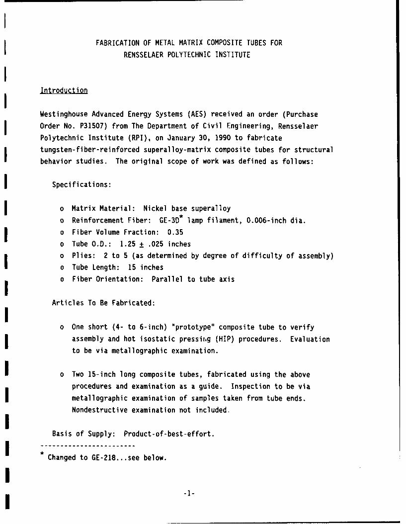
IIntroductionIWestinghouse Advanced Energy Systems (AES) received an order (Purchase
I Order No. P31507) from The Department of Civil Engineering, Rensselaer
Polytechnic Institute (RPI), on January 30, 1990 to fabricate
tungsten-fiber-reinforced superalloy-matrix composite tubes for structural
behavior studies. The original scope of work was defined as follows:
I Specifications:
o Matrix Material: Nickel base superalloy
o Reinforcement Fiber: GE-3D* lamp filament, 0.006-inch dia.
o Fiber Volume Fraction: 0.35
o Tube O.D.: 1.25 + .025 inches
o Plies: 2 to 5 (as determined by degree of difficulty of assembly)
o Tube Length: 15 inches
o Fiber Orientation: Parallel to tube axis
Articles To Be Fabricated:
o One short (4- to 6-inch) "prototype" composite tube to verify
assembly and hot isostatic pressih~g (HIP) procedures. Evaluation
to be via metallographic examination.
o Two 15-inch long composite tubes, fabricated using the above
procedures and examination as a guide. Inspection to be via
metallographic examination of samples taken from tube ends.
Nondestructive examination not included.
Basis of Supply: Product-of-best-effort.
Changed to GE-218... see below.
II -1-
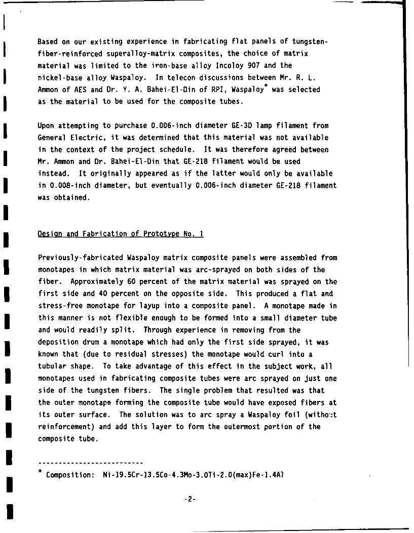
Based on our existing experience in fabricating flat panels of tungsten-
fiber-reinforced superalloy-matrix composites, the choice of matrix
material was limited to the iron-base alloy Incoloy 907 and the
nickel-base alloy Waspaloy. In telecon discussions between Mr. R. L.
Ammon of AES and Dr. Y. A. Bahei-El-Din of RPI, Waspaloy* was selected
as the material to be used for the composite tubes.
Upon attempting to purchase 0.006-inch diameter GE-3D lamp filament from
General Electric, it was determined that this material was not available
in the context of the project schedule. It was therefore agreed between
Mr. Ammon and Dr. Bahei-El-Din that GE-218 filament would be used
instead. It originally appeared as if the latter would only be available
in 0.008-inch diameter, but eventually 0.006-inch diameter GE-218 filament
was obtained.
Design and Fabrication of Prototype No. 1
Previously-fabricated Waspaloy matrix composite panels were assembled from
monotapes in which matrix material was arc-sprayed on both sides of the
fiber. Approximately 60 percent of the matrix material was sprayed on the
I first side and 40 percent on the opposite side. This produced a flat and
stress-free monotape for layup into a composite panel. A monotape made in
this manner is not flexible enough to be formed into a small diameter tube
and would readily split. Through experience in removing from the
i deposition drum a monotape which had only the first side sprayed, it was
known that (due to residual stresses) the monotape would curl into a
tubular shape. To take advantage of this effect in the subject work, all
monotapes used in fabricating composite tubes were arc sprayed on just one
side of the tungsten fibers. The single problem that resulted was that
the outer monotape forming the composite tube would have exposed fibers at
its outer surface. The solution was to arc spray a Waspaloy foil (witho t
reinforcement) and add this layer to form the outermost portion of the
composite tube.
I Composition: Ni-19.5Cr-13.5Co-4.3Mo-3.OTi-2.0(max)Fe-1.4Al
-2-I

The proposed approach to fabricating the composite tubes was to build an
assembly of concentric monotape and foil layers, encapsulate this assembly
in a hermetically sealed annular package bounded by inner and outer
stainless steel pipes or tubes, evacuate and seal off the package via an
evacuation tube, and consolidate the assembly by hot isostatic pressing
(HIP). To verify the adequacy of the detailed assembly method and HIP
consolidation cycle, a sublength composite tube designated Prototype No. 1
was fabricated.
The first step in this fabrication was the production of monotapes and
foils. To produce a monotape, the reinforcing fiber was wrapped at the
required pitch on a 16-inch diameter x 20-inch long aluminum drum which
was mounted in a custom-built wire wrapping lathe. Appropriate tension
for the given reinforcing wire diameter was maintained by an electrically
controlled clutch. Prior to wrapping, a release agent was applied to the
drum surface to prevent adherence of arc-sprayed metal. A monotape of 35volume percent reinforcement using 0.006-inch diameter wire requires a
wrapping pitch of 0.009 inches. Typically, monotape widths of
approximately 5 inches were wrapped which required wire spools containing
about 765 yards (700 meters) of GE-218 lamp filament.
Upon completion of the wire wrapping operation, the drum was removed from
the lathe and transferred to the arc spray chamber. The drum was mounted
to the shaft of a rotational/translational positioning system which
protrudes into the chamber through the center of its door. The door wasclosed, the chamber evacuated and backfilled with an argon - 5 percent
hydrogen arc spray atmosphere, and a continuous gas purge initiated. Thespray gun valve was opened and the gun inserted to the desired standoff
distance from the drum. Arc spraying of the matrix alloy was theninitiated, with the drum being rotated and translated under the stationary
arc spray gun. Multiple passes (translations) were performed to produce
monotape having the required amount of deposited matrix alloy.
Production of Waspaloy foil layers was similar to that described above for
monotape, except that no fiber was involved and the Waspaloy was sprayed
Idirectly onto a roughened, release-layer-coated carbon steel sheet wrapped
around the circumference of the deposition drum.
-3-
I

Typical arc spray parameters used to produce the monotap.s were:
o Matrix wire: 0.045-inch diameter Waspaloy
I o Wire feed rate: 190 inches/minute
o Voltage: 38 volts
o Current: 120 amps
o Gun standoff distance: 5 inches
o Spray pressure: 60 psi
o Rotation speed: 60 rpm
o Translation speed: 10 inches/minute
o Gas: Argon- 5 percent hydrogen
I Upon completion of arc spraying the material cooled, the chamber opened
and the monotape or foil surfaces vacuumed to remove any fine metal dust
I particles. The drum was then removed from the chamber, and turnbuckles on
each side adjusted to contract its O.D., releasing the tension on the
deposited layer. The layer was then cut from the drum using an air driven
abrasive disc cutter. The product was then visually inspected, weighed,
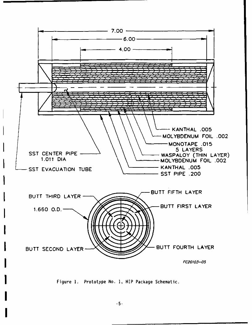
dimensioned and its reinforcement volume fraction verified by calculation.IThe design of the HIP package for fabrication of Prototype No. 1 is shown
schematically in Figure 1. The package was assimbled using standard T304
stainless steel inner and outer pipe sizes. Layers of Fe-Cr-Al (oxidized
Kanthal A) and Mo foil were used to prevent bonding of the composite
layers to the stainless steel envelope. A subassembly consisting of the
outer Fe-Cr-Al, Mo and Waspaloy foil and outer monotape layers was
inserted into the I.D. of the outer pipe first, followed by successive
monotape layers filling toward the center. The five layers of monotape
were sized to form cylinders with butt joints; i.e, no overlapping was
employed. Inner Mo and Fe-Cr-Al foil layers were then added, and the O.D.
of the inner pipe was swaged to fit the remaining opening and inserted
last. The ends of this inner pipe were flared to meet the outer pipe and
seal welded together, along with an evacuation tube at one end. As was
shown in Figure 1, the outer Fe-Cr-Al and Mo layers were shortened to
allow one inch of composite/stainless steel contact at each end. This was
I done to investigate whether diffusion bonding of the composite to the
outer pipe would permit the machining of strong, integrally bonded tensile
I grips into the ends of the outer pipe after consolidation.
I -4-
7.006.00
4.00
L .____.._. KANTHAL .005
------ MOLYBDEN U M- - - FOIL .002
MONOTAPE .0155LAYERS
SST CENTER PIPE WASPALOY (THIN LAYER)1.011 DIA MOLYBDENUM FOIL .002SU KANTHAL .005
STOLNUDSST PIPE .200
BUTT FIFTH LAYERBUTT THIRD LAYER
1.660 O.D. BUTT FIRST LAYER
I BUTT SECOND LAYER BUTT FOURTH LAYER
FC2010J-05
Figure 1. Prototype No. 1, HIP Package Schematic.
I-5-
I

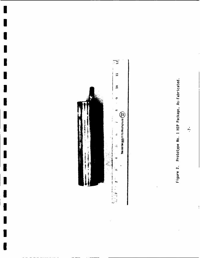
The resultant HIP package was evacuated and internally outgassed at
5500F. It was then successfully leak tested using a mass spectrometer
leak detector, and the evacuation tube sealed off by welding. The
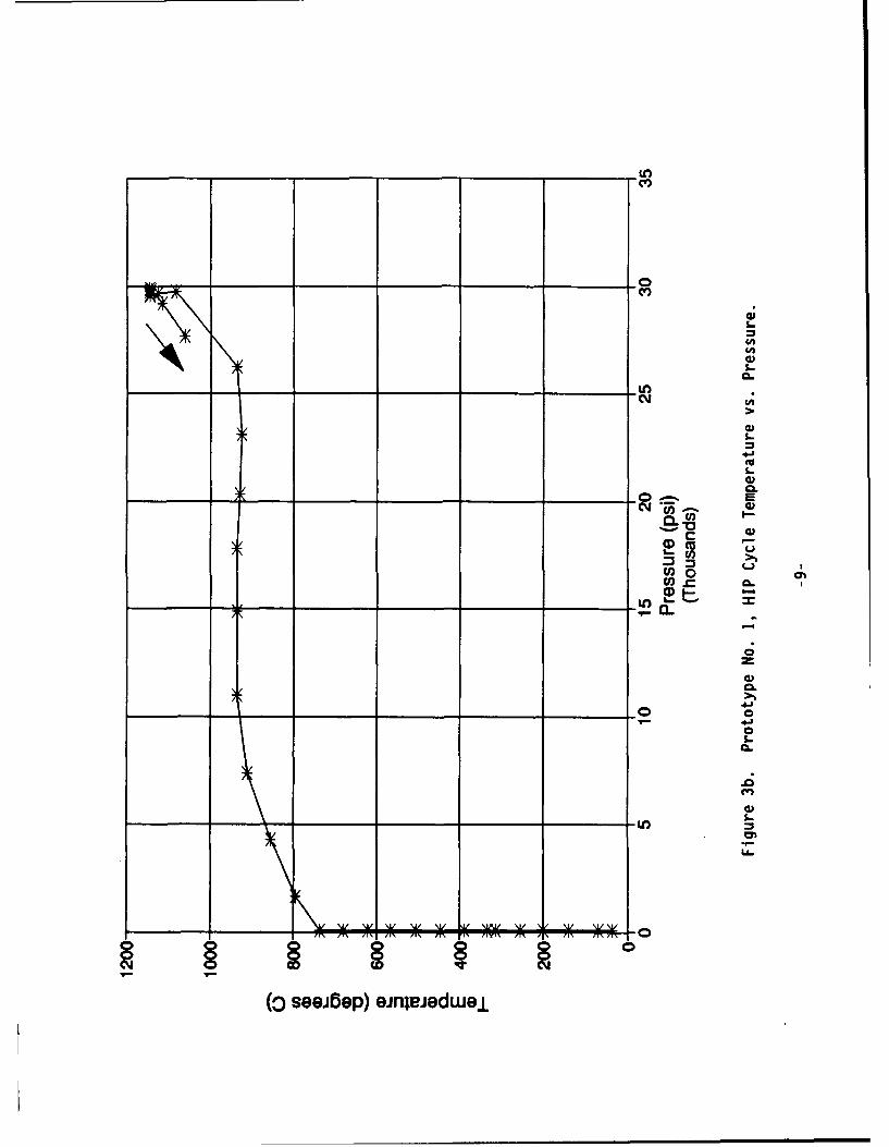
completed package is shown in Figure 2. It was then consolidated in a
2100OF - 30,000 psi - 20 minute HIP cycle. The parametric configuration
of the HIP cycle is shown in Figures 3a and 3b, and the as-HIP'd Package
is shown in Figure 4.
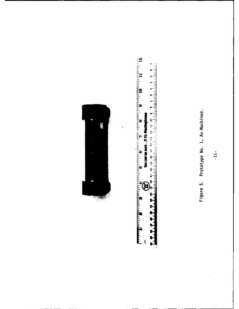
The consolidated HIP package was machined to remove the inner pipe and the
center 4 inches of the outer pipe (down-to the composite surface), as
shown in Figure 5. This left in place the one-inch end sections of the
outer stainless steel pipe which were diffusion bonded to the composite
tube. The I.D. and exposed 4-inch section on the O.D. of the composite
tube were glass bead blasted and etched to remove any traces of adherent
Mo foil. A 1.25-inch long end section was cut off and its ends surface
ground parallel to one another and perpendicular to the tube axis. This
section was then used to evaluate the strength of the composite/stainless
steel diffusion bond. The data from this evaluation is shown in Table 1.
Table 1. Strength of ComDosite/Stainless Steel Diffusion Bond
Bond Region Dimensions: 1.22 inch diameter x 0.908 inch long
Bond Area: 3.48 inA2
Load Stress Deflection(ounds (i) (inches)
0 0 0.0000
5500 1580 0.0140
11000 3161 0.0296
16500 4741 0.0450
22000 6322 0.0604
27500 7902 0.0760
33000 9483 0.0920
(Note: Sample did not fail at 33,000 pounds)
I-6-I
IIIII -
I4=)aEUI US.-
~0EU
- LL.
I ja,EU
a C EU48 01 0='4 =
a -
0
i~Z a,C.I ~1 0
0U I-A 0=
I ii, Sa,L
ItI Uii
IIIII

(seejbep) ejnjedwue
____ 00
FLl
IA
m- cm I-a,
(spuesnoL
(Isd) jnsss,
-cv,
S.-
a,
CLL
S-
A A A OK P
seei~e) einjiGdweu

Eu
WEu
.L aL
- 0
IIEl
V*0
ZIP
The opposite face of the composite tube at the sectioning cut was
metallographically prepared and polished. Photographs of the
microstructure are shown in Figure 6. The cross section shows several
areas in which serious anomalies exist in the composite structure. Areas
are seen where fewer than the as-assembled five uniform rows of tungsten
fibers are present, and severe localized tube wall thinning is present at
two of these locations. These results were attributed to some combination
of local yielding plus butt joint opening due to the HIP cycle pressure
applied to the tube I.D., with adjacent layers filling in the voids in the
latter case.
Dimensional measurements on the composite tube revealed it to be out-of-
round. The O.D. ranged from 1.210 to 1.240 inches, while the I.D. range
was 1.118 to 1.149 inches. (A check with the HIP vendor revealed that the
tube had been loaded horizontally in the HIP unit, and its cross section
may have sagged at temperature). The composite tube wall thickness was
nominally 0.046 inches, representing an approximate 39 percent reduction
of the original 0.075 inch thickness of the five monotape layers prior to
consolidation.
Based on the above, the deficiencies in Prototype No. 1 are summarized
below:
o Cross section out-of-round.
o Localized anomalies in reinforcement layers.
o Localized tube wall thinning.
In view of these deficiencies, it was decided in telecons between W. P.
Blankenship of Westinghouse and Dr. Bahei-El-Din that a second prototype
should be designed and fabricated in order to verify the proposed
approaches to their elimination. This is described in the following
section.
-12-

4-3
S-
0'01-0 0
Q.)
1-
is~
O-AQ 0

IIDesign and Fabrication of Prototype No. 2
A second but smaller prototype was designed incorporating ideas for a
simpler and more viable configuration. By careful layout, short 3-inch
long sections were cut from the monotapes already produced for the
fabrication of the 15-inch long deliverable tubes. In this manner a 4-ply
prototype could be fabricated without incurring additional material or arc
spraying costs. The configuration of the Prototype No. 2 HIP package is
shown in Figure 7.
This new configuration utilized the same size outer stainless steel pipe
used for Prototype No.1 but eliminates the inner and outer layers of
Fe-Cr-Al foil and the inner layer of Mo foil. To permit modifying the
consolidation process, the inner package member was changed to a solid
stainless steel rod which was coated with a 0.0005-inch layer of Mo by
electron beam vapor deposition. This would constrain the HIP cycle
pressure to be applied only to the outer surface and ends of the package,
thus ensuring inward consolidation. The rod and the outer 0.002-inch Mo
foil were painted with a Y203 slurry to help prevent diffusion
bonding. The ends of the outer pipe were counterbored to receive simple
stainless steel discs as end closures. An evacuation tube was welded into
the center of one end disc. The boron nitride rings were added to
facilitate decladding of the composite tube after consolidation.
I Assembly of the package was similar to that of Prototype No. 1, with the
outer layers inserted into the envelope first and successive layers
filling toward the center. The innermost monotape and center rod were
inserted together to prevent scraping the Y203 coating off the rod.
Inserting the boron nitride rings and stainless steel discs completed the
assembly.
After welding the end closures, the package was evacuated and outgassed at
5500F, successfully leak tested and sealed off. It was then loaded
vertically in the vendor's HIP unit and consolidated in a 2100OF -
29,000 psi - 20 minute HIP cycle. The detailed parametric configuration
data for this cycle is not available.
-14-
Im
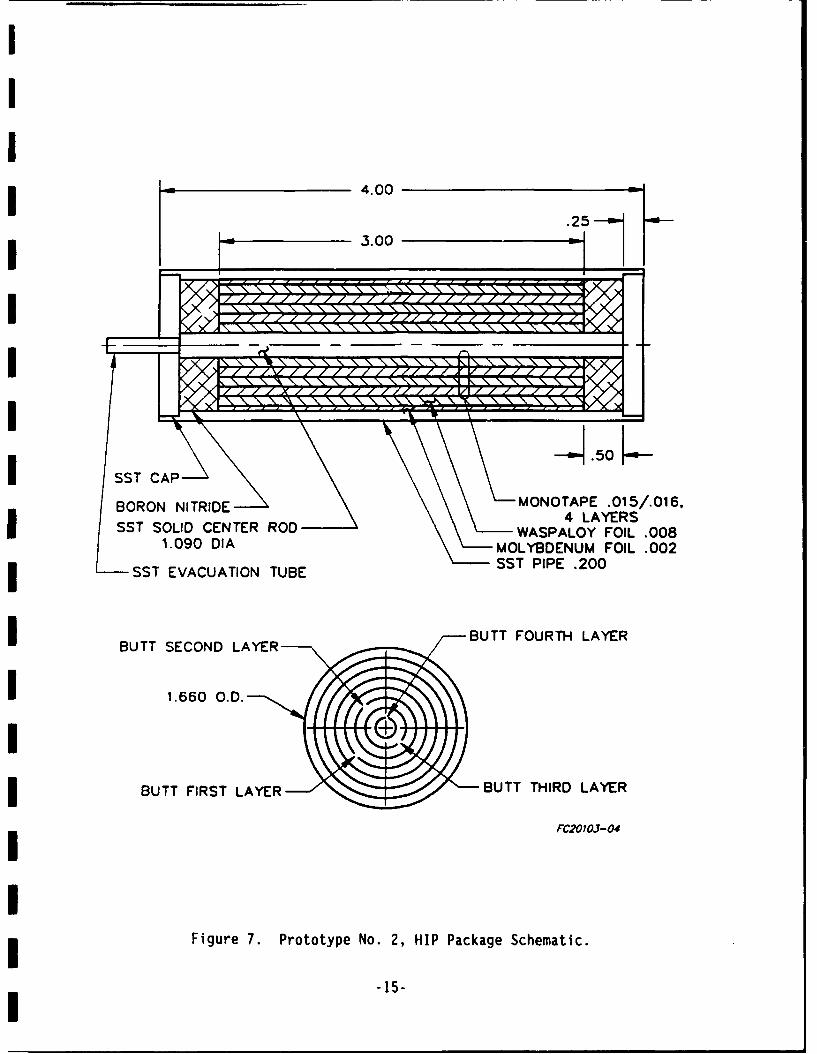
I
I4.00 2
, _ 3.00
I / .O\ ~ ~ ~ ~ :: 7:4\\\ \\\ \ '\\
~....
BORON NITRIDE MONOTAPE .015/.016,SST SLID ENTE ROD4 LAYERS
SST SLID ENTE RODWASPALOY FOIL .0081.090 DIA MOLYBDENUM FOIL .002
ISST EVACUATION TUBE SST PIPE .200
BUTT SECOND LAYER BUTT FOURTH LAYER
1.660 O.D.
BUTT FIRST LAYER BUTT THIRD LAYER
FC20103-04
Figure 7. Prototype No. 2, HIP Package Schematic.
-15-
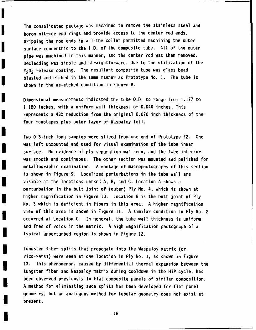
The consolidated package was machined to remove the stainless steel and
boron nitride end rings and provide access to the center rod ends.
Gripping the rod ends in a lathe collet permitted machining the outer
surface concentric to the I.D. of the composite tube. All of the outer
pipe was machined in this manner, and the center rod was then removed.
Decladding was simple and straightforward, due to the utilization of the
Y203 release coating. The resultant composite tube was glass bead
blasted and etched in the same manner as Prototype No. 1. The tube is
shown in the as-etched condition in Figure 8.
Dimensional measurements indicated the tube O.D. to range from 1.177 to
1.180 inches, with a uniform wall thickness of 0.040 inches. This
represents a 43% reduction from the original 0.070 inch thickness of the
four monotapes plus outer layer of Waspaloy foil.
Two 0.3-inch long samples were sliced from one end of Prototype #2. One
was left unmounted and used for visual examination of the tube inner
surface. No evidence of ply separation was seen, and the tue interior
was smooth and continuous. The other section was mounted aiid polished for
metallographic examination. A montage of macrophotographs of this section
is shown in Figure 9. Localized perturbations in the tube wall are
visible at the locations raarkce A, B, and C. Location A shows a
perturbation in the butt joint of (outer) Ply No. 4, which is shown at
higher magnification in Figure 10. Location B is the butt joint of Ply
No. 3 which is deficient in fibers in this area. A higher magnification
view of this area is shown in Figure 11. A similar condition in Ply No. 2
occurred at Location C. In general, the tube wall thickness is uniform
and free of voids in the matrix. A high magnification photograph of a
typical unperturbed region is shown in Figure 12.
Tungsten fiber splits that propogate into the Waspaloy matrix (or
vice-versa) were seen at one location in Ply No. 1, as shown in Figure
13. This phenomenon, caused by differential thermal expansion between the
tungsten fiber and Waspaloy matrix during cooldown in the HIP cycle, has
been observed previously in flat composite panels of similar composition.
A method for eliminating such splits has been developed for flat panel
geometry, but an analogous method for tubular geometry does not exist at
present.
-16-
IA
IjcIcIioc
L-

IIIIIII
IIII1
I D,",~ ~ crq~ c Snct icr
C.
I
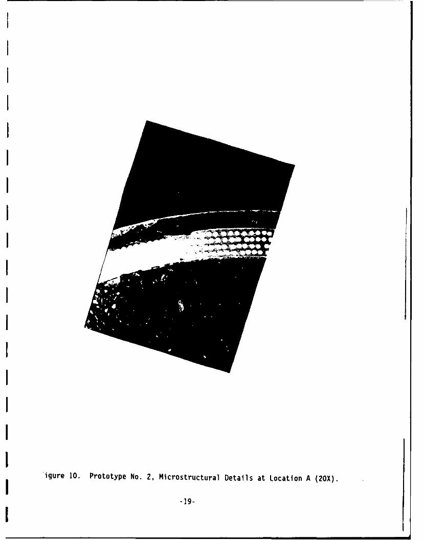
III
IIII
igure 10. Prototype No. 2, Microstructural Details at Location A (20X).19-
I

I.IIIIIIIII1IIIIII
Figure 11. Prototype No. 2, Microstructural Details at Location B (80X).
-20-
I

0000Q@
I .
11 O000004
Figure 12. Prototype No. 2, Microstructural Details ofTypical Unperturbed Region (80X).
-21-

Figure 13. Prototype No. 2, Tungsten Fiber Splits in Ply No. 1 (200X).
-22-
The tungsten/Waspaloy interdiffusion reaction zone developed during HIP is
seen for a typical fiber in Figure 14. The zone thickness, nominally
0.0001 inches, is within the range of acceptability for achieving good
fiber/matrix bonding without developing brittle intermetallic
characteristics.
From the above evaluation, it was concluded that a major improvement in
composite tube structural uniformity and freedom from serious
perturbations had been achieved with the Prototype No. 2 assembly and
processing approach. However, it is doubtful that complete freedom from
localized perturbations can ever be achieved with an assembly of
individual butt-jointed plies. A multiple-ply spiral wrap assembly made
from a single continuous width monotape might yield superior results, but
fabricating a superalloy matrix monotape of such width is beyond the
capability of our state-of-the-art methodology.
A meeting was held at RPI on December 12, 1990 to review the status of the
project. A presentation was made detailing the results of the first two
prototype tubes and noting the inescapable trial-and-error nature of this
first-of-a-kind project. Agreement was reached on the approach to be
taken in fabricating full length deliverable tubes, and that the scope
would be modified to require delivery of only one 15-inch product. The
key change to be implemented was to overlap the outer monotape a small
amount (5 or 6 fibers) to eliminate the perturbation on the O.0. of the
composite tube. At the same time, it was agreed that the scope of work
would be expanded to include fabrication of a flat panel of Waspaloy foil
to permit RPI to fabricate and test samples of unreinforced matrix
material.
-23-

i
I ,I
I, .... a" ,I
III
I Figure 14. Prototype No. 2, Typical Tungsten Fiber/Waspaloy
Matrix Interdiffusion Reaction Zone (500X).
i -24-
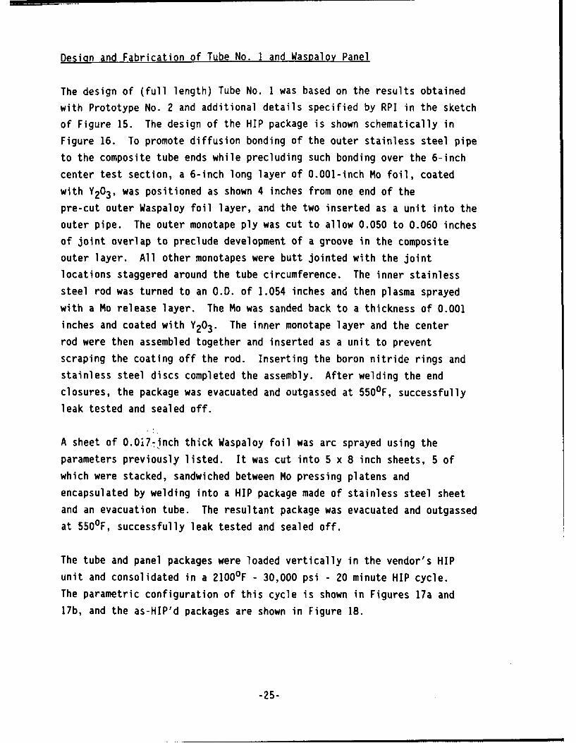
Design and Fabrication of Tube No. I and Waspaloy Panel
The design of (full length) Tube No. I was based on the results obtained
with Prototype No. 2 and additional details specified by RPI in the sketch
of Figure 15. The design of the HIP package is shown schematically in
Figure 16. To promote diffusion bonding of the outer stainless steel pipe
to the composite tube ends while precluding such bonding over the 6-inch
center test section, a 6-inch long layer of 0.001-inch Mo foil, coated
with Y203 , was positioned as shown 4 inches from one end of the
pre-cut outer Waspaloy foil layer, and the two inserted as a unit into the
outer pipe. The outer monotape ply was cut to allow 0.050 to 0.060 inches
of joint overlap to preclude development of a groove in the composite
outer layer. All other monotapes were butt jointed with the joint
locations staggered around the tube circumference. The inner stainless
steel rod was turned to an O.D. of 1.054 inches and then plasma sprayed
with a Mo release layer. The Mo was sanded back to a thickness of 0.001
inches and coated with Y203. The inner monotape layer and the center
rod were then assembled together and inserted as a unit to prevent
scraping the coating off the rod. Inserting the boron nitride rings and
stainless steel discs completed the assembly. After welding the end
closures, the package was evacuated and outgassed at 5500F, successfully
leak tested and sealed off.
A sheet of 0.0i77inch thick Waspaloy foil was arc sprayed using the
parameters previously listed. It was cut into 5 x 8 inch sheets, 5 of
which were stacked, sandwiched between Mo pressing platens and
encapsulated by welding into a HIP package made of stainless steel sheet
and an evacuation tube. The resultant package was evacuated and outgassed
at 5500F, successfully leak tested and sealed off.
The tube and panel packages were loaded vertically in the vendor's HIP
unit and consolidated in a 2100°F - 30,000 psi - 20 minute HIP cycle.
The parametric configuration of this cycle is shown in Figures 17a and
17b, and the as-HIP'd packages are shown in Figure 18.
-25-
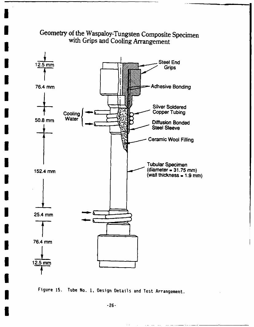
Il
i Geometry of the Waspaloy-Tungsten Composite Specimenwith Grips and Cooling Arrangement
Steel End12.5 mm Grips
76.4 mm Adhesive BondingISilver Soldered
ooln Copper Tubing50.8 mm Water Diffusion Bonded
Steel Sleeve
_- Ceramic Wool Filling
3 Tubular Specimen152.4 mm (diameter- 31.75 mm)
(wall thickness - 1.9 mm)II 25.4 mm
76.4 mm
12.5 mm
Figure 15. Tube No. 1, Design Details and Test Arrangement.
-26-
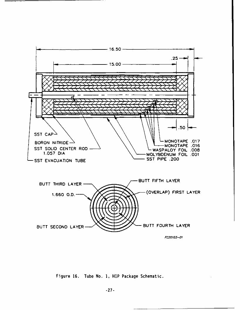
16.50 ON
.2515.00
.- ~~~~ - - -- - - - -- -. . . . . .. .
/, N 'IN 'IN 'IN %I N 1 1 '\ 1 1.. . . -. . . . . . . . . . ......,
BORON NITRIDE NMONOTAPE .017
-- MONOTAPE ,016SST SOLID CENTER ROD WASPALOY FOIL .008
1.057 DIA MOLYBDENUM FOIL .001SST EVACUATION TUBE SST PIPE .200
BUTTTHIR LAYR--- /-BUTT FIFTH LAYER
BUTT SECOND LAYER - -- BUTT FOURTH LAYER
PC20703-0!
Figure 16. Tube No. N, HIP Package Schematic.
-27-

(o seeJbep) einiejedwe±
0v 0 0 0co co v 00
~j~- L ~ ~L-
Ic
C'hJ
CLjEE
000 (-
0)
-n Lc L
CV T"I 0esoL
(!sd) jnssG)

IfI ___ __ _ ________ _ __ ___ __04
____ _ __ _______ _ __ ___ ____ _ .
V))
Lo.
LoL
I LA-
CM Go co I
(o sei~e) sijejewa)

IIIIII
0
C0I
C
I di
0
(00a-I a-
0)C
* 0'0
0I 0a.0
0I 0C
I 0z0)
-c
Ia,I 0)
I-.
C.)
LL.
IIII

mThe panel package envelope was machined away in a straigtforward manner to
I yield the flat panel of unreinforced Waspaloy. The surfaces were glass
bead blasted and etched to remove any traces of the Mo foil release
layers. The completed panel is shown in Figure 19. Its thickness was
0.056 inches thick, representing a 34 percent reduction from the
m as-sprayed foil thickness.
The tube package was machined to the configuration specified in the RPI
sketch of Figure 20, and the center rod removed to yield the composite
tube with diffusion bonded stainless steel grip sections at each end. The
m stainless steel end sections were masked with a stop-off lacquer, and the
outer surface of the center section was glass bead blasted and etched.
The completed tube is shown in Figure 21. The as-HIP'd tube I.D. was
quite uniform, with all measurements in the range 1.056 to 1.057 inches.The as-machined O.D. of the stainless steel grip sections was 1.350
inches, and that of the composite center section approximately 1.175
inches. The outer layer of Waspaloy matrix material was irregular in
texture and contained several shallow, extended grooves. It appeared thatthe outer Mo foil release layer had wrinkled during the HIP consolidation,
and that the texture of the wrinkles was reproduced in the Waspaloy
surface layer. A thin slice was cut from the longer grip end of the tubeand prepared for metallographic examination. The microstructure is shown
in Figure 22. The fiber distribution and ply-to-ply relationship are
reasonably uniform. The 0.060-inch wide localized void seen in the matrix
between fiber layers 2 and 3 is an anomaly related to the fact that the
section was taken at the very end of the monotape layers. These ends are
somewhat ragged and the occurance of a void or inclusion of some sort isnot surprising. In subsequent processing, this void disappeared after
removing less than 0.050 inches of the tube end.
After discussing the unexpected Waspaloy surface condition in a telecon
with Dr. Bahei-El-Din, this first-of-a-kind composite tube (together with
the completed panel) was shipped to RPI for their examination. In a
subsequent telecon discussion between W. P. Blankenship and Dr. G. J.Dvorak of RPI, Dr. Dvorak expressed concern that some of the outer surfacelayer irregularities might act as crack initiation sites during mechanical
testing. It was agreed that the tube would be returned to AES for
3 evaluation of approaches to removing the subject irregularities.
-31-I
IIIIIII
a)CI Eu
C-
- 0'UI meC-En'U
Va)I 1)L
'40 en
CI a)I..C
I 0~a)LI
LL
IS
IIIUI
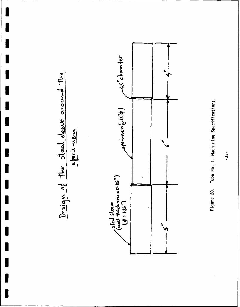
IIII
4
I .4
II 0
;e~. 'U
U
4-
U
I C* 1*.3,I :1'U
z
I iA~ 0
.0I ih~gp I-
II 0
6*AI I-
.Ai UUV) - -D.i'I Lh..I
-mlT~3I
IIII

UIII -
III
V0)-c(-)
LaJICi~K I
E~s~- 3 -
3 0).0
I I-.
eJ
U -*4 I-U- Li...
IIIIIU
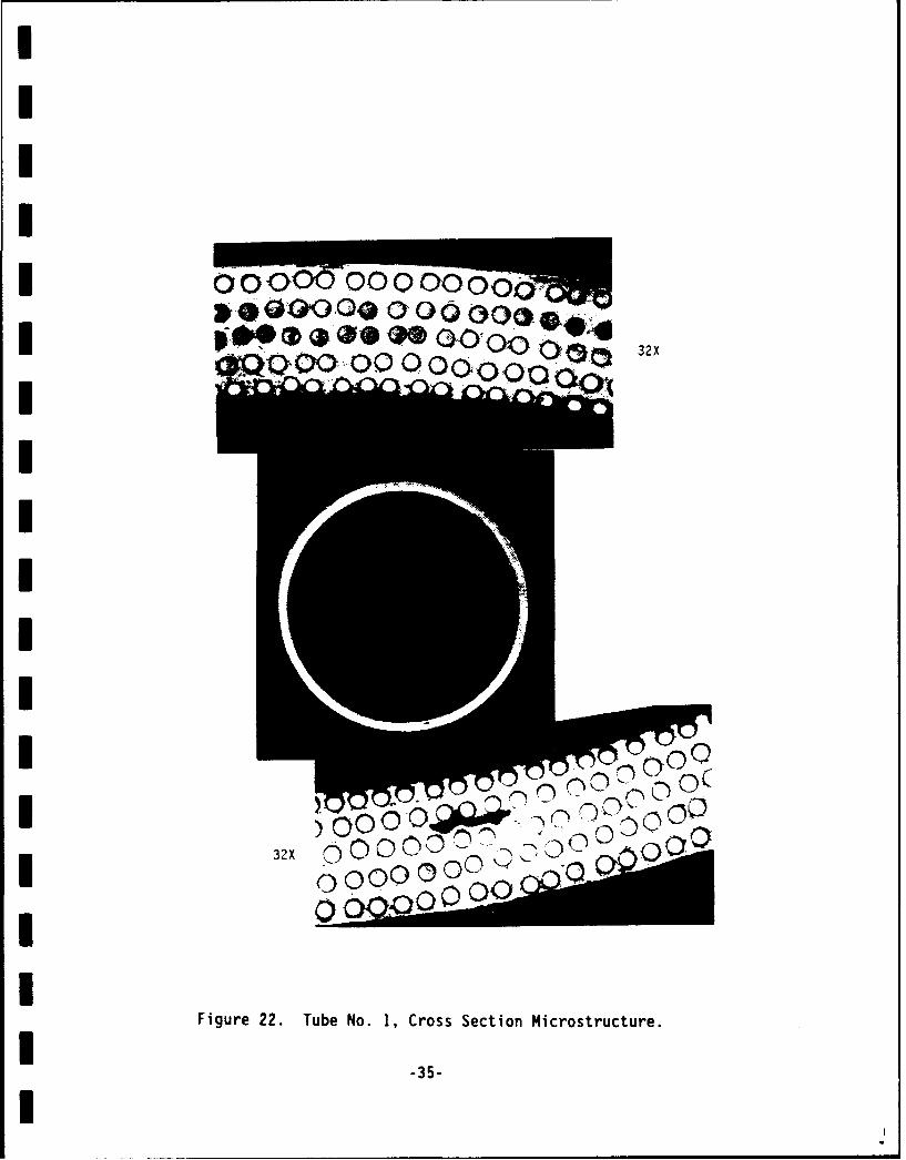
III
.00032
0 0000
Iif:
I0
Ir -u N, o s eOt000i u cIII
I 2x 0 OO0 - D4 0 O i
IFigure 22. Tube No. 1, Cross Section Microstructure.
1 -35-
I
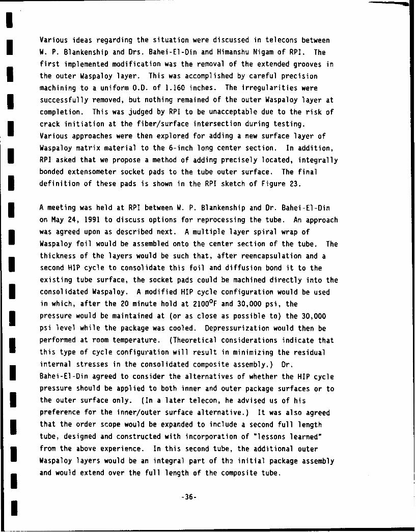
Various ideas regarding the situation were discussed in telecons between
I W. P. Blankenship and Drs. Bahei-El-Din and Himanshu Nigam of RPI. The
first implemented modification was the removal of the extended grooves in
the outer Waspaloy layer. This was accomplished by careful precision
machining to a uniform O.D. of 1.160 inches. The irregularities were
successfully removed, but nothing remained of the outer Waspaloy layer at
completion. This was judged by RPI to be unacceptable due to the risk of
I] crack initiation at the fiber/surface intersection during testing.
Various approaches were then explored for adding a new surface layer of
Waspaloy matrix material to the 6-inch long center section. In addition,
RPI asked that we propose a method of adding precisely located, integrallybonded extensometer socket pads to the tube outer surface. The final
I definition of these pads is shown in the RPI sketch of Figure 23.
I A meeting was held at RPI between W. P. Blankenship and Dr. Bahei-El-Din
on May 24, 1991 to discuss options for reprocessing the tube. An approach
I was agreed upon as described next. A multiple layer spiral wrap of
Waspaloy foil would be assembled onto the center section of the tube. The
thickness of the layers would be such that, after reencapsulation and a
second HIP cycle to consolidate this foil and diffusion bond it to theexisting tube surface, the socket pads could be machined directly into the
S consolidated Waspaloy. A modified HIP cycle configuration would be used
in which, after the 20 minute hold at 2100OF and 30,000 psi, the
I pressure would be maintained at (or as close as possible to) the 30,000
psi level while the package was cooled. Depressurization would then be
I performed at room temperature. (Theoretical considerations indicate that
this type of cycle configuration will result in minimizing the residual
internal stresses in the consolidated composite assembly.) Dr.
Bahei-El-Din agreed to consider the alternatives of whether the HIP cycle
pressure should be applied to both inner and outer package surfaces or to
S the outer surface only. (In a later telecon, he advised us of his
preference for the inner/outer surface alternative.) It was also agreed
m that the order scope would be expanded to include a second full length
tube, designed and constructed with incorporation of "lessons learned"
m from the above experience. In this second tube, the additional outer
Waspaloy layers would be an integral part of th3 initial package assembly
H and would extend over the full length of the composite tube.
-36-l
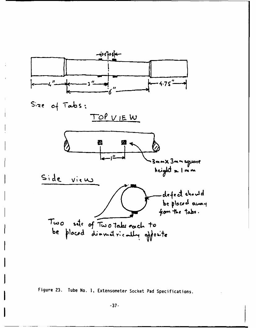
3
7- V. IF,
II
l-2.-*x 3f-4 s ae
Figure 23. Tube No. 1, Extensometer Socket Pad Specifications.
-37-
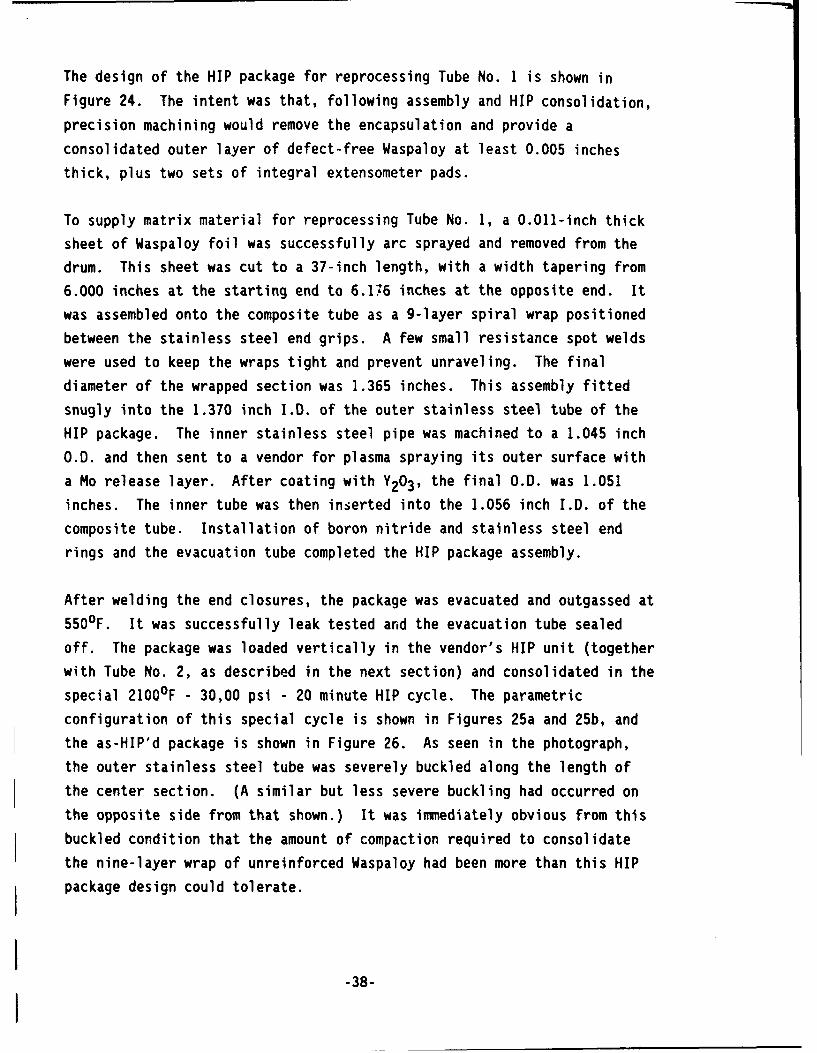
The design of the HIP package for reprocessing Tube No. 1 is shown in
Figure 24. The intent was that, following assembly and HIP consolidation,
precision machining would remove the encapsulation and provide a
consolidated outer layer of defect-free Waspaloy at least 0.005 inches
thick, plus two sets of integral extensometer pads.
To supply matrix material for reprocessing Tube No. 1, a 0.011-inch thick
sheet of Waspaloy foil was successfully arc sprayed and removed from the
drum. This sheet was cut to a 37-inch length, with a width tapering from
6.000 inches at the starting end to 6.176 inches at the opposite end. It
was assembled onto the composite tube as a 9-layer spiral wrap positioned
between the stainless steel end grips. A few small resistance spot welds
were used to keep the wraps tight and prevent unraveling. The final
diameter of the wrapped section was 1.365 inches. This assembly fitted
snugly into the 1.370 inch I.D. of the outer stainless steel tube of the
HIP package. The inner stainless steel pipe was machined to a 1.045 inch
O.D. and then sent to a vendor for plasma spraying its outer surface with
a Mo release layer. After coating with Y203 , the final O.D. was 1.051
inches. The inner tube was then inserted into the 1.056 inch I.D. of the
composite tube. Installation of boron nitride and stainless steel end
rings and the evacuation tube completed the HIP package assembly.
After welding the end closures, the package was evacuated and outgassed at
5500F. It was successfully leak tested and the evacuation tube sealed
off. The package was loaded vertically in the vendor's HIP unit (together
with Tube No. 2, as described in the next section) and consolidated in the
special 2100OF - 30,00 psi - 20 minute HIP cycle. The parametric
configuration of this special cycle is shown in Figures 25a and 25b, and
the as-HIP'd package is shown in Figure 26. As seen in the photograph,
the outer stainless steel tube was severely buckled along the length of
the center section. (A similar but less severe buckling had occurred on
the opposite side from that shown.) It was immediately obvious from this
buckled condition that the amount of compaction required to consolidate
the nine-layer wrap of unreinforced Waspaloy had been more than this HIP
package design could tolerate.
-38-
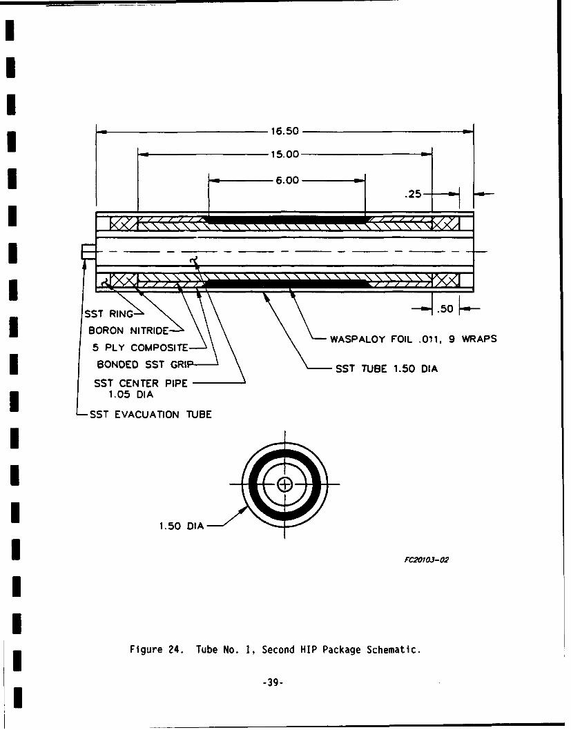
16.50
15.00
6.00
SST RIN .50
NII
* BORON NITRIDEWASPALOY FOIL .011. 9 WRAPS
5 PLY COMPOSITE
BONDED SST GRI SST TUBE 1.50 DIA
SST CENTER PIPE1.05 DIA
SST EVACUATION TUBE
U 1.50 DIA
I FC2OLO3a-02
!I
Figure 24. Tube No. 1, Second HIP Package Schematic.
-39-I
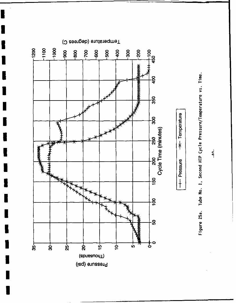
3 (o seejbep) einjeedwejL
CY0 0 0 0 00c0J-O 0o r o U w c l
co a
cy E
(DU
EE
IK, 4: 14 00)
00
*n Ln 0m _1 _ 0
(spesa)j(!sd) jnssGU
Ut iIc
Lo)
00
VI-
(o sekep eijejewow
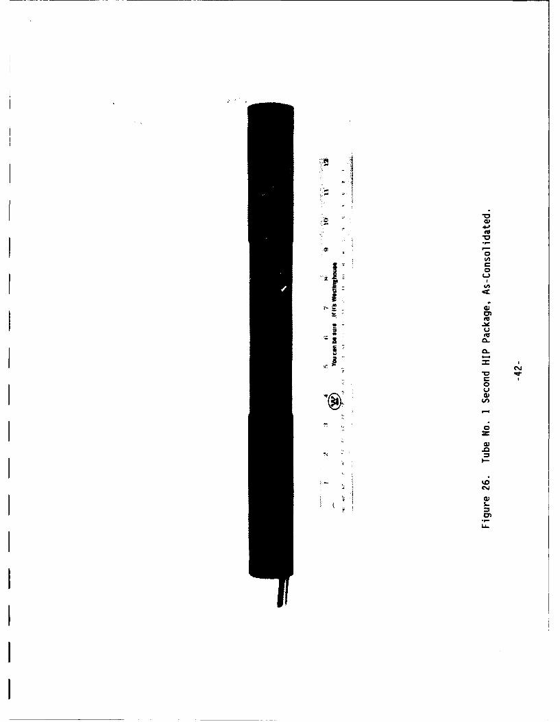
I-1-ca,0
*0
a I-0
* C0
I-(4I- C
C a,- C.'
0* S* U* 0a-
-4I C-It)
VC0U
(0
-4
0za,
.0-4
toC..,
a,1-
t
0.'LL

Machining was initiated to bring the tube to the configuration shown
previously in Figure 23. The O.D. was turned to 1.350 inches to
reestablish the stainless steel grip dimension. Then the locations of the
extensometer socket pads and the grip section inboard end chamfers were
layed out, and machining of these features initiated. Machining proceeded
in 0.005-inch diametral increments, with a target diameter of 1.170
inches: based on the as-assembled diameter of 1.160 inches, this would
provide a 0.005-inch thick outer layer of Waspaloy covering the outermost
layer of fibers. However, when machining the region between the short
grip end and the adjacent pad precursor ring, reinforcing fiber was
exposed at a diameter of 1.182 inches. Similarly, in the region between
the two pad precursor rings, fiber was exposed at a diameter of 1.206
inches. Machining was terminated at this point. The overall package
appearance at this stage is shown in Figure 27, and a closeup of one
exposed fiber region is shown in Figure 28. The application of HIP
pressure to the package I.D. had obviously expanded the composite outward
along the center section between the original grips, with the amount of
expansion increasing toward the midpoint of this section. This is
illustrated more quantitatively in Figure 29. It was concluded with
hindsight that a better approach to reprocessing Tube No. I would have
been to apply HIP pressure to the outer surfaces only.
It was decided that the tube would be reworked by plasma spraying a layer
of nickel base superalloy onto the regions between the pad precursor rings
and the grips, and then machining the plasma-sprayed layer to a
conservative final diameter. Dr. Nigam was advised of this decision in a
telecon with W. P. Blankenship. Waspaloy is not commercially available as
a plasma spray powder, so METCO 461, a standard plasma spray alloy of
composition Ni-17.5Cr-5.5Al-2.5Co-0.5Y 203, was selected. This alloy
is a good thermal expansion match with Waspaloy (coefficient of thermal
expansion of 13 x 10- 6 °C'l, cf. 12.2 x 10⁻⁶ for Waspaloy), and
has good oxidation resistance to 18000F. The grips, pad precursor rings
and tube center section were masked off, and spraying performed by a local
vendor. The plasma sprayed regions were then machined to a diameter of
1.220 inches, and the pads milled to their final 3mm x 3mm x Imm high
dimensions. The center stainless steel tube was then removed, completing
the fabrication process. The final appearance of Tube No. I is shown in
Figure 30, and a closeup of the center section is shown in Figure 31.
-43-
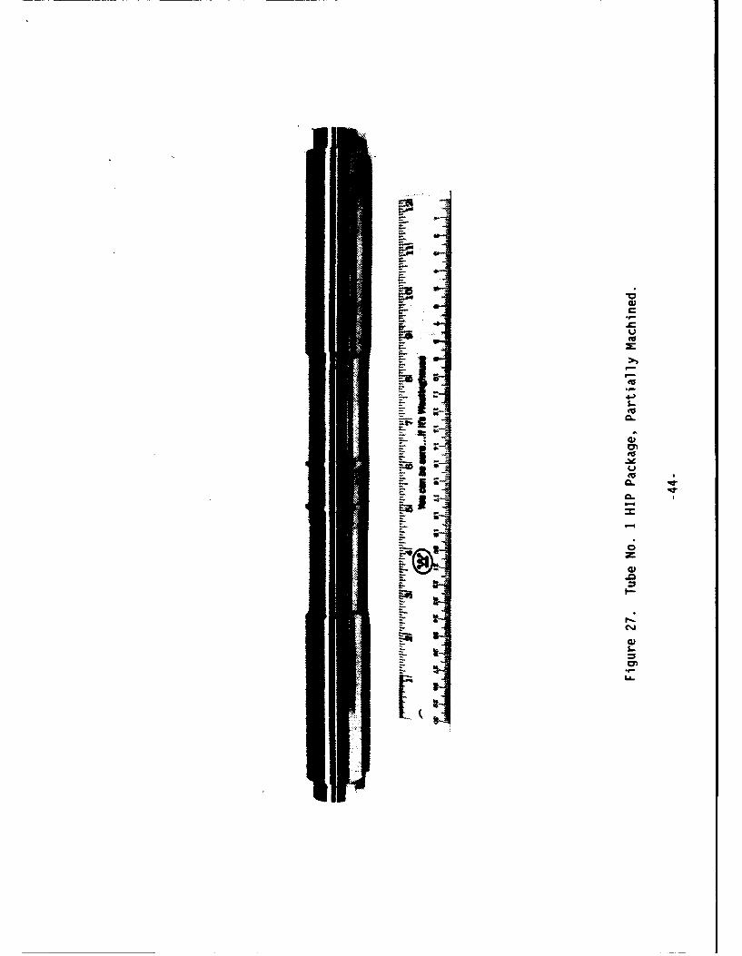
C4
5.
S.-
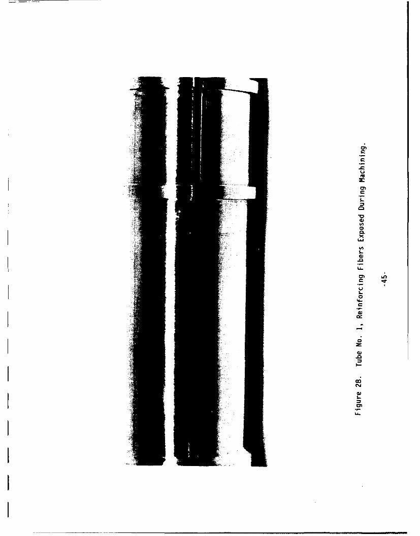
C
CL
L
* a)

41
-CL=
C)C
4-
CLC
0f) mU
U5-
(D a
ca,
VEU
CL -
.m 0 m 0
ou CI)~ -e~ ien o- O
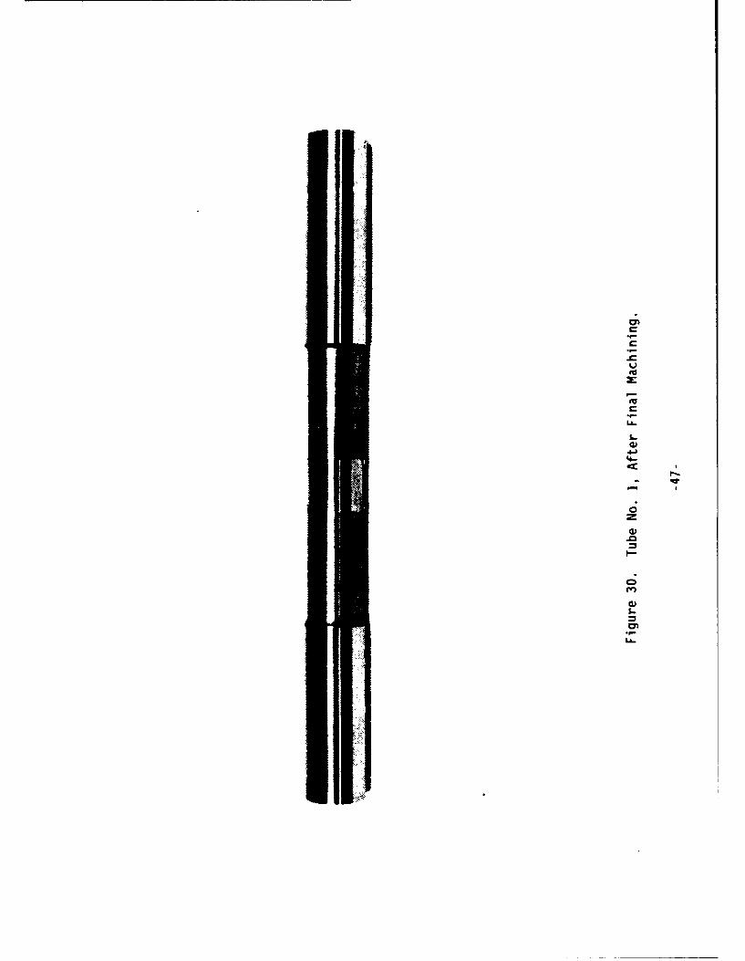
C
C
-cU(US
(UC
S.-C)
4-C
-
0zC)
.0
0
C)S..=
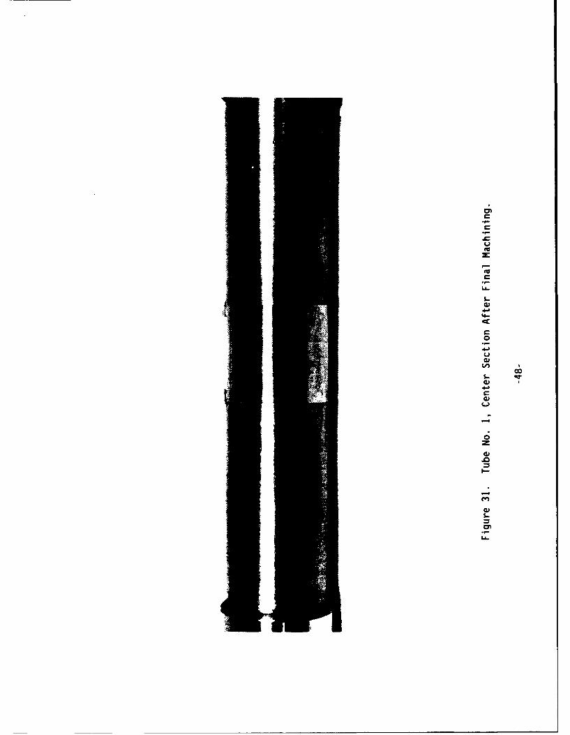
C
C
CLim
S
0
C
LL
1-a,
'4-C
C0
4.)U0)U)
La)
4.)C
L)
0ra,
.0
I.-
Cr)
a)L.

The completed tube was shipped to RPI on July 30, 1991. A meeting was
held at RPI on August 6, 1991 between W. P. Blankenship and Drs.
Bahei-El-Din and Nigam, in which the reprocessing of Tube No. 1 was
discussed in some detail. It was agreed that machining of Tube No. 2,
discussed in the next section, would not be initiated until Dr. Dvorak had
been briefed on the status of the work.
Design and Fabrication of Tube No. 2
The design of the HIP package for Tube No. 2 is shown in Figure 32. In
addition to the 5 monotape layers, 9 outer layers of 0.011-inch Waspaloy
foil were incorporated to provide material for the extensometer socket
pads. Since O.D. machining of the entire tube length would inevitably be
required, no release layer was used between the Waspaloy foil and the
outer stainless steel pipe. As before, the package was assembled from the
outer layer inward. The stainless steel center rod O.D. was machined to
fit the assembly, plasma sprayed with Mo, turned to a final O.D. of 1.042
inches and coated with Y203. It was mated with the innermost monotape
layer and the two inserted as a subassembly to avoid scraping off the
Y203 coating. Installation of the boron nitride rings, stainless
steel end discs and the evacuation tube completed the assembly. After
welding the end closures, the package was evacuated and outgassed at
5500F. It was then successfully leak tested and sealed off.
The package was loaded (together with that for Tube No. 1, described in
the previous section) vertically in a vendor's autoclave and processed in
a specially configured 2100OF - 30,000 psi - 20 minute HIP cycle. The
parametric configuration of this cycle was shown previously in Figures 25a
and 25b. The as-HIP'd package is shown in Figure 33. As seen in this
figure, the outer pipe was severely buckled along the entire length of the
package.
-49-
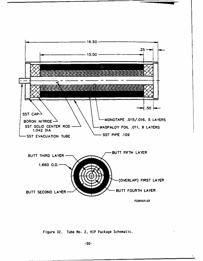
16.50
15.00 - 1
BORON NITRIDE ' MONOTAPE .015//.016, 5 LAYERS
SST SOLID CENTER ROD WASPALOY FOIL .011, 9 LAYERS1.042 DIA
-SST EVACUATION TUBESTPIE.0
BUTT FIFTH LAYERBUTT THIRD LAYER
(OVERLAP) FIRST LAYER
BUTT SECOND LAYER J BUTT FOURTH LAYER
FC2OI03-OJ
Figure 32. Tube No0. 2, HIP Package Schematic.
-50-
LXI/l
vM N/~ml -l -I ll -~I I~l -m - -I -Il l - -I -
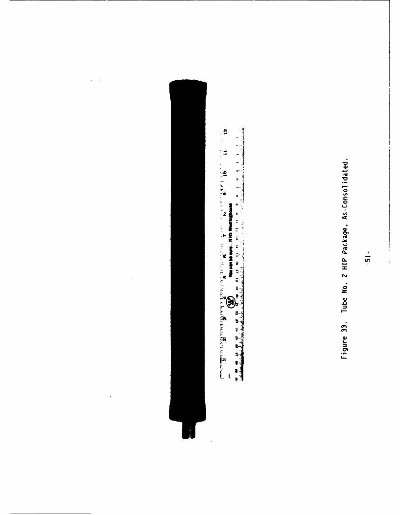
I-oa,0*0
'41 0
tflC0L)U,C
a,0~0
a -~
~00
*2 -
-=
-km c~J
0
r.0
U I-
C,,
"ii a a,I..
LL
K:

In a telecon between W. P. Blankenship and Dr. Nigam, approval was given to
machine Tube No. 2 to essentially the same configuration as Tube No. 1.
Machining of the package was initiated by turning to the 1.350-inch grip
diameter over its entire length. Machining inboard of the grips then proceeded
with the removal of 0.005-inch layers, with a target final diameter of 1.170
inches. However, localized exposure of the outer layer of fibers occurred at a
diameter of 1.182 inches on the short grip end and 1.178 inches on the long
grip end of the center section. Machining of the tube O.D. was terminated at
this point. After completion of milling of the extensometer socket pads, the
center rod was removed to complete the. composite tube decladding process. A
thin slice was removed from one end of the tube, mounted and polished for
metallographic examination. The microstructure is shown in Figure 34. It is
obvious from this photograph that the HIP package buckling produced severe
distortion of the composite structure at Locations A and C. Some 'ess severe
distortion is also seen at Locations B and D. The area at which some outer
fibers were exposed during the final machining pass undoubtedly corresponds to
either Location A or C. As was the case with Tube No. 1, it is obvious from
the buckled condition of the HIP package and resultant distortion of the
composite structure that the amount of compaction required to consolidate the
nine-layer wrap of unreinforced Waspaloy was more than this HIP package design
could tolerate.
The appearance of Tube No. 2 was discussed in a telecon between W. P.
Blankenship and Dr. Nigam, and it was agreed that the tube would be shipped to
RPI for examination. This was done, and resulted in a request from RPI that
the tube be plasma sprayed with a thin layer of METCO 461 to cover the exposed
fibers. The tube was returned to AES and the plasma spraying performed by a
local vendor. After spraying, it was found that a slight bend had developed
near one end of the center section. Most of this effect was removed by
adjusting the setup of the tube in the lathe prior to final machining. The
as-sprayed appearance of the tube center section is shown in Figure 35. Final
machining and polishing was then performed to yield a 0.010-inch METCO 461
layer thickness and a final center section O.D. of 1.190 inches. The completed
tube is shown in Figure 36. Tube No. 2 was shipped to RPI on September 23,
1991, completing the requirements of the original order and subsequent
modifications.
-52-
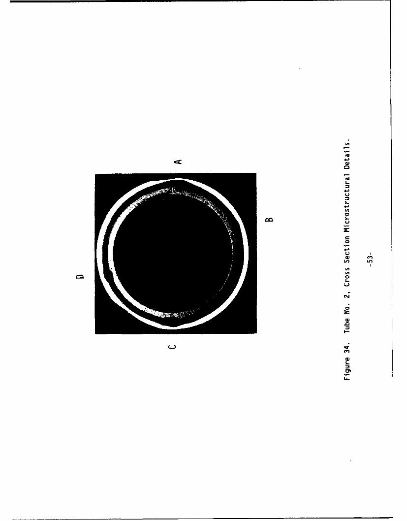
C3
U-
Ln
L.

IIIIII ,~4 4
C
I-I - C
'ho'C.
0I C-,I-LU
4 S
-cI 3-oa)>1toI S..C.It)
U,U,CI ('a
0
rI )-o=I-
InC')
a)S..=I
La~
IIIII

tv
CC
LL.

Conclusions
1. A method was developed for fabricating 4- or 5-ply tungsten-fiber-reinforced Waspaloy-matrix tubes up to 15 inches in length. A fiber
diameter of 0.006 inches and fiber volume fraction of 0.35 were
successfully incorporated. Key features of the method include:
o Using a solid rod as the center member of the HIP package, thus
constraining application of the HIP cycle pressure to the package
outer surfaces only.
o Using sprayed coatings of HIP package release layers rather thanseparate layers of foil.
0 Limiting the thickness of the unreinforced outer layer ofWaspaloy matrix material in the HIP package to 0.010 inches or
less.
2. While a reasonably uniform composite structure was obtained using a
multilayer assembly of butt-jointed plies, some perturbations in the
structure at the butt joint locations are probably inevitable.
3. Serious difficulties were encountered in attempting to add integrally
consolidated and bonded Waspaloy extensometer socket pads to the outersurfaces of the composite tubes. Both of the approaches attemptedresulted in moderate to severe distortion of the composite structure
and/or the tube geometry.
4. Some of the problems resulting from the above distortions were
successfully mitigated by plasma spraying the composite tube with alayer of the oxidation resistant superalloy METCO 461.
5. One 4-ply and one 5-ply sublength prototype and two 15-inch long 5-ply
tubes were fabricated, together with a flat panel of unreinforced
Waspaloy, and delivered to RPI.
-56-
Recommendations
1. Order at least one additional 15-inch tube to be fabricated without
the additional outer layers of Waspaloy foil.
2. Investigate alternative approaches to adding extensometer socket pads
to the tube outer surface. Possibilities include machining the pads
from a diffusion bonded HIP package outer pipe, attaching separately
machined pads by resistance spot welding, and machining the pads from
METCO 461 (or similar) alloy plasma sprayed onto the tube surface
after tube fabrication is complete. These approaches should be
investigated on relatively inexpensive subscale models prior to
committing one of them to a full size composite tube.
3. If possible, make future composite tubes longer than the final
required size to permit sectioning for metallographic examination well
inboard of the ends of the composite plies.
-II
-57-I