· created date: 6/28/2010 8:45:03 pm
TRANSCRIPT

SPEAKER SYSTEM
cs-A700

cs-A7001. SPECIFICATIONS
Enclosure:Speakers:
Woof er
Mid range
Tweeterlnput impedance:Frequency range:
Sensitivity:Maximum inputpower:Crossover frequency:
Totally enclosed t\rpe
12"(30cm) cone type5"(12cm) cone typeMulti-cellular horn type8 ohms35 to 20,000H295dB/W at 1m distance60w
'e
Lows. .. Midranges 500H2Midranges ..... Highs 5,000H2
(ln case multi-channel amplifiers are used)
2-channel amplifiers:Lows . . Mid-ranges and Highs
3-channel amplifiers:Lows. .. MidrangesMidranges ..... Highs
External dimensions:
Weight:NOTE:
500 to 1,000H2
500 to 1.000H24,000 to 6,000H2660(H) x 380(W) x 320(D)mm26"(H) x 15"(W) x 12 19132"(Dl16.9ks (37 lb3 oz)
Specifications and the design subject to possible modification without noticedue to improvements.
1t0
L|STENIT rw ---lt --z
........ \=r rlNClll5/A rNoihAL/'K; t;,,";; ^V.r;{\'
o i00
7soU2ao
|#70
60
6 t00
3so
260
H?o60
30
a ?5
za ro
A r5
!'05
200 500
FREQU FNC Y
n00 2wI N liz
-4\40'
a0\ \.,^"/
240 500 1000 2000
FREQUENCY I N Hz
200 500 lmFREQUENcY i N Hz
sma.

b.
V. REPLACEMENT OF NETWORK UNIT
Remove all of the speakers according toItem 2.Remove all screws from the back board.Now, the board is still held to the back ofthe cabinet by 4-pinch clips inside of thecabinet, two on the upper side and two onthe lower side.Remove the back board by gently rappingon both its upper and lower sides throughthe opened speaker hole in the baffle.After removal of the back board,disconnectall lines.The network is secured firmly by meansof a binding agent as well as tackers. Ifonly a coil or a capacitor has been damaged,it is advisable to renew only the damagedpart. Should the network be replaced, inserta minus screw driver or the like, between theback panel and the network and, gradually,remove the network.While attaching the network board to theback board, secure it tightly using a bindingagent as well as tackers.If tackers are not available, wood screwswili do.After the network has been exchanged andattached to the back panel, re-connect allwires to their respective terminals again.Insert the panel into the cabinet frameagain, and screw it tightly to the cabinet.
VI. REPLACEMENT OF INPUT TERMINALS (BLUE AND WHITE)
a. Remove the middie range speaker accordingto Item 2-IIRemove screws with a plus screwdriver fromthe opened speaker hole shown in thephoto
b. In so doing, care should be taken not todrop the screws.Then, the terminal can be replaced.The leads should be connected to the re-spective terminal side,Blue terminal is for the positive and Whiteone is for the negative terminal,After connection of the terminals, apply a
binding agent or the like on the screws toprevent them from loosing.
cs-A700
l',iPhoto 3
c.
d.
'O
Photo 4
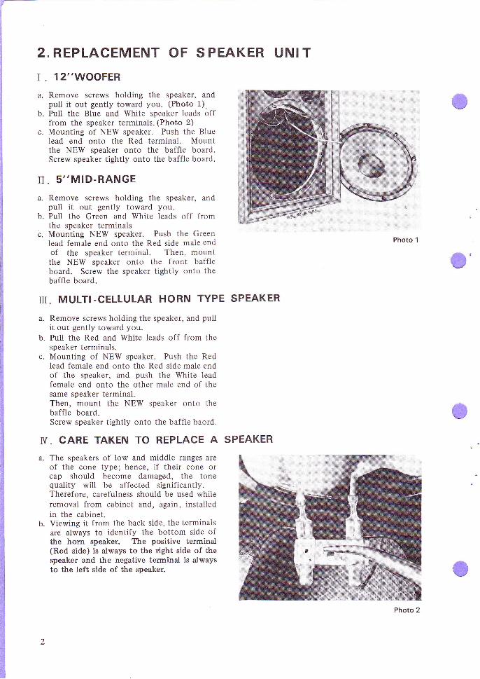
z.REPLACEMENT OF S PEAKER UNI T
r . 12"WOOFER
a. Remove screws holding the speaker, andpull it out gently toward you. (Photo 1),
b. Pull the Blue and White speaker leads offfrom the speaker terminals. (Photo 2)
c. Mounting of NEW speaker. Push the Bluelead end onto the Red terminal. Mountthe NEW speaker onto the baffle board.Screw speaker tightly onto the baffle board.
II. 5''MID-RANGE
a. Remove screws holding the speaker, andpull it out gently toward you.
b. Pull the Green and White leads off fromthe speaker terminals
c. Mounting NEW speaker. Push the Greenlead female end onto the Red side male endof the speaker terminal. Then, mountthe NEW speaker onto the front baffleboard. Screw the speaker tightly onto thebaffle board.
ru. MULTI-CELLULAR HORN TYPE SPEAKER
a. Remove screws holding the speaker, and puilit out gently toward you.
b. Pull the Red and White leads off from thespeaker terminals.
c. Mounting of NEW speaker. Push the Redlead female end onto the Red side male endof the speaker, and push the White leadfemale end onto the other male end of thesame speaker terminal.Then, mount the NEW speaker onto thebaffle board.Screw speaker tightly onto the baffle baord.
V. CARE TAKEN TO REPLACE A SPEAKER
The speakers of low and middle ranges areof the cone type; hence, if their cone orcap should become damaged, the tonequality will be affected significantly.Therefore, carefulness should be used whileremoval from cabinet and, again, installedin the cabinet.Viewing it from the back side, the terminalsare always to identify the bottom side ofthe horn speaker. The positive terminal(Red side) is always to the right side of thespeaker and the negative terminal is alwaysto the left side of the speaker.
Photo 1
C'

3. PARTS IDENTIFICATION
FRONT VIEW
REAR VIEW
TWEETER(YPT-4OsF)
LEVEL CONTROL(Yw te-602-O)
LEVEL CONTROL(Yw te-603-O)
MID-RANGE(Y t 2- to tF)
LATTICE BAFFLE(Yw7s-604-o)
WOOFER(Y3O-6 tF)or (Y3O-7O9F)
INPUT TERMINAL(YK rs-6 r2-B)
INPUT TERMINAL(YKrs-6t2-C)
c'
(BLUE)
(wHrTE)

ACTUAL APPEARANCE OF NETWORK
M, GREENI GREEN
SERVICE PARTS LIST
cs-A7C]0
T+WHITERED andWHITE STRIPET"REDT3WHITE
L,
W*BLUEW WHITE
DESCRIPTION
Woofer
Mid-range
Tweeter
Lattice baffle
Network
lnput terminal (BLUE)
lnput terminal (WHITE)
Knob
Packing case
Level control (High Range)
Level control (Mid .Range)
PART NO.
Y3G61F or Y3O-709F
Y 12-101F
YPT.405F
YWTs-604-0
YW17-618-O
YK15-612-B
YK15-612-C
YA19-621-0
YH35-608-O
YW18-602-0
YW18-603-0
4.
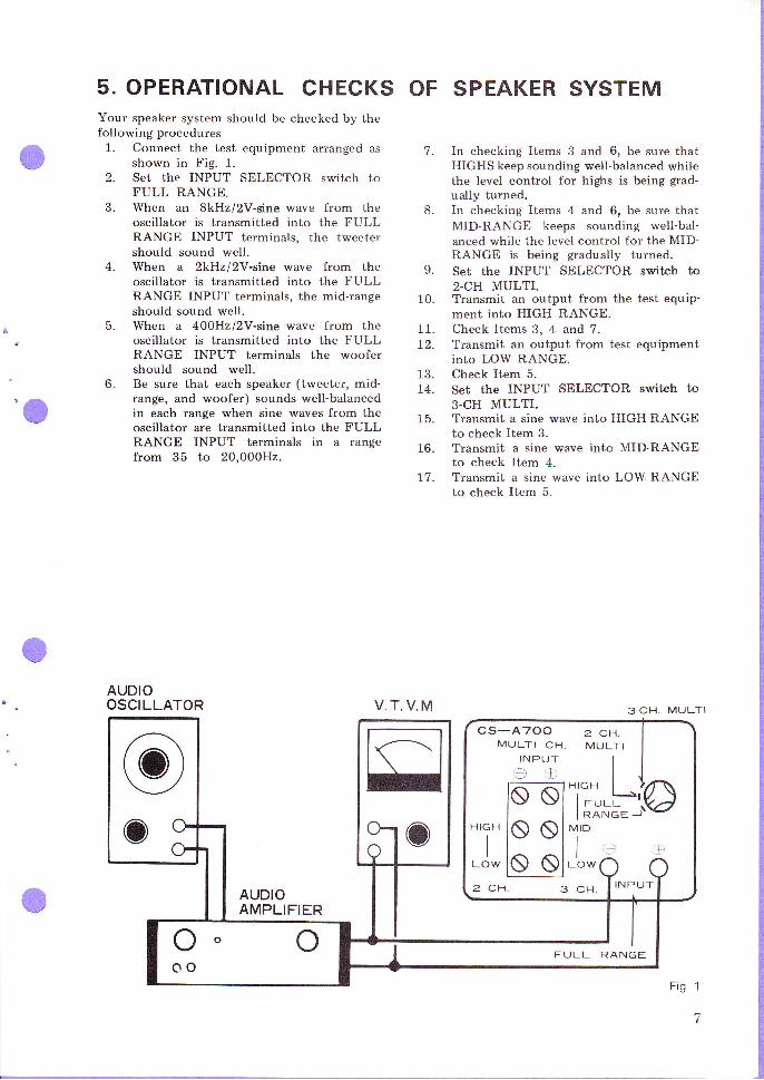
5. OPERATIONAL CHECKSYour speaker system should be checked by thefollowing procedures1. Connect the test equipment ai-ranged as
shown in Fig. 1.2. Set the INPUT SELECTOR switch to
FULL RANGE.o- When an 8kHz/2V-sine wave from the
oscillator is transmitted into the FULLRANGE INPUT terminals, the tweetershould sound well.When a 2kHzl2V-sine wave from theoscillator is transmitted into the FULLRANGE INPUT terminals, the mid-rangeshould sound well.When a 4ooHzl2Y-sine wave from theoscillator is transmitted into the FULLRANGE INPUT terminals the woofershould sound well.Be sure that each speaker (tweeter, mid-range, and woofer) sounds well-balancedin each range when sine waves from theoscillator are transmitted into the FULLRANGE INPUT terminals in a rangefrom 35 to 20,000H2.
AUDIOOSCILLATOR
OF SPEAKER SYSTEM
7. In checking Items 3 and 6, be sure thatHIGHS keep sounding well-balanced whilethe level control for highs is being grad-ually turned,
8. In checking Items 4 and 6, be sure thatMID-RANGE keeps sounding well-bal-anced while the level control for the MID-RANGE is being gtadually turned.
9. SCt thE INPUT SELECTOR SWitCh tO2-CH MULTI.
10. TYansmit an output from the test equip-ment into HIGH RANGE.
11. Check ltems 3, 4 and 7.72. Transmit an output from test equipment
into LOW RANGE.13. Check Item 5.74. Set the INPUT SELECTOR switch to
3.CH MULTI.15. Transmit a sine wave into HIGH RANGE
to check Item 3.TYansmit a sine wave into MID-RANGEto check Item 4.Transmit a sine wave into LOW RANGEto check Item 5.
5.
6.
16.
77.
V.T. V.M 3CH. MULTI
cs-A700MULTI CH.
INPUT,ie
2 C|..,]'.
MULTI
"r"",-L*'l.o
2 CH. s CFr. I INPUT
FULL RANGEooo

I-2
<:
ij'o e
oo
rit
t-
w
\_7
Jrrz;2E
=J>
5E
,''i--=-",
//.6 I
//./t
I /
<t?+
{.o5\t-J-ed\$(1'o
6AOT
E2-o-0-209-tli,ll
I
o'o
t(,soFfoEo+6

6. PACKING PROCEDUREOPERATING INSTRUCTIONS
CORNER PAD
l"PACKING CASE UNIT
(YH3s-6oa-o)SPEAKER SYSTEM ITSELF
CARTON t
SREVICE PAD
VINYL BAG
7

i
ir
i
ii-
lltill
III
PIclN EEFI ELECTFTGIN IC CclFIFGIFIATION"15-5, 4-Chome, Ohmoni- nishi, Ohca-ku, Tokyo, Japan1'IclNEEFI ELECTFIGINICEI U.S.A. clctFIPOFIATIcrN14O Smiih sr., Fanmingdate,Lt.,N.Y. 11735. u.s.,A.FIclNEEFI ELECTFICINIci (EIJFIclPE ) NVFna.k.ijkler 64-68, 20OO A.twentr, Elelgrum
COPYRIGHT O) 1970,9 PRINTED IN JAPAN