© dassault systèmes 1994-2000. all rights reserved.dunet.nicolas.free.fr/catiav5/usinage.pdf ·...
TRANSCRIPT

Prismatic Machining
Preface
What's New?
Getting Started
Entering the Workbench Create a Pocketing Operation Replay Create a Profile Contouring Operation Create a Drilling Operation Assign a Macro Assign a Tool Generate NC Code
Basic Tasks
Milling Operations Axial Machining Operations Auxiliary Operations Part Operation and Manufacturing Program Manufacturing Entities Verification, Simulation and Program Output
Advanced Tasks
Design Changes Set Up and Part Positioning
Workbench Description
Menus Toolbars
Customizing
NC Manufacturing Settings Tools Catalog PP Word Syntaxes NC Documentation Material Simulation Settings
Reference
Tools NC Macros PP Tables and PP Word Syntaxes APT Formats
Glossary
Index

© Dassault Systèmes 1994-2000. All rights reserved.

PrefaceCATIA Prismatic Machining enables you to define and manage NC programs dedicated tomachining parts designed in 3D wireframe or solids geometry using 2.5 axis machiningtechniques.
It offers an easy-to-use and easy-to-learn graphic interface that makes it suitable for shopfloor-oriented use. Moreover, its leading edge technologies together with a tight integrationwith CATIA V5 design methodologies and DELMIA's digital manufacturing environment, fullysatisfy the requirements of office programming. Thus, CATIA Prismatic Machining is a uniquesolution that reconciliates office and shop floor activities.
It is integrated to a Post Processor Access execution engine, allowing the product to cover thewhole manufacturing process from tool trajectory (APT source) to NC Data (ISO format).
This product is particularly adapted for tooling and simple machined parts, and is also an idealcomplement of other manufacturing applications.
CATIA Prismatic Machining offers the following main functions:2.5 axis milling and drilling capabilitiesManagement of tools and tool catalogsFlexible management of the manufacturing program with intuitive and easy-to-learn userinterface based on graphic dialog boxesTight interaction between tool path definition, verification and generationSeamless NC data generation thanks to an integrated Post Processor Access solutionAutomatic shop floor documentation in HTML formatHigh associative level of the manufacturing program ensures productive design changemanagement thanks to the integration with CATIA V5 modeling capabilitiesBased on the Process Product Resources (PPR) model, the manufacturing applicationsare integrated with Digital Process for Manufacturing (DPM).
Certain portions of this product contain elements subject to copyright owned by the following entities:© Copyright LightWork Design Ltd., all rights reserved.© Copyright Deneb Robotics Inc., all rights reserved.© Copyright Cenit, all rights reserved.© Copyright Intelligent Manufacturing Software, all rights reserved.

What's New?Cutter Profile Output New: You can now obtain cutter profile output when generating APT or ISO code for ProfileContouring and Circular Milling operations. Pocketing OperationsNew: Dedicated options are now available for machining Open Pockets.Enhanced: You can now specify operation start and end points for helical machining.Enhanced: You can now constrain the tool to stay on the pocket bottom in transitions betweendomains of pocket. Facing OperationsEnhanced: You can now specify operation start and end points for helical machining. Point to Point OperationsEnhanced: You can now specify approach and retract macros on Point to Point operations. Axial Machining OperationsEnhanced: You can now specify approach, retract and linking macros on all types of axialmachining operations. User-defined Tool RepresentationNew: You can now replace a catalog tool by a user-defined CATPart tool representation. CustomizingEnhanced: Additional options in Tools > Options for NC Manufacturing. Attach Generated NC Output to ProgramNew: You can now attach the generated NC file to the program and display it in text editor. ReplayEnhanced: Visualization of cutter profile trajectory and user-defined tool representation.

Getting StartedBefore getting into the detailed instructions for using CATIA Prismatic Machining, this tutorial isintended to give you a feel of what you can accomplish with the product.
It provides the following step-by-step scenario that shows you how to use some of the keyfunctionalities.
Entering the WorkbenchCreate a Pocketing Operation
Replay the ToolpathCreate a Contouring Operation
Create a Drilling OperationAssign a MacroAssign a Tool
Generate NC Code

Entering the WorkbenchThis first task shows you how to open a part and enter the Prismatic Machining workbench.
1. Select File -> Open then select the GettingStartedPrismaticMachining.CATPart document.
2. Select NC Manufacturing > Prismatic Machining from the Start menu.
The Prismatic Machining workbench appears.
The part is displayed in the Set Up Editor window along with the manufacturing specification tree.
3. Select Manufacturing Program.1 in the tree to make it the current entity.
A program must be current before you can insert program entities such as machining operations,tools and auxiliary commands.

Create a Pocketing OperationThis task shows you how to insert a pocketing operation in the program.
As this operation will use the default tool and options proposed by the program, you just need to specify the geometryto be machined.1. Select the Pocketing icon .
A Pocketing.1 entity along with a default tool is addedto the program.
The small symbol on the Pocketing tree icon means that the operation definition is incomplete.
The Pocketing dialog box appears directly at theGeometry tab page .
The red status light on the tab indicates that you mustselect the pocket geometry in order to create theoperation.
The Geometry page includes an icon representing asimple pocket.
There are several sensitive areas and texts in the iconto help you specify the pocket geometry. Sensitiveareas that are colored red indicate required geometry.
2. Click the red Bottom area in the icon.
The dialog box is reduced allowing you to select thecorresponding part geometry.
3. Select the bottom of the pocket.
The boundary of the selected pocket bottom isproposed as drive element for the operation.
The dialog box reappears.
The bottom and sides of the pocket in the icon are nowcolored green, indicating that the correspondinggeometry is defined for the operation. The tab status isnow green .
4. Click OK to create the operation.


Replay the Tool PathThis task shows you how to replay the tool path of the pocketing operation.
1. Select the pocketing operation in thetree then select the Replay Tool Pathicon .
The Replay dialog box appears.2. Choose the Point by Point replay mode
by means of the drop down icon .
You can set the number of points to bereplayed at each step of the replay bymeans of the combo.
3. Click the button to position the toolat the start point of the operation.
4. Click the button to start the replayand continue to click that button tomove the tool along the computedtrajectory.
5. Click OK to quit the replay mode.

Create a Profile Contouring OperationThis task shows you how to insert a profile contouring operation in the program.
Make sure that the pocketing operation is the current entity in the program.
1. Select the Profile Contouring icon .
The Profile Contouring dialog box appears directly at
the Geometry page .
2. Click the Bottom: Hard text in the sensitive icon toswitch the type of bottom to Soft.
3. Click the Bottom plane then select the correspondingpart geometry (that is, the underside of the part).
The closed external contour of the bottom isproposed as Guide element for the operation.
4. If needed, to set the tool axis orientation, double click the Tool Axis symbol then click the Reverse Directionbutton.
Make sure that the arrow on the Guide element is pointing away from the part.
5. Click the Top plane in the icon, then select the corresponding part geometry.6. Double click Offset on Contour in the icon.
Set this value to 1mm in the Edit Parameter dialogbox and click OK.

7. Select the Strategy tab page and set theparameters as shown.
8. Click Preview in the dialog box to request that the program verifies the parameters that you have specified.
A message box appears giving feedback about this verification. 9. Click Replay in the dialog box to visually check the operation's tool path.
10. Click OK to create the operation.

Create a Drilling OperationThis task shows you how to insert a drilling operation in the program.
1. Select the Drilling icon .
The Drilling dialog box appears directly at the Geometry page .The program is updated toinclude a Drilling operation.
The Drilling dialog boxappears.
2. Select the red hole depthrepresentation in the sensitiveicon.
The Manufacturing Viewdialog box appears to helpyou specify the pattern ofholes to be machined.
3. Select the cylindrical featureof the first hole.
4. Select the second holefeature, then double click toend hole selection.
The Drilling dialog boxreplaces the ManufacturingView dialog box.
The icon is updated withgeometric information aboutthe first selected hole of thepattern.

5. Double click the Jumpdistance parameter in thesensitive icon, then enter avalue of 5mm in the EditParameter dialog box.
6. Click Replay to replay the operation as described previously. Click OK to return to the Drilling dialog box.
7. Click OK to create the Drilling operation in the program.

Assign a MacroThis task shows you how to assign a circular approach macro to the Profile Contouring operation.
1. Double click the Profile Contouring operation in theprogram, then select the Macro tab page .
2. Click the Approach checkbox.
3. Click the Circular Approach icon.
The icon representing the approach motion is displayed.
Default values are displayed on the individual paths ofthe macro.
4. Double click the circular path of the macro.
A dialog box appears allowing you to specify the desiredparameters of the circular path.
5. Enter values in the dialog box as shown and click OK.
6. Click Replay in the Profile Contouring dialog box to verifythe approach motion.Click OK to return to the Profile Contouring dialog box.

7. Click OK to assign the specified macro to the operation.

Assign a ToolThis task shows you how to assign another tool to an operation.
1.Double click the Profile Contouring operation in the program, then select the Tool tab page .
2. Enter a name of the new tool (for example, 16mm Flat Milling Tool).3. Double click the D (nominal diameter) parameter in the
icon, then enter 16mm in the Edit Parameter dialog box.
The tool icon is updated to take the new value intoaccount.
4. Double click the Rc (corner radius) parameter in the icon,then enter 0mm in the Edit Parameter dialog box.
Set the db (body diameter) parameter to 24mm in thesame way.
The Tool number is set to 2.
5. Click OK to accept the new tool.
The program is automatically updated.
You can modify the tools of the other operations in the same way. For example, you may want to replace the EndMill by a Drill in the Drilling operation.


Generate NC CodeThis task shows you how to generate the NC code from the program.
1. Use the right mouse key on theManufacturing Program.1 entity in the treeto select Generate NC Code Interactively.
The Save NC File dialog box appears.
2. Select the folder where you want the file tobe saved and specify the name of the file.
3. Click Save to create the APT file.
Here is an extract from the Apt source file that will be generated:$$ -----------------------------------------------------------------$$ Generated on Tue May 23 15:20:47 2000$$ -----------------------------------------------------------------$$ Manufacturing Program.1$$ Part Operation.1$$*CATIA0$$ Manufacturing Program.1$$ 1.00000 0.00000 0.00000 0.00000$$ 0.00000 1.00000 0.00000 0.00000$$ 0.00000 0.00000 1.00000 0.00000PARTNO PART TO BE MACHINEDCOOLNT/ONCUTCOM/OFFPPRINT OPERATION NAME : Tool Change.1$$ Start generation of : Tool Change.1PPRINT TOOL = T1 End Mill D 10CUTTER/ 10.000000, 2.000000, 3.000000, 2.000000, 0.000000,$0.000000,100.000000TOOLNO/1, 10.000000TPRINT/T1 End Mill D 10LOADTL/1TLAXIS/ 0.000000, 0.000000, 1.000000RAPIDGOTO/ 0.00000, 0.00000, 100.00000$$ End of generation of : Tool Change.1PPRINT OPERATION NAME : Pocketing.1$$ Start generation of : Pocketing.1FEDRAT/ 1000.0000,MMPMSPINDL/ 70.0000,RPM,CLWGOTO/ 35.36644, 2.50000, 5.00000GOTO/ 42.50000, 2.50000, 5.00000...GOTO/ -15.00000, 35.00000, 5.00000GOTO/ 35.61644, 35.00000, 5.00000$$ End of generation of : Pocketing.1PPRINT OPERATION NAME : Tool Change.2$$ Start generation of : Tool Change.2PPRINT TOOL = 16mm Flat Milling ToolCUTTER/ 16.000000, 0.000000, 8.000000, 0.000000, 0.000000,$0.000000,100.000000TOOLNO/2, 16.000000

TPRINT/16mm Flat Milling ToolLOADTL/2RAPIDGOTO/ 0.00000, 0.00000, 100.00000$$ End of generation of : Tool Change.2PPRINT OPERATION NAME : Profile Contouring.1$$ Start generation of : Profile Contouring.1FEDRAT/ 300.0000,MMPMSPINDL/ 70.0000,RPM,CLWGOTO/ -69.00000, 40.00000, 46.00000...GOTO/ -69.00000, 50.00000, 16.00000FEDRAT/ 1000.0000,MMPMGOTO/ -68.67819, 53.48215, 16.00000GOTO/ -67.72364, 56.84635, 16.00000...GOTO/ -68.92036, -51.73784, 0.00000GOTO/ -69.00000, 50.00000, 0.00000$$ End of generation of : Profile Contouring.1PPRINT OPERATION NAME : Tool Change.3$$ Start generation of : Tool Change.3PPRINT TOOL = 9mm DrillCUTTER/ 10.000000, 0.000000, 5.000000, 2.886751, 30.000000,$0.000000,100.000000TOOLNO/3, 10.000000TPRINT/9mm DrillLOADTL/3RAPIDGOTO/ 0.00000, 0.00000, 100.00000$$ End of generation of : Tool Change.3PPRINT OPERATION NAME : Drilling.1$$ Start generation of : Drilling.1LOADTL/3,1SPINDL/ 70.0000,RPM,CLWRAPIDGOTO/ -40.00000, 30.00000, 25.00000CYCLE/DRILL, 10.000000, 1.000000, 1000.000000,MMPMGOTO/ -40.00000, 30.00000, 20.00000GOTO/ -40.00000, -30.00000, 20.00000CYCLE/OFF$$ End of generation of : Drilling.1SPINDL/OFFREWIND/0END

Basic TasksThe basic tasks you will perform in the Prismatic Machining workbench involve creating, editingand managing machining operations and other entities of the CATIA manufacturing process.
Milling OperationsAxial Machining Operations
Auxiliary OperationsPart Operation and Manufacturing Program
Managing Manufacturing EntitiesVerification, Simulation and Program Output

Milling OperationsThe tasks in this section show you how to create milling operations in your manufacturing program.
Create a Pocketing Operation: Select the Pocketing icon then select the geometry of the pocket to be machinedand specify the tool to be used. Specify machining parameters, feeds and speeds, and NC macros as needed.
A Pocketing operation can be created for machining:Closed pocketsTool machines the area delimited by hard boundariesOpen pocketsTool machines the area that has a least one soft boundary.
Create a Facing Operation: Select the Facing icon then select the geometry to be machined and specify the toolto be used. Specify machining parameters, feeds and speeds, and NC macros as needed.Create a Profile Contouring Operation: Select the Profile Contouring icon then select the geometry to bemachined and specify the tool to be used. Specify machining parameters, feeds and speeds, and NC macros asneeded.
A Profile Contouring operation can be created for machining:Between two planesTool follows contour between top and bottom planes while respecting user-defined geometry limitationsand machining strategy parameters.Between two curves Tool follows trajectory defined by top and bottom guide curves while respecting user-defined geometrylimitations and machining strategy parameters.Between a curve and surfacesTool follows trajectory defined by a top guide curve and bottom surfaces while respecting user-definedgeometry limitations and machining strategy parameters.
Create a Point to Point Operation: Select the Point to Point icon then select the geometry to be machined andspecify the tool to be used. Specify machining parameters and feeds and speeds as needed.

Create a Pocketing Operation for Machining Closed Pockets
This task shows how to insert a Pocketing operation in the program when the pocket to be machined compriseshard boundaries only (that is, a closed pocket).
To create the operation you must define:the Pocketing mode as Closed Pocketthe geometry of the pocket to be machined
the tool that will be used
the parameters of the machining strategy
the feedrates and spindle speeds
the macros (transition paths) .
Open the PrismaticMilling01.CATPart document, then select NC Manufacturing > Prismatic Machining from theStart menu. Make the Manufacturing Program current in the specification tree. 1. Select the Pocketing icon .
A Pocketing entity along with a default tool isadded to the program.The Pocketing dialog box appears directly at theGeometry tab page .
This tab page includes a sensitive icon to helpyou specify the geometry to be machined.
The bottom and flanks of the icon are colored redindicating that this geometry is required fordefining the pocket.All other pocket geometry is optional.
Make sure that the Pocketing mode is set toClosed Pocket.
2. Click the red Bottom in the icon then select thedesired pocket bottom in the 3D window.
The pocket boundary is automatically deduced bythe program. This is indicated by the highlightedDrive elements.
The bottom and flanks of the icon are nowcolored green indicating that this geometry is nowdefined.

3. Click the Top Plane in the icon then select thedesired top element in the 3D window.
4. Set the following offsets:1.5mm on boundary0.25mm on bottom.
You can select an inner point and a border point as preferential start and end positions for the operation.This allows better control for optimizing the program according to the previous and following operations.
5. Select the Strategy tab page to specify:
tool path styleradial strategy parametersaxial strategy parameters.
You can use the More button to specify additionalparameters such as:
machining tolerance thickness values for pocket finishinghigh speed milling parameters.
For a pocket with several domains, you can select Always stay on bottom to avoid unnecessary linkingtransitions. This option forces the tool to remain in contact with the pocket bottom when moving from onedomain to another. In this case, you can also select Inward/outward mix to authorize changing from one toolpath style fromone pocket domain to another. A tool is proposed by default when you want to create a machining operation. If the proposed tool is notsuitable, just select the Tool tab page to specify the tool you want to use.
This is described in Edit the Tool of an Operation.6. Select the Feeds and Speeds tab page to specify the feedrates and spindle speeds for the operation.

7. Select the Macros tab page to specify theoperation's transition paths (approach and retractmotion, for example).
Select the Approach and RetractcheckboxesSelect an Approach macro icon to specifythe desired type of approach motion(linear, for example). A sensitive iconappears with a representation of themacro.Double click the distance parameter in thesensitive icon and enter the desired valuein the pop-up dialog box.Repeat this procedure to specify theRetract motion.
See Define Macros of an Operation for anotherexample of specifying transition paths on amachining operation.
Before accepting the operation, you should check its validity by replaying the tool path.
8. Click OK to create the operation.

Create a Pocketing Operationfor Machining Open Pockets
This task shows how to insert a Pocketing operation in the program when the pocket to be machined comprises atleast one soft boundary (that is, an open pocket).
To create the operation you must define:the Pocketing mode as Open Pocketthe geometry of the pocket to be machined
the tool that will be used
the parameters of the machining strategy
the feedrates and spindle speeds
the macros (transition paths) .
Open the PrismaticMilling02.CATPart document, then select NC Manufacturing > Prismatic Machining from the Startmenu. Make the Manufacturing Program current in the specification tree. 1. Select the Pocketing icon .
A Pocketing entity along with a default tool isadded to the program.The Pocketing dialog box appears directly at theGeometry tab page .
This tab page includes a sensitive icon to help youspecify the geometry to be machined.
The bottom and flanks of the icon are colored redindicating that this geometry is required fordefining the pocket.All other pocket geometry is optional.
Make sure that the Pocketing mode is set to OpenPocket.
2. Click the red Bottom in the icon then select thedesired pocket bottom in the 3D window.
The pocket boundary is automatically deduced bythe program. This is indicated by the highlightedDrive elements.
Hard boundaries are shown by full lines and softboundaries by dashed lines.
For edge selection only, you can change aboundary segment from hard to soft (or from softto hard) by selecting the corresponding edge.
The bottom and flanks of the icon are now coloredgreen indicating that this geometry is now defined.

3. Click the Top Plane in the icon then select thedesired top element in the 3D window.
4. Set the following offsets:1.5mm on boundary0.25mm on bottom.
You can select an inner point and a border point as preferential start and end positions for the operation. Thisallows better control for optimizing the program according to the previous and following operations.
5. Select the Strategy tab page to specify:
tool path styleradial strategy parametersaxial strategy parameters.
You can use the More button to specify additionalparameters such as:
machining tolerance thickness values for pocket finishinghigh speed milling parameters.
For a pocket with several domains, you can select Always stay on bottom to avoid unnecessary linkingtransitions. This option forces the tool to remain in contact with the pocket bottom when moving from one domainto another. In this case, you can also select Inward/outward mix to authorize changing from one toolpath style from onepocket domain to another. A tool is proposed by default when you want to create a machining operation. If the proposed tool is not suitable,just select the Tool tab page to specify the tool you want to use.
This is described in Edit the Tool of an Operation.6. Select the Feeds and Speeds tab page to specify the feedrates and spindle speeds for the operation.

7. Select the Macros tab page to specify theoperation's transition paths (approach and retractmotion, for example).
Select the Approach and RetractcheckboxesSelect an Approach macro icon to specifythe desired type of approach motion (linear,for example). A sensitive icon appears witha representation of the macro.Double click the distance parameter in thesensitive icon and enter the desired valuein the pop-up dialog box.Repeat this procedure to specify theRetract motion.
See Define Macros of an Operation for anotherexample of specifying transition paths on amachining operation.
Before accepting the operation, you should check its validity by replaying the tool path.
8. Click OK to create the operation.

Create a Facing OperationThis task shows how to insert a Facing operation in the program.
To create the operation you must define:the geometry to be machined
the tool that will be used
the parameters of the machining strategy
the feedrates and spindle speeds
the macros (transition paths) .
Open the PrismaticMilling01.CATPart document, then select NC Manufacturing > Prismatic Machining from theStart menu. Make the Manufacturing Program current in the specification tree. 1. Select the Facing icon .
A Facing entity along with a default tool isadded to the program.The Facing dialog box appears directly at theGeometry tab page .
This tab page includes a sensitive icon to helpyou specify the geometry to be machined.The part bottom and flanks in the icon arecolored red indicating that this geometry isrequired for defining the operation.All other geometry is optional.
2. Click the red Bottom in the icon then select theunderside of the part in the 3D window.
The part boundary is automatically deduced bythe program. This is indicated by the highlightedDrive elements.The bottom and flanks of the icon are nowcolored green indicating that this geometry isnow defined.You can select start and end points as preferential start and end positions on the operation. This allowsbetter control for optimizing the program according to the previous and following operations.
3. Select the Strategy tab page to specify:
toolpath styleradial strategy parameters.
You can use the More button to specifyadditional parameters such as:
machining tolerance thickness values for finishingaxial strategy parametershigh speed milling parameters.

4. Select the Tool tab page to replace the default tool by a more suitable one.
5. Select the Face Mill icon.
A 50mm diameter face mill is proposed. You can adjust the parameters as required.
See Edit the Tool of an Operation for more information about selecting tools.6. Select the Feeds and Speeds tab page to specify the feedrates and spindle speeds for the operation.
7. Select the Macros tab page to specify areturn macro, which is necessary for the OneWay mode.
Select the Return in a Level checkbox.Select one of the macro icons to specifythe desired type of approach motion(linear, for example). A sensitive iconappears with a representation of thepath.Double click the distance parameter inthe sensitive icon and enter the desiredvalue in the pop-up dialog box.Repeat this procedure to specify theretract motion.
See Define Macros of an Operation for anotherexample of specifying transition paths on amachining operation.
Before accepting the operation, you should check its validity by replaying the tool path.
8. Click OK to create the operation.

In this scenario the operation used the default starting point (that is, the origin of the absolute axis system).
If you want to define a different starting point, you can click the starting point symbol in the sensitive icon thenselect a point.
Please note that the exact position of operation's starting point may be different from your selected point. Theprogram will choose the nearest point from a number of possible starting positions.

Create a Profile Contouring OperationBetween Two Planes
This task shows how to insert a 'Between Two Planes' Profile Contouring operation in the program.
To create the operation you must define:the Contouring mode as Between two planesthe geometry to be machined
the tool that will be used
the parameters of the machining strategy
the feedrates and spindle speeds
the macros (transition paths) .
Open the PrismaticMilling01.CATPart document, then select the desired NC Manufacturing workbench from theStart menu. Make the Manufacturing Program current in the specification tree. 1. Select the Profile Contouring icon .
The Profile Contouring dialog box appears directlyat the Geometry tab page . This page includes a sensitive icon to help youspecify the geometry to be machined.
Right click the Contouring mode text and selectBetween Two Planes.The part bottom and flanks in the icon are coloredred indicating that this geometry is required fordefining the operation.All other geometry is optional.
2. Click the red bottom in the icon, then select theunderside of the part in the 3D window.
3. Set the Bottom type to Soft by clicking the text, thenset the Offset on Bottom to -5mm.
4. Click the red flank in the icon, then select the profilealong the front edge of the part in the 3D window.
5. Click the First Limit in the icon, then select thehorizontal edge at one end of the contour profile inthe 3D window.
6. Click the Second Limit in the icon, then select thehorizontal edge at the other end of the contourprofile in the 3D window.
7. Click the check element in the icon, then select thetop face of the green fixture in the 3D window.The bottom, guide, limit and check elements of the icon are now colored green indicating that this geometryis now defined. These are also indicated on the part.

8. Select the Strategy tab page to specify theparameters of the machining strategy as follows:
One way tool path styleRadial strategy: number of paths = 1Axial strategy: number of levels = 1.
You can use the More button to access additionalparameters such as machining tolerance andthickness values for finishing.You can choose between the standard tip output and a cutter profile output by means of the Output styleoption. If a cutter profile style is selected, both the tip and cutter profile will be visualized during tool path replay. The cutter profile output allows easier tool compensation to be done on the shop floor. A tool is proposed by default when you want to create a machining operation. If the proposed tool is notsuitable, just select the Tool tab page to specify the tool you want to use.
This is described in Edit the Tool of an Operation.9. Select the Feeds and Speeds tab page to specify the feedrates and spindle speeds for the operation.
10. Check the validity of the operation by replaying the tool path.
The specified operation uses a default linking macro to avoid collision with the selected fixture.
You can optimize the linking macro and add approach and retract macros to the operation in the Macrostab page . This is described in Define Macros of a Milling Operation.
11. Click OK to create the operation.


Create a Profile Contouring OperationBetween Two Curves
This task shows how to insert a 'Between Two Curves' Profile Contouring operation in the program.
To create the operation you must define:the Contouring mode as Between Two Curvesthe geometry to be machined
the tool that will be used
the parameters of the machining strategy
the feedrates and spindle speeds
the macros (transition paths) .
Open the PrismaticMilling02.CATPart document, then select the desired NC Manufacturing workbench from the Startmenu. Make the Manufacturing Program current in the specification tree. 1. Select the Profile Contouring icon .
The Profile Contouring dialog box appears directly atthe Geometry tab page . This page includes a sensitive icon to help you specifythe geometry to be machined.
Right click the Contouring mode text and selectBetween Two Curves.The top guiding curve in the icon is colored redindicating that this geometry is required for definingthe operation.All other geometry is optional.
2. Click the top guiding curve in the icon, then select thetop edge of the part in the 3D window.
3. If needed, set offsets on the geometric elements.4. Click the bottom guiding curve in the icon, then select
bottom edge of the part in the 3D window.5. Click the first relimiting element in the icon, then select
a vertical edge at one end of the part in the 3Dwindow.
6. Click the second relimiting element in the icon, thenselect the vertical edge at the other end of the contourprofile in the 3D window.The guide and limit elements of the icon are now colored green indicating that this geometry is now defined.These are also indicated on the part.

7. Select the Strategy tab page to specify theparameters of the machining strategy as follows:
Zig Zag tool path styleRadial strategy: number of paths = 1Axial strategy: number of levels = 3.
You can use the More button to access additionalparameters such as machining tolerance andthickness values for finishing.A tool is proposed by default when you want to create a machining operation. If the proposed tool is notsuitable, just select the Tool tab page to specify the tool you want to use.
This is described in Edit the Tool of an Operation.8. Select the Feeds and Speeds tab page to specify the feedrates and spindle speeds for the operation.
9. Check the validity of the operation by replaying the tool path.
You can add approach and retract motions to the operation in the Macros tab page . This is described inDefine Macros of an Operation.
10. Click OK to create the operation.


Create a Profile Contouring OperationBetween a Curve and Surfaces
This task shows how to insert a 'Between Curve and Surfaces' Profile Contouring operation in the program.
To create the operation you must define:the Contouring mode as Between Curve and Surfacesthe geometry to be machined
the tool that will be used
the parameters of the machining strategy
the feedrates and spindle speeds
the macros (transition paths) .
Open the the PrismaticMilling02.CATPart document, then select the desired NC Manufacturing workbench from theStart menu. Make the Manufacturing Program current in the specification tree. 1. Select the Profile Contouring icon .
The Profile Contouring dialog box appearsdirectly at the Geometry tab page . This page includes a sensitive icon to help youspecify the geometry to be machined.
Right click the Contouring mode text and selectBetween Curve and Surfaces.The top guiding curve and part bottom in theicon are colored red indicating that thisgeometry is required for defining the operation.All other geometry is optional.
2. Click the red bottom in the icon, then select thebottom surface of the part in the 3D window.
3. If needed, set offsets on the geometricelements.
4. Click the top guiding curve in the icon, thenselect the top edge of the part in the 3D window.
5. Click the first relimiting element in the icon, thenselect a vertical edge at one end of the part inthe 3D window.
6. Click the second relimiting element in the icon,then select the vertical edge at the other end ofthe contour profile in the 3D window.The guide and limit elements of the icon are now colored green indicating that this geometry is now defined.These are also indicated on the part.

7. Select the Strategy tab page to specifythe parameters of the machining strategy asfollows:
Zig Zag tool path styleRadial strategy: number of paths = 3Axial strategy: number of levels = 3.
You can use the More button to accessadditional parameters such as machiningtolerance and thickness values for finishing.A tool is proposed by default when you want to create a machining operation. If the proposed tool is not suitable,just select the Tool tab page to specify the tool you want to use.
This is described in Edit the Tool of an Operation.8. Select the Feeds and Speeds tab page to specify the feedrates and spindle speeds for the operation.
9. Check the validity of the operation by replaying the tool path.
You can add approach and retract motions to the operation in the Macros tab page . This is described inDefine Macros of an Operation.
10. Click OK to create the operation.


Create a Point to Point OperationThis task shows how to insert a Point to Point operation in the program.
To create the operation you must define:the geometry to be machined
the tool that will be used
the parameters of the machining strategy
the feedrates and spindle speeds
the macros (transition paths) .
Open the PrismaticMilling01.CATPart document, then select NC Manufacturing > Prismatic Machining from theStart menu. Make the Manufacturing Program current in the specification tree.
1. Select the Point to Point icon .
A Point to Point entity along with a default tool isadded to the program.
The Point to Point dialog box appears directly atthe Geometry tab page . This page includes a sensitive iconrepresenting a simple point-to-point tool path.
2. Click the red point-to-point tool pathrepresentation, then select the desired points tobe machined in the 3D window.
You can select the edges of the holes on theunderside of the part.
Just double-click to end point selection.
By selecting a circle, its center is taken as thepoint to machine.
Points of an associated sketch could also havebeen selected.
Points can be inserted or removed by means ofthe contextual menu.
3. If needed, double click the sensitive text in theicon to specify an offset.
4. Define the tool axis direction by first selectingthe axis representation in the sensitive icon thenspecifying the direction in the dialog box thatappears.

5. Select the Strategy tab page to specify machining parameters.Note that only Tool compensation is available for this operation.
6. Select the Tool tab page to replace the default tool by a more suitable one.
7. Select the Face Mill icon.
A 50mm diameter face mill is proposed. You can adjust the parameters as required.
See Edit the Tool of an Operation for more information about selecting tools.8. Select the Feeds and Speeds tab page to specify the feedrates and spindle speeds for the
operation.9. If you want to specify approach and retract motion for the operation, select the Macros tab page to
specify the desired transition paths.
The general procedure for this is described in Define Macros of an Operation.Before accepting the operation, you should check its validity by replaying the tool path.
10. Click OK to create the operation.
You can use the contextual menu commands to insert or remove points and to assign local feedrates.

Axial Machining OperationsThe tasks in this section show you how to create axial machining operations in your manufacturing program.
Spot Drilling OperationCreate a Spot Drilling Operation: Select the Spot Drilling icon then select the hole or hole pattern to be machinedand specify the tool to be used. Specify machining strategy parameters, macros and feeds and speeds asneeded.
Drilling OperationsCreate a Drilling Operation: Select the Drilling icon then select the hole or hole pattern to be machined and specifythe tool to be used. Specify machining strategy parameters, macros and feeds and speeds as needed.Create a Drilling Dwell Delay Operation: Select the Drilling Dwell Delay icon then select the hole or hole pattern tobe machined and specify the tool to be used. Specify machining strategy parameters, macros and feeds andspeeds as needed.Create a Drilling Deep Hole Operation: Select the Drilling Deep Hole icon then select the hole or hole pattern tobe machined and specify the tool to be used. Specify machining strategy parameters, macros and feeds andspeeds as needed.Create a Drilling Break Chips Operation: Select the Drilling Break Chips icon then select the hole or hole patternto be machined and specify the tool to be used. Specify machining strategy parameters, macros and feeds andspeeds as needed.
Hole Finishing OperationsCreate a Reaming Operation: Select the Reaming icon then select the hole or hole pattern to be machined andspecify the tool to be used. Specify machining strategy parameters, macros and feeds and speeds as needed.Create a Counterboring Operation: Select the Counterboring icon then select the hole or hole pattern to bemachined and specify the tool to be used. Specify machining strategy parameters, macros and feeds and speedsas needed.
Boring OperationsCreate a Boring Operation: Select the Boring icon then select the hole or hole pattern to be machined and specifythe tool to be used. Specify machining strategy parameters, macros and feeds and speeds as needed.Create a Boring Spindle Stop Operation: Select the Boring Spindle Stop icon then select the hole or hole patternto be machined and specify the tool to be used. Specify machining strategy parameters, macros and feeds andspeeds as needed.Create a Boring and Chamfering Operation: Select the Boring and Chamfering icon then select the hole or holepattern to be machined and specify the tool to be used. Specify machining strategy parameters, macros and feedsand speeds as needed.Create a Back Boring Operation: Select the Back Boring icon then select the hole or hole pattern to be machinedand specify the tool to be used. Specify machining strategy parameters, macros and feeds and speeds asneeded.
Threading OperationsCreate a Tapping Operation: Select the Tapping icon then select the hole or hole pattern to be machined andspecify the tool to be used. Specify machining strategy parameters, macros and feeds and speeds as needed.Create a Reverse Threading Operation: Select the Reverse Threading icon then select the hole or hole pattern tobe machined and specify the tool to be used. Specify machining strategy parameters, macros and feeds andspeeds as needed.Create a Thread without Tap Head Operation: Select the Thread without Tap Head icon then select the hole orhole pattern to be machined and specify the tool to be used. Specify machining strategy parameters, macros andfeeds and speeds as needed.
Countersinking and Chamfering OperationsCreate a Countersinking Operation: Select the Countersinking icon then select the hole or hole pattern to bemachined and specify the tool to be used. Specify machining strategy parameters, macros and feeds and speedsas needed.

Create a Chamfering Two Sides Operation: Select the Chamfering Two Sides icon then select the hole or holepattern to be machined and specify the tool to be used. Specify machining strategy parameters, macros and feedsand speeds as needed.
T-Slotting and Circular MillingCreate a T-Slotting Operation: Select the T-Slotting icon then select the hole or hole pattern to be machined andspecify the tool to be used. Specify machining strategy parameters, macros and feeds and speeds as needed.Create a Circular Milling Operation: Select the Circular Milling icon then select the hole or hole pattern to bemachined and specify the tool to be used. Specify machining strategy parameters, macros, and feeds and speedsas needed.

Create a Spot Drilling OperationThis task shows how to insert a Spot Drilling operation in the program.
To create the operation you must define:the geometry of the holes to be machined
the tool that will be used
the parameters of the machining strategy
the feedrates and spindle speeds
the macros (transition paths) .
Open the HoleMakingOperations.CATPart document, then select the desired NC Manufacturing workbench fromthe Start menu.
Make the Manufacturing Program current in the specification tree.
1. Select the Spot Drilling icon .
A Spot Drilling entity along with a default tool is added to the program.
The Spot Drilling dialog box appears directly at the Geometry tab page . This tab page includes an iconrepresenting a simple hole. There are several hot spots in the icon.
2. Select red hole depth representation, then select the points to be spot drilled. You can do this by selecting the circular REDGEs of holes.In this case, the circle centers are taken as the points to be spot drilled.Just double click to end your selections.
3. If needed select a tool axis direction.

4. Select the Strategy tab page to specify thefollowing machining parameters:
approach clearancedepth mode: by diameterThe diameter value used is the onespecified in the geometry tab page.dwellcompensation number depending onthose available on the tool.
The other parameters are optional in this case.
A tool is proposed by default when you want to create a machining operation.
If the proposed tool is not suitable, just select the Tool tab page to specify the tool you want to use.
This is described in Edit the Tool of an Operation.5. Select the Feeds and Speeds tab page to specify the feedrates and spindle speeds for the operation.
Note that in the tool path represented in the strategy page, tool motion is as follows:Motion at machining feedrate from 1 to 2Dwell for the specified durationRetract at retract feedrate from 2 to 3.
6. If you want to specify approach and retract motion for the operation, select the Macros tab page tospecify the desired transition paths.
The general procedure for this is described in Define Macros of an Axial Machining Operation.
Before accepting the operation, you should check its validity by replaying the tool path.
7. Click OK to create the operation.Example of output
If your PP table is customized with the following statement for Spot Drilling operations:CYCLE / SPDRL, %MFG_TOTAL_DEPTH, %MFG_FEED_MACH_VALUE, &MFG_FEED_UNIT, %MFG_CLEAR_TIP, DWELL, %MFG_DWELL_REVOL
A typical NC data output is as follows:CYCLE/SPDRL, 25.000000, 500.000000, MMPM, 5.000000, DWELL, 3
However, if the Syntax Used option is set to No for NC Output generation, then GOTO points will begenerated instead of this PP word syntax.


Create a Drilling OperationThis task shows how to insert a Drilling operation in the program.
To create the operation you must define:the geometry of the holes to be machined
the tool that will be used
the parameters of the machining strategy
the feedrates and spindle speeds
the macros (transition paths) .
Open the HoleMakingOperations.CATPart document, then select the desired NC Manufacturing workbench fromthe Start menu.
Make the Manufacturing Program current in the specification tree.
1. Select the Drilling icon .
A Drilling entity along with a default tool is added to the program.
The Drilling dialog box appears directly at the Geometry tab page . This tab page includes a sensitiveicon to help you specify the geometry of the hole or hole pattern to be machined.
2. Select the red hole depth representation then select 4 hole features as shown below.Just double click to end your selections.
The sensitive icon is updated with the following information:depth and diameter of the first selected featurehole extension type: through holenumber of points to machine.
3. If needed, you can define the tool axis direction by first selecting the axis representation in the sensitive iconthen specifying the direction by means of the dialog box that appears.
4. If needed, you can define a clearance by first double clicking the Jump Distance in the sensitive icon thenspecifying a value in the Edit Parameter dialog box that appears.

Note that the jump distance allows an extra clearance for moving in Rapid motion between the holes to bedrilled whenever this distance is greater than the approach clearance.For example, for an approach clearance of 2.5mm and a jump distance of 10mm, the extra clearance is7.5mm.
You can also locally specify entry and exit distances at individual points in a hole pattern using the contextualmenu (right click the pattern point).
The contextual menu also allows you to skip pattern points and choose the start point for the pattern.5. Select the Strategy tab page to specify the
following machining parameters:Approach clearanceDepth mode: by tipThe depth value used is the one used in theGeometry tab page.Breakthrough distanceCompensation number depending on thoseavailable on the tool.
The other parameters are optional in this case.
A tool is proposed by default when you want to create a machining operation.
If the proposed tool is not suitable, just select the Tool tab page to specify the tool you want to use.
Remember that you can make use of the hole diameter found on the selected hole feature to select anappropriate tool.
This is described in Edit the Tool of an Operation.6. Select the Feeds and Speeds tab page to specify the feedrates and spindle speeds for the operation.
Note that in the Drilling tool path represented in the strategy page, tool motion is as follows:machining feedrate from 1 to 2retract or rapid feedrate from 2 to 3.
7. If you want to specify approach and retract motion for the operation, select the Macros tab page tospecify the desired transition paths.
The general procedure for this is described in Define Macros of an Axial Machining Operation.
Before accepting the operation, you should check its validity by replaying the tool path.
8. Click OK to create the operation.

Example of output
If your PP table is customized with the following statement for Drilling operations:CYCLE/DRILL, %MFG_TOTAL_DEPTH, %MFG_FEED_MACH_VALUE, &MFG_FEED_UNIT, %MFG_CLEAR_TIP
A typical NC data output is as follows:CYCLE/DRILL, 38.500000, 500.000000, MMPM, 2.500000
However, if the Syntax Used option is set to No for NC Output generation, then GOTO points will be generatedinstead of this PP word syntax.

Create a Drilling Dwell Delay OperationThis task shows how to insert a Drilling Dwell Delay operation in the program.
To create the operation you must define:the geometry of the holes to be machined
the tool that will be used
the parameters of the machining strategy
the feedrates and spindle speeds
the macros (transition paths) .
Open the HoleMakingOperations.CATPart document, then select the desired NC Manufacturing workbench fromthe Start menu.
Make the Manufacturing Program current in the specification tree.1. Select the Drilling Dwell Delay icon .
A Drilling Dwell Delay entity along with a default tool is added to the program.
The Drilling Dwell Delay dialog box appears directly at the Geometry tab page . This tab page includesa sensitive icon to help you specify the geometry of the hole or hole pattern to drill.
2. Select the red hole depth representation then select the hole feature as shown.Just double click to end your selection.
The sensitive icon is updated with thefollowing information:
depth and diameter of the selectedholehole extension type: blind.
3. If needed, you can define the tool axis direction by first selecting the axis representation in the sensitive iconthen specifying the direction by means of the dialog box that appears.

4. Select the Strategy tab page to specifythe following machining strategy parameters:
Approach clearanceDepth mode: by shoulderThe depth value used is the onespecified in the Geometry tab page.Dwell delayCompensation number depending onthose available on the tool.
The other parameters are optional in thiscase.
A tool is proposed by default when you want to create a machining operation.
If the proposed tool is not suitable, just select the Tool tab page to specify the tool you want to use.
Remember that you can make use of the hole diameter found on the selected hole feature to select anappropriate tool.
This is described in Edit the Tool of an Operation.5. Select the Feeds and Speeds tab page to specify the feedrates and spindle speeds for the operation.
Note that in the tool path represented in the strategy page, tool motion is as follows:machining feedrate from 1 to 2dwell for the specified durationretract or rapid feedrate from 2 to 3.
6 If you want to specify approach and retract motion for the operation, select the Macros tab page tospecify the desired transition paths.
The general procedure for this is described in Define Macros of an Axial Machining Operation.
Before accepting the operation, you should check its validity by replaying the tool path.
7. Click OK to create the operation.Example of output
If your PP table is customized with the following statement for Drilling Dwell Delay operations:CYCLE / DRILL, %MFG_TOTAL_DEPTH, %MFG_FEED_MACH_VALUE, &MFG_FEED_UNIT, %MFG_CLEAR_TIP, DWELL, %MFG_DWELL_REVOL
A typical NC data output is as follows:CYCLE/DRILL, 25.000000, 500.000000, MMPM, 5.000000, DWELL, 3
However, if the Syntax Used option is set to No for NC Output generation, then GOTO points will begenerated instead of this PP word syntax.


Create a Drilling Deep Hole OperationThis task shows how to insert a Drilling Deep Hole operation in the program.
To create the operation you must define:the geometry of the holes to be machined
the tool that will be used
the parameters of the machining strategy
the feedrates and spindle speeds
the macros (transition paths) .
Open the HoleMakingOperations.CATPart document, then select the desired NC Manufacturing workbench fromthe Start menu.
Make the Manufacturing Program current in the specification tree.
1. Select the Drilling Deep Hole icon .
A Drilling Deep Hole entity along with a default tool is added to the program.
The Drilling Deep Hole dialog box appears directly at the Geometry tab page . This tab page includes asensitive icon to help you specify the geometry of the hole or hole pattern to be machined.
2. Select the red hole depth representation then select the hole features as shown below.Just double click to end your selections.
The sensitive icon is updated with the following information:depth and diameter of the first selected holehole extension type: throughnumber of points to machine.
3. If needed, you can define the tool axis direction by first selecting the axis representation in the sensitive iconthen specifying the direction by means of the dialog box that appears.

4. Select the Strategy tab page to specify the followingmachining parameters:
Approach clearanceDepth mode: by tipThe depth value used is the one specified in theGeometry tab page.Breakthrough distanceMaximum depth of cut and retract offsetDecrement rate and limit DwellCompensation number depending on those availableon the tool.
The other parameters are optional in this case.
A tool is proposed by default when you want to create a machining operation.
If the proposed tool is not suitable, just select the Tool tab page to specify the tool you want to use.
Remember that you can make use of the hole diameter found on the selected hole feature to select anappropriate tool.
This is described in Edit the Tool of an Operation.5. Select the Feeds and Speeds tab page to specify the feedrates and spindle speeds for the operation.
Note that in the tool path represented in the strategy page, tool motion is as follows:Motion at machining feedrate from 1 to 2Dwell for specified durationRetract at retract feedrate from 2 to 3Motion at rapid rate from 3 to 4Motion at machining feedrate from 4 to 5Dwell for specified durationRetract at retract feedrate from 5 to 6Motion at rapid rate from 6 to 7Motion at machining feedrate from 7 to 8Dwell for specified durationRetract at retract feedrate from 8 to 9
Distance (1,2) = A + DcDistance (3,4) = A + Dc - OrDistance (4,5) = Or + Dc*(1 - decrement rate)Distance (7,8) = Or + Dc*(1 - 2*decrement rate).

6. If you want to specify approach and retract motion for the operation, select the Macros tab page tospecify the desired transition paths.
The general procedure for this is described in Define Macros of an Axial Machining Operation.
Before accepting the operation, you should check its validity by replaying the tool path.
7. Click OK to create the operation.Example of output
If your PP table is customized with the following statement for Drilling Deep Hole operations:CYCLE/DEEPHL,%MFG_TOTAL_DEPTH,INCR,%MFG_AXIAL_DEPTH,%MFG_FEED_MACH_VALUE, &MFG_FEED_UNIT,%MFG_CLEAR_TIP,DWELL,%MFG_DWELL_REVOL
A typical NC data output is as follows:CYCLE/DEEPHL, 25.000000, INCR, 5.000000, 500.000000, MMPM, 5.000000, DWELL, 3
However, if the Syntax Used option is set to No for NC Output generation, then GOTO points will be generatedinstead of this PP word syntax.

Create a Drilling Break Chips OperationThis task shows how to insert a Drilling Break Chips operation in the program.
To create the operation you must define:the geometry of the holes to be machined
the tool that will be used
the parameters of the machining strategy
the feedrates and spindle speeds
the macros (transition paths) .
Open the HoleMakingOperations.CATPart document, then select the desired NC Manufacturing workbench from theStart menu.
Make the Manufacturing Program current in the specification tree.
1. Select the Drilling Break Chips icon .
A Drilling Break Chips entity along with a default tool is added to the program.
The Drilling Break Chips dialog box appears directly at the Geometry tab page . This tab page includes asensitive icon to help you specify the geometry of the hole or hole pattern to be machined.
2. Select the red hole depth representation then select the hole feature as shown below.Just double click to end your selections.
The sensitive icon is updated with the following information:depth and diameter of the selected holehole extension type: through.
3. If needed, you can define the tool axis direction by first selecting the axis representation in the sensitive icon thenspecifying the direction by means of the dialog box that appears.

4. Select the Strategy tab page to specify the followingmachining parameters.
Approach clearanceDepth mode: by tip The depth value used is the one specified in thegeometry tab page.Breakthrough distanceMaximum depth of cut and retract offsetDwellCompensation number depending on those available onthe tool.
The other parameters are optional in this case.
A tool is proposed by default when you want to create a machining operation.
If the proposed tool is not suitable, just select the Tool tab page to specify the tool you want to use.
Remember that you can make use of the hole diameter found on the selected hole feature to select an appropriatetool.
This is described in Edit the Tool of an Operation.5. Select the Feeds and Speeds tab page to specify the feedrates and spindle speeds for the operation.
Note that in the tool path represented in the strategy page, tool motion is as follows:Motion at machining feedrate from 1 to 2Dwell for specified durationRetract at retract feedrate from 2 to 3Motion at machining feedrate from 3 to 4Dwell for specified durationRetract at retract feedrate from 4 to 5Motion at machining feedrate from 5 to 6Dwell for specified durationRetract at retract feedrate from 6 to 7
Distance (1,2) = A + DcDistance (2,3) = Distance (4,5) = OrDistance (3,4) = Distance (5,6) = Or + Dc
6. If you want to specify approach and retract motion for the operation, select the Macros tab page to specify thedesired transition paths.
The general procedure for this is described in Define Macros of an Axial Machining Operation.
Before accepting the operation, you should check its validity by replaying the tool path.
7. Click OK to create the operation.

Example of output
If your PP table is customized with the following statement for Drilling Break Chips operations:CYCLE/BRKCHP,%MFG_TOTAL_DEPTH,INCR,%MFG_AXIAL_DEPTH,%MFG_FEED_MACH_VALUE,&MFG_FEED_UNIT, %MFG_CLEAR_TIP,DWELL,%MFG_DWELL_REVOL
A typical NC data output is as follows:CYCLE/BRKCHP, 25.000000, INCR, 5.000000, 500.000000, MMPM, 5.000000, DWELL, 3
However, if the Syntax Used option is set to No for NC Output generation, then GOTO points will be generatedinstead of this PP word syntax.

Create a Reaming OperationThis task shows how to insert a Reaming operation in the program.
To create the operation you must define:the geometry of the holes to be machined
the tool that will be used
the parameters of the machining strategy
the feedrates and spindle speeds
the macros (transition paths) .
Open the HoleMakingOperations.CATPart document, then select the desired NC Manufacturing workbench fromthe Start menu.
Make the Manufacturing Program current in the specification tree.
1. Select the Reaming icon .
A Reaming entity along with a defaulttool is added to the program.
The Reaming dialog box appearsdirectly at the Geometry tab page
. This tab page includes asensitive icon to help you specify thegeometry of the hole or hole pattern tobe machined.
2. Select the red hole depthrepresentation then select the desiredhole features.Just double click to end yourselections.
The sensitive icon is updated with thefollowing information:
depth and diameter of the firstselected featurehole extension type: throughholenumber of points to machine.
3. If needed, select the tool axis direction.4. Select the Strategy tab page to
specify the following machiningparameters.
Approach clearanceDepth mode: by shoulderThe depth value used is the onespecified in the Geometry tabpage.Dwell (in seconds)Compensation numberdepending on those available onthe tool.
The other parameters are optional in

this case.
A tool is proposed by default when you want to create a machining operation.
If the proposed tool is not suitable, just select the Tool tab page to specify the tool you want to use.
This is described in Edit the Tool of an Operation.5. Select the Feeds and Speeds tab page to specify the feedrates and spindle speeds for the operation.
Note that in the tool path represented in the strategy page, tool motion is at:Motion at machining feedrate from 1 to 2Dwell for specified durationRetract at retract feedrate from 2 to 3.
6. If you want to specify approach and retract motion for the operation, select the Macros tab page tospecify the desired transition paths.
The general procedure for this is described in Define Macros of an Axial Machining Operation.
Before accepting the operation, you should check its validity by replaying the tool path.
7. Click OK to create the operation.Example of output
If your PP table is customized with the following statement for Reaming operations:CYCLE/REAM, %MFG_TOTAL_DEPTH, %MFG_FEED_MACH_VALUE, &MFG_FEED_UNIT, %MFG_CLEAR_TIP, DWELL, %MFG_DWELL_REVOL
A typical NC data output is as follows:CYCLE/REAM, 25.000000, 500.000000, MMPM, 5.000000, DWELL, 3
However, if the Syntax Used option is set to No for NC Output generation, then GOTO points will begenerated instead of this PP word syntax.


Create a Counterboring OperationThis task shows how to insert a Counterboring operation in the program.
To create the operation you must define:the geometry of the holes to be machined
the tool that will be used
the parameters of the machining strategy
the feedrates and spindle speeds
the macros (transition paths) .
Open the HoleMakingOperations.CATPart document, then select the desired NC Manufacturing workbench fromthe Start menu.
Make the Manufacturing Program current in the specification tree.
1. Select the Counterboring icon .
A Counterboring entity along with adefault tool is added to the program.
The Counterboring dialog box appearsdirectly at the Geometry tab page
.
2. Select the red hole depth representationthen select hole geometry in the 3Dwindow. Just double click to end your selection.
3. If needed, select the tool axis direction.
4. Select the Strategy tab page andspecify the following machiningparameters.
Approach clearanceDepth mode: by tipThe depth value used is the onespecified in the Geometry tabpage.DwellCompensation numberdepending on those available onthe tool.
The other parameters are optional inthis case.

A tool is proposed by default when you want to create a machining operation.
If the proposed tool is not suitable, just select the Tool tab page to specify the tool you want to use.
This is described in Edit the Tool of an Operation.5. Select the Feeds and Speeds tab page to specify the feedrates and spindle speeds for the operation.
Note that in the toolpath represented in the strategy page, tool motion is at:Motion at machining feedrate from 1 to 2Dwell for specified durationRetract at retract feedrate from 2 to 3.
6. If you want to specify approach and retract motion for the operation, select the Macros tab page tospecify the desired transition paths.
The general procedure for this is described in Define Macros of an Axial Machining Operation.
Before accepting the operation, you should check its validity by replaying the tool path.
7. Click OK to create the operation.Example of output
If your PP table is customized with the following statement for Counterboring operations:CYCLE/CBORE, %MFG_TOTAL_DEPTH, %MFG_FEED_MACH_VALUE, &MFG_FEED_UNIT, %MFG_CLEAR_TIP, DWELL, %MFG_DWELL_REVOL
A typical NC data output is as follows:CYCLE/CBORE, 25.000000, 500.000000, MMPM, 5.000000, DWELL, 3
However, if the Syntax Used option is set to No for NC Output generation, then GOTO points will begenerated instead of this PP word syntax.


Create a Boring OperationThis task shows how to insert a Boring operation in the program.
To create the operation you must define:the geometry of the holes to be machined
the tool that will be used
the parameters of the machining strategy
the feedrates and spindle speeds
the macros (transition paths) .
Open the HoleMakingOperations.CATPart document, then select the desired NC Manufacturing workbench fromthe Start menu.
Make the Manufacturing Program current in the specification tree.
1. Select the Boring icon .
A Boring entity along with a default toolis added to the program.
The Boring dialog box appears directlyat the Geometry tab page .
2. Select the red hole depthrepresentation then select 4 holefeatures.Just double click to end yourselections.
The sensitive icon is updated with thefollowing information:
depth and diameter of the firstselected featurehole extension type: throughholenumber of points to machine.
3. If needed, select the tool axis direction.4. Select the Strategy tab page to
specify the following machiningparameters:
approach clearancedepth mode: by tipThe depth value used is the onespecified in the Geometry tabpagebreakthrough distancedwellcompensation numberdepending on those availableon the tool.
The other parameters are optional inthis case.

A tool is proposed by default when you want to create a machining operation.
If the proposed tool is not suitable, just select the Tool tab page to specify the tool you want to use.
This is described in Edit the Tool of an Operation.5. Select the Feeds and Speeds tab page to specify the feedrates and spindle speeds for the operation.
Note that in the tool path represented in the strategy page, tool motion is as follows:Motion at machining feedrate from 1 to 2Dwell for specified durationRetract at retract feedrate from 2 to 3.
6. If you want to specify approach and retract motion for the operation, select the Macros tab page tospecify the desired transition paths.
The general procedure for this is described in Define Macros of an Axial Machining Operation.
Before accepting the operation, you should check its validity by replaying the tool path.
7. Click OK to create the operation.Example of output
If your PP table is customized with the following statement for Boring operations:CYCLE/BORE, %MFG_TOTAL_DEPTH, %MFG_FEED_MACH_VALUE, &MFG_FEED_UNIT, %MFG_CLEAR_TIP, DWELL, %MFG_DWELL_REVOL
A typical NC data output is as follows:CYCLE/BORE, 25.000000, 500.000000, MMPM, 5.000000, DWELL, 3
However, if the Syntax Used option is set to No for NC Output generation, then GOTO points will begenerated instead of this PP word syntax.


Create a Boring Spindle Stop OperationThis task shows how to insert a Boring Spindle Stop operation in the program.
To create the operation you must define:the geometry of the holes to be machined
the tool that will be used
the parameters of the machining strategy
the feedrates and spindle speeds
the macros (transition paths) .
Open the HoleMakingOperations.CATPart document, then select the desired NC Manufacturing workbench fromthe Start menu.
Make the Manufacturing Program current in the specification tree.
1. Select the Boring Spindle Stop icon.
A Boring Spindle Stop entity along witha default tool is added to the program.
The Boring Spindle Stop dialog boxappears directly at the Geometry tabpage .
2. Select the red hole depthrepresentation then select holegeometry in the 3D window.Just double click to end yourselections.
The sensitive icon is updated with thefollowing information:
depth and diameter of the firstselected holehole extension type: throughNumber of points to machine.
3. If needed, select the tool axis direction.4. Select the Strategy tab page to
specify the following machiningparameters.
approach clearancedepth mode: by tipThe depth value used is the onespecified in the Geometry tabpage.breakthrough distanceshift: by linear coordinates(along X) dwellcompensation numberdepending on those availableon the tool.
The other parameters are optional in

this case.
A tool is proposed by default when you want to create a machining operation.
If the proposed tool is not suitable, just select the Tool tab page to specify the tool you want to use.
This is described in Edit the Tool of an Operation.5. Select the Feeds and Speeds tab page to specify the feedrates and spindle speeds for the operation.
Note that in the tool path represented in the strategy page, tool motion with a boring bar is as follows:Motion at machining feedrate from 1 to 2Dwell for specified durationSpindle stopShift motion at retract feedrate from 2 to 3Retract at retract feedrate from 3 to 4Shift motion at retract feedrate from 4 to 1.
6. If you want to specify approach and retract motion for the operation, select the Macros tab page tospecify the desired transition paths.
The general procedure for this is described in Define Macros of an Axial Machining Operation.
Before accepting the operation, you should check its validity by replaying the tool path.
7. Click OK to create the operation.

Example of output
If your PP table is customized with the following statement for Boring Spindle Stop operations:CYCLE/BORE, %MFG_TOTAL_DEPTH, %MFG_FEED_MACH_VALUE, &MFG_FEED_UNIT, %MFG_CLEAR_TIP, ORIENT, %MFG_XOFF, DWELL, %MFG_DWELL_REVOL
A typical NC data output is as follows:CYCLE/BORE, 25.000000, 500.000000, MMPM, 5.000000, ORIENT, 1.000000, DWELL, 3
However, if the Syntax Used option is set to No for NC Output generation, then GOTO points will begenerated instead of this PP word syntax.

Create a Boring and Chamfering OperationThis task shows how to insert a Boring and Chamfering operation in the program.
To create the operation you must define:the geometry of the holes to be machined
the tool that will be used
the parameters of the machining strategy
the feedrates and spindle speeds
the macros (transition paths) .
Open the HoleMakingOperations.CATPart document, then select the desired NC Manufacturing workbench fromthe Start menu.
Make the Manufacturing Program current in the specification tree.
1. Select the Boring and Chamfering icon.
A Boring and Chamfering entity alongwith a default tool is added to theprogram.
The Boring and Chamfering dialog boxappears directly at the Geometry tabpage .
2. Select the red hole depthrepresentation then select holegeometry in the 3D window.Just double click to end yourselections.
The sensitive icon is updated with thefollowing information:
depth and diameter of the firstselected featurehole extension type: throughholenumber of points to machine.
3. If needed, select tool axis direction.4. Select the Strategy tab page to
specify the following machiningparameters.
approach clearances 1 and 2depth mode: by shoulderThe depth value used is the onespecified in the Geometry tabpagebreakthrough distancechamfer diameterdwellfirst compensation numberdepending on those availableon the tool for boring

second compensation numberdepending on those availableon the tool for chamfering.
A tool is proposed by default when you want to create a machining operation.
If the proposed tool is not suitable, just select the Tool tab page to specify the tool you want to use.
This is described in Edit the Tool of an Operation.5. Select the Feeds and Speeds tab page to specify the feedrates and spindle speeds for the operation.
Note that in the tool path represented in the strategy page, tool motion is as follows:
Boring
Motion at machining feedrate from 1 up to the position where hole is to be boredPossibly, activation of second tool compensation numberRapid feedrate up to a clearance position before start of chamfering.
Chamfering
Motion at chamfering feedrate from clearance position to 2Dwell for specified durationPossibly, activation of first tool compensation numberRetract at retract feedrate from 2 to 3.
6. If you want to specify approach and retract motion for the operation, select the Macros tab page tospecify the desired transition paths.
The general procedure for this is described in Define Macros of an Axial Machining Operation.
Before accepting the operation, you should check its validity by replaying the tool path.
7. Click OK to create the operation.

Example of output
If your PP table is customized with the following statement for Boring and Chamfering operations:CYCLE/BORE, %MFG_TOTAL_DEPTH, %MFG_FEED_MACH_VALUE, &MFG_FEED_UNIT, %MFG_CLEAR_TIP, DWELL, %MFG_DWELL_REVOL
A typical NC data output is as follows:CYCLE/BORE, 25.000000, 500.000000, MMPM, 5.000000, DWELL, 3
However, if the Syntax Used option is set to No for NC Output generation, then GOTO points will begenerated instead of this PP word syntax.
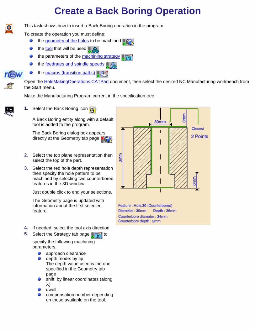
Create a Back Boring OperationThis task shows how to insert a Back Boring operation in the program.
To create the operation you must define:the geometry of the holes to be machined
the tool that will be used
the parameters of the machining strategy
the feedrates and spindle speeds
the macros (transition paths) .
Open the HoleMakingOperations.CATPart document, then select the desired NC Manufacturing workbench fromthe Start menu.
Make the Manufacturing Program current in the specification tree.
1. Select the Back Boring icon .
A Back Boring entity along with a defaulttool is added to the program.
The Back Boring dialog box appearsdirectly at the Geometry tab page .
2. Select the top plane representation thenselect the top of the part.
3. Select the red hole depth representationthen specify the hole pattern to bemachined by selecting two counterboredfeatures in the 3D window.
Just double click to end your selections.
The Geometry page is updated withinformation about the first selectedfeature.
4. If needed, select the tool axis direction.5. Select the Strategy tab page to
specify the following machiningparameters.
approach clearancedepth mode: by tipThe depth value used is the onespecified in the Geometry tabpageshift: by linear coordinates (alongX)dwellcompensation number dependingon those available on the tool.

A tool is proposed by default when you want to create a machining operation.
If the proposed tool is not suitable, just select the Tool tab page to specify the tool you want to use.
This is described in Edit the Tool of an Operation.6. Select the Feeds and Speeds tab page to specify the feedrates and spindle speeds for the operation.
Note that in the tool path represented in the strategy page, tool motion is as follows:Shift motion at rapid feedrate from 1 to 2Motion at rapid feedrate from 2 to 3Shift motion at rapid feedrate from 3 to 4Motion at machining feedrate from 4 to 5Dwell for specified durationMotion at machining feedrate from 5 to 6Shift motion at approach feedrate from 6 to 7Retract at retract feedrate from 7 to 8Shift motion at approach feedrate from 8 to 9.
7. If you want to specify approach and retract motion for the operation, select the Macros tab page tospecify the desired transition paths.
The general procedure for this is described in Define Macros of an Axial Machining Operation.
Before accepting the operation, you should check its validity by replaying the tool path.
8. Click OK to create the operation.

Example of output
If your PP table is customized with the following statement for Back Boring operations:CYCLE/BORE, %MFG_TOTAL_DEPTH, %MFG_FEED_MACH_VALUE, &MFG_FEED_UNIT, %MFG_CLEAR_TIP, ORIENT, %MFG_XOFF, DWELL, %MFG_DWELL_REVOL
A typical NC data output is as follows:CYCLE/BORE, 25.000000, 500.000000, MMPM, 5.000000, ORIENT, 1.000000, DWELL, 3
However, if the Syntax Used option is set to No for NC Output generation, then GOTO points will begenerated instead of this PP word syntax.

Create a Tapping OperationThis task shows how to insert a Tapping operation in the program.
To create the operation you must define:the geometry of the holes to be machined
the tool that will be used
the parameters of the machining strategy
the feedrates and spindle speeds
the macros (transition paths) .
Open the HoleMakingOperations.CATPart document, then select the desired NC Manufacturing workbench fromthe Start menu.
Make the Manufacturing Program current in the specification tree.
1. Select the Tapping icon .
A Tapping entity along with a default toolis added to the program.
The Tapping dialog box appears directlyat the Geometry tab page .
This tab page includes an iconrepresenting a simple hole. There areseveral hot spots in the icon.
2. Select the red hole depth representationthen select a threaded hole feature in the3D window.Just double click to end your selection.
The sensitive icon is updated with thefollowing information:
hole depth, thread depth, anddiameterhole extension type: blind.
3. If needed, select tool axis direction.4. Select the Strategy tab page to
specify the following machiningparameters.
approach clearancedepth mode: by shoulderThe depth value used is the onespecified in the Geometry tabpage.compensation number dependingon those available on the tool.
The other parameters are optional in thiscase.

A tool is proposed by default when you want to create a machining operation.
If the proposed tool is not suitable, just select the Tool tab page to specify the tool you want to use.
This is described in Edit the Tool of an Operation.5. Select the Feeds and Speeds tab page to specify the feedrates and spindle speeds for the operation.
Note that in the tool path represented in the strategy page, tool motion is as follows:Motion at machining feedrate from 1 to 2Reverse spindle rotationRetract at machining feedrate from 2 to 3Reverse spindle rotation.
If you want to specify approach and retract motion for the operation, select the Macros tab page tospecify the desired transition paths.
The general procedure for this is described in Define Macros of an Axial Machining Operation.
Before accepting the operation, you should check its validity by replaying the tool path.
6. Click OK to create the operation.Example of output
If your PP table is customized with the following statement for Tapping operations:CYCLE/TAP, %MFG_TOTAL_DEPTH, %MFG_FEED_MACH_VALUE, &MFG_FEED_UNIT,%MFG_CLEAR_TIP
A typical NC data output is as follows:CYCLE/TAP, 38.500000, 500.000000, MMPM, 2.500000
However, if the Syntax Used option is set to No for NC Output generation, then GOTO points will begenerated instead of this PP word syntax.


Create a Reverse Threading OperationThis task shows how to insert a Reverse Threading operation in the program.
To create the operation you must define:the geometry of the holes to be machined
the tool that will be used
the parameters of the machining strategy
the feedrates and spindle speeds
the macros (transition paths) .
Open the HoleMakingOperations.CATPart document, then select the desired NC Manufacturing workbench fromthe Start menu.
Make the Manufacturing Program current in the specification tree.
1. Select the Reverse Threading icon .
A Reverse Threading entity along with adefault tool is added to the program.
The Reverse Threading dialog boxappears directly at the Geometry tabpage .
2. Select the red hole depth representationthen select a threaded hole feature inthe 3D window.Just double click to end your selection.
The sensitive icon is updated with thefollowing information:
hole depth, thread depth, anddiameterhole extension type: blind.
3. If needed, select the tool axis direction.4. Select the Strategy tab page to
specify the following machiningparameters.
approach clearancedepth mode: by shoulderThe depth value used is the onespecified in the Geometry tabpage.compensation number dependingon those available on the tool.
The other parameters are optional in thiscase.

A tool is proposed by default when you want to create a machining operation.
If the proposed tool is not suitable, just select the Tool tab page to specify the tool you want to use.
This is described in Edit the Tool of an Operation.5. Select the Feeds and Speeds tab page to specify the feedrates and spindle speeds for the operation.
Note that in the tool path represented in the strategy page, tool motion is at:Motion at machining feedrate from 1 to 2Spindle off then reverse spindle rotationRetract at machining feedrate from 2 to 3.
6. If you want to specify approach and retract motion for the operation, select the Macros tab page tospecify the desired transition paths.
The general procedure for this is described in Define Macros of an Axial Machining Operation.
Before accepting the operation, you should check its validity by replaying the tool path.
7. Click OK to create the operation.Example of output
If your PP table is customized with the following statement for Reverse Threading operations:CYCLE/TAP, %MFG_TOTAL_DEPTH, %MFG_FEED_MACH_VALUE, &MFG_FEED_UNIT,%MFG_CLEAR_TIP
A typical NC data output is as follows:CYCLE/TAP, 38.500000, 500.000000, MMPM, 2.500000
However, if the Syntax Used option is set to No for NC Output generation, then GOTO points will begenerated instead of this PP word syntax.


Create a Thread without Tap Head OperationThis task shows how to insert a Thread without Tap Head operation in the program.
To create the operation you must define:the geometry of the holes to be machined
the tool that will be used
the parameters of the machining strategy
the feedrates and spindle speeds
the macros (transition paths) .
Open the HoleMakingOperations.CATPart document, then select the desired NC Manufacturing workbench fromthe Start menu.
Make the Manufacturing Program current in the specification tree.
1. Select the Thread without Tap Head icon.
A Thread without Tap Head entity alongwith a default tool is added to theprogram.
The Thread without Tap Head dialog boxappears directly at the Geometry tabpage .
2. Select the red hole depth representationthen select a threaded hole feature in the3D window.Just double click to end your selection.
The sensitive icon is updated with thefollowing information:
hole depth, thread depth, anddiameterhole extension type: blind.
3. If needed, select the tool axis direction.4. Select the Strategy tab page and
specify the following machiningparameters.
approach clearancedepth mode: by tipThe depth value used is the onespecified in the Geometry tabpage.compensation number dependingon those available on the tool.
The other parameters are optional in thiscase.

A tool is proposed by default when you want to create a machining operation.
If the proposed tool is not suitable, just select the Tool tab page to specify the tool you want to use.
This is described in Edit the Tool of an Operation.5. Select the Feeds and Speeds tab page to specify the feedrates and spindle speeds for the operation.
Note that in the toolpath represented in the strategy page, tool motion is as follows:Motion at machining feedrate from 1 to 2Spindle stopRetract at retract feedrate from 2 to 3.
6. If you want to specify approach and retract motion for the operation, select the Macros tab page tospecify the desired transition paths.
The general procedure for this is described in Define Macros of an Axial Machining Operation.
Before accepting the operation, you should check its validity by replaying the tool path.
7. Click OK to create the operation.Example of output
If your PP table is customized with the following statement for Thread without Tap Head operations:CYCLE/TAP, %MFG_TOTAL_DEPTH, %MFG_FEED_MACH_VALUE, &MFG_FEED_UNIT,%MFG_CLEAR_TIP
A typical NC data output is as follows:CYCLE/TAP, 38.500000, 500.000000, MMPM, 2.500000
However, if the Syntax Used option is set to No for NC Output generation, then GOTO points will begenerated instead of this PP word syntax.


Create a Countersinking OperationThis task shows how to insert a Countersinking operation in the program.
To create the operation you must define:the geometry of the holes to be machined
the tool that will be used
the parameters of the machining strategy
the feedrates and spindle speeds
the macros (transition paths) .
Open the HoleMakingOperations.CATPart document, then select the desired NC Manufacturing workbench fromthe Start menu.
Make the Manufacturing Program current in the specification tree.
1. Select the Countersinking icon .
A Countersinking entity along with adefault tool is added to the program.
The Countersinking dialog box appearsdirectly at the Geometry tab page .
2. Select the red hole depth representationthen select hole geometry in the 3Dwindow.Just double click to end your selections.
3. If needed, select the tool axis direction.4. Select the Strategy tab page to
specify the following machiningparameters.
Approach clearanceDepth mode: by distanceThe depth value used is the onespecified in the Geometry tabpage.DwellCompensation number dependingon those available on the tool.
The other parameters are optional in thiscase.

A tool is proposed by default when you want to create a machining operation.
If the proposed tool is not suitable, just select the Tool tab page to specify the tool you want to use.
This is described in Edit the Tool of an Operation.5. Select the Feeds and Speeds tab page to specify the feedrates and spindle speeds for the operation.
Note that in the toolpath represented in the strategy page, tool motion is at:Motion at machining feedrate from 1 to 2Dwell for specified durationIncrement at finishing feedrate from 2 to 3Retract at retract feedrate from 3 to 4.
6. If you want to specify approach and retract motion for the operation, select the Macros tab page tospecify the desired transition paths.
The general procedure for this is described in Define Macros of an Axial Machining Operation.
Before accepting the operation, you should check its validity by replaying the tool path.
7. Click OK to create the operation.Example of output
If your PP table is customized with the following statement for Countersinking operations:
CYCLE/CSINK, %MFG_TOTAL_DEPTH, %MFG_FEED_MACH_VALUE, &MFG_FEED_UNIT, %MFG_CLEAR_TIP, DWELL, %MFG_DWELL_REVOL
A typical NC data output is as follows:CYCLE/CSINK, 25.000000, 500.000000, MMPM, 5.000000, DWELL, 3
However, if the Syntax Used option is set to No for NC Output generation, then GOTO points will begenerated instead of this PP word syntax.


Create a Chamfering Two Sides OperationThis task shows how to insert a Chamfering Two Sides operation in the program.
To create the operation you must define:the geometry of the holes to be machined
the tool that will be used
the parameters of the machining strategy
the feedrates and spindle speeds
the macros (transition paths) .
Open the HoleMakingOperations.CATPart document, then select the desired NC Manufacturing workbench fromthe Start menu.
Make the Manufacturing Program current in the specification tree.
1. Select the Chamfering Two Sides icon.
A Chamfering Two Sides entity alongwith a default tool is added to theprogram.
The Chamfering Two Sides dialog boxappears directly at the Geometry tabpage .
2. Select the red hole depth representationthen select the hole geometry in the 3Dwindow.Just double click to end your selections.
3. If needed, select the tool axis direction.4. Select the Strategy tab page to
specify the following machiningparameters:
approach clearances 1 and 2depth mode: by tipbreakthrough distancedwell in secondsfirst compensation numberdepending on those available onthe tool for top chamferingsecond compensation numberdepending on those available onthe tool for bottom chamfering.
Please note that the depth value andchamfer diameter are retrieved from yourgeometry selections.

A tool is proposed by default when you want to create a machining operation.
If the proposed tool is not suitable, just select the Tool tab page to specify the tool you want to use.
This is described in Edit the Tool of an Operation.5. Select the Feeds and Speeds tab page to specify the feedrates and spindle speeds for the operation.
Note that in the tool path represented in the strategy page, tool motion is as follows:Motion at machining feedrate from 1 to 2Dwell for specified durationPossibly, activation of second tool compensation number (output point change)Motion at approach feedrate from 2 to 3Motion at machining feedrate from 3 to 4Dwell for specified durationPossibly, activation of first tool compensation number (output point change)Retract at retract feedrate from 4 to 5.
6. If you want to specify approach and retract motion for the operation, select the Macros tab page tospecify the desired transition paths.
The general procedure for this is described in Define Macros of an Axial Machining Operation.
Before accepting the operation, you should check its validity by replaying the tool path.
7. Click OK to create the operation.

Example of output
If your PP table is customized with the following statement for Chamfering Two Sides operations:CYCLE/BORE, %MFG_TOTAL_DEPTH, %MFG_FEED_MACH_VALUE, &MFG_FEED_UNIT, %MFG_CLEAR_TIP, DWELL, %MFG_DWELL_REVOL
A typical NC data output is as follows:CYCLE/BORE, 25.000000, 500.000000, MMPM, 5.000000, DWELL, 3
However, if the Syntax Used option is set to No for NC Output generation, then GOTO points will begenerated instead of this PP word syntax.

Create a T-Slotting OperationThis task shows how to insert a T-Slotting operation in the program.
To create the operation you must define:the geometry of the holes to be machined
the tool that will be used
the parameters of the machining strategy
the feedrates and spindle speeds
the macros (transition paths) .
Open the HoleMakingOperations.CATPart document, then select the desired NC Manufacturing workbench from theStart menu.
Make the Manufacturing Program current in the specification tree.
1. Select the T-Slotting icon .
A T-Slotting entity along with a default toolis added to the program.
The T-Slotting dialog box appears directlyat the Geometry tab page .
2. Select the red hole depth representationthen select hole geometry in the 3Dwindow.Just double click to end your selections.
3. If needed, select the tool axis direction.4. Select the Strategy tab page to
specify the following machiningparameters.
Approach clearanceDepth mode: by tipThe depth value used is the onespecified in the Geometry tab page.DwellCompensation number dependingon those available on the tool.
The other parameters are optional in thiscase.

A tool is proposed by default when you want to create a machining operation.
If the proposed tool is not suitable, just select the Tool tab page to specify the tool you want to use.
This is described in Edit the Tool of an Operation.5. Select the Feeds and Speeds tab page to specify the feedrates and spindle speeds for the operation.
Note that in the toolpath represented in the strategy page, tool motion is at:Motion at approach feedrate from 1 to 2Motion at machining feedrate from 2 to 3Retract at retract feedrate from 3 to 4.
6. If you want to specify approach and retract motion for the operation, select the Macros tab page to specifythe desired transition paths.
The general procedure for this is described in Define Macros of an Axial Machining Operation.
Before accepting the operation, you should check its validity by replaying the tool path.
7. Click OK to create the operation.Example of output
If your PP table is customized with the following statement for T-Slotting operations:CYCLE/TAP, %MFG_TOTAL_DEPTH, %MFG_FEED_MACH_VALUE, &MFG_FEED_UNIT, %MFG_CLEAR_TIP
A typical NC data output is as follows:CYCLE/TAP, 38.500000, 500.000000, MMPM, 2.500000
However, if the Syntax Used option is set to No for NC Output generation, then GOTO points will be generatedinstead of this PP word syntax.

Create a Circular Milling OperationThis task shows how to insert a Circular Milling operation in the program.
To create the operation you must define:the geometry of the holes to be machined
the tool that will be used
the parameters of the machining strategy
the feedrates and spindle speeds
the macros (transition paths) .
Open the HoleMakingOperations.CATPart document, then select the desired NC Manufacturing workbench from theStart menu.
Make the Manufacturing Program current in the specification tree.
1. Select the Circular Milling icon .
A Circular Milling entity along with adefault tool is added to the program.
The Circular Milling dialog box appearsdirectly at the Geometry tab page .
2. Enter Offset values for the Bottom andContour.
3. Select the red hole depth representationthen select hole geometry in the 3Dwindow.Just double click to end your selections.
4. If needed, select the tool axis direction.5. Select the Strategy tab page to
specify the following machiningparameters.
Approach clearanceNumber and distance betweenpathsAxial mode:Maximum depth of cut or Number of levelsSequencing modeMachining toleranceDirection of cutPercentage overlapAutomatic draft angleCompensation number dependingon those available on the tool.

You can choose between the standard tipoutput and a cutter profile output bymeans of the Output style option. If a cutter profile style is selected, both thetip and cutter profile will be visualizedduring tool path replay. The cutter profile output allows easier toolcompensation to be done on the shopfloor.
A tool is proposed by default when you want to create a machining operation.
If the proposed tool is not suitable, just select the Tool tab page to specify the tool you want to use.
This is described in Edit the Tool of an Operation.6. Select the Feeds and Speeds tab page to specify the feedrates and spindle speeds for the operation.
Note that in the toolpath represented in the strategy page, tool motion is at:Motion at machining feedrate from 1 to 2Motion at feedrates defined on macros from 2 to 3, 3 to 4, 4 to 2', 2' to 3' and 3' to 4'Retract at retract feedrate from 4' to 5.
7. Select the Macros tab page to specify the operation's transition paths (approach and retract motion, forexample).
The general procedure for this is described in Define Macros of an Operation.
Before accepting the operation, you should check its validity by replaying the tool path.
8. Click OK to create the operation.

Example of output
If your PP table is customized with the following statement for Circular Milling operations:CYCLE/CIRCULARMILLING, %MFG_TOTAL_DEPTH, %MFG_FEED_MACH_VALUE, &MFG_FEED_UNIT, %MFG_CLEAR_TIP
A typical NC data output is as follows:CYCLE/CIRCULARMILLING, 38.500000, 500.000000, MMPM, 2.500000
However, if the Syntax Used option is set to No for NC Output generation, then GOTO points will be generatedinstead of this PP word syntax.

Auxiliary OperationsThis section shows you how to insert auxiliary operations in the manufacturing program.
Insert Tool Change: Select the Tool Change icon then select the tool type to be referenced in the tool change.
Insert Machine Rotation: Select the Machine Rotation icon then specify the tool rotation characteristics.
Insert Machining Axis System or Origin: Select the Machining Axis or Origin icon then specify the characteristicsof the machining axis system or origin.
Insert PP Instruction: Select the PP Instruction icon then enter the syntax of the PP instruction.

Insert a Tool ChangeThis task shows how to insert tool changes in the program.
You can either add tool changes locally or generate all necessary tool changes automatically in the program.1. To add a tool change locally:
In the specification tree, select theprogram entity after which you want to addthe tool change.
2. Select the Tool Change icon .
The Tool Change dialog box appears.
3. Select the Tool tab page in order tospecify the tool to be referenced by thetool change. You can do this by either:
creating a new tool selecting another tool that isalready used in the documentselecting another tool either in thedocument or in tool catalogs bymeans of a query.
This is the same procedure as describedin Select or Create a Tool.
4. Select the Syntax tab page .
Select the Init from PP Table checkbox to consult the tool change syntax defined in the PP table that isreferenced by the Part Operation.Otherwise, enter a PP Instruction for your tool change. This user-defined syntax has no link with the PPtable and its validity is not checked by the program.If the PP Instruction comprises a sequence of PP word syntaxes, you can choose the sequence to be usedby means of the Sequence Number spinner.
5. Click OK to create the tool change in the program.
You can click Replay to visualize the tool at the tool change point in the program.

1. To generate tool changes automatically:
Right click the Manufacturing Program entity in the specification tree and select Generate Tool Changes from thecontextual menu.
The program is updated with all necessary tool changes.2. To delete tool changes that were automatically generated :
Right click the Manufacturing Program entity in the specification tree and select Delete Generated Tool Changesfrom the contextual menu.
All tool changes that were automatically generated are removed from the program.

Insert a Machine RotationThis task shows how to insert a machine rotation in the program.
You can either add machine rotations locally or generate all necessary machine rotations automatically in theprogram.Either the program or a program entity must be current in the specification tree.
1. To add a machine rotation locally:
In the specification tree, select theprogram entity after which you want toadd the machine rotation, then select theMachine Rotation icon .
The Machine Rotation dialog boxappears.
2. Select the Properties tab page tospecify the characteristics of the Machinerotation.
3. Select the rotary direction:ClockwiseCounter-clockwise.
4. Enter the value of the angle of rotationabout the rotary axis.
Note that this rotary axis (A, B or C) isdefined on the machine referenced by thePart Operation.The rotary type is set to Absolute in this version.
5. Select the Syntax tab page .
Select the Init from PP Table checkbox to consult the machine rotation syntax defined in the PP table thatis referenced by the Part Operation.Otherwise, enter a PP Instruction for your machine rotation. This user-defined syntax has no link with thePP table and its validity is not checked by the program.
6. Click OK to accept creation of the machine rotation in the program.1. To generate machine rotations automatically:
Right click the Manufacturing Program entity in the specification tree and select Generate Machine Rotations fromthe contextual menu.
The program is updated with all necessary machine rotations.2. To delete machine rotations that were automatically generated:
Right click the Manufacturing Program entity in the specification tree and select Delete Generated MachineRotations from the contextual menu.
All machine rotations that were automatically generated are removed from the program.

Insert a Machining Axis or OriginThis task shows how to insert a machining axis or origin auxiliary operation in the program.
A feature representation of the corresponding axis system will be created in the 3D view.
Output coordinates are computed in the current machining axis system as shown in the example below.
Tool path computed in machining axis system AXS1 with origin (0,0,0):$$*CATIA0
$$*AXS1
$$ 1.00000 0.00000 0.00000 0.00000
$$ 0.00000 1.00000 0.00000 0.00000
$$ 0.00000 0.00000 1.00000 0.00000
GOTO/ -40.00000, -30.00000, 20.00000
GOTO/ -40.00000, 30.00000, 20.00000
Same tool path computed in machining axis system AXS2 with origin (0,0,20):$$*CATIA0
$$*AXS2
$$ 1.00000 0.00000 0.00000 0.00000
$$ 0.00000 1.00000 0.00000 0.00000
$$ 0.00000 0.00000 1.00000 20.00000
GOTO/ -40.00000, -30.00000, 0.00000
GOTO/ -40.00000, 30.00000, 0.00000
Either the program or a program entity must be current in the specification tree.
1. Select the Machining Axis or Origin icon .
The Operation Definition dialog box is displayeddirectly at the Geometry tab page .
You can now select geometric elements to defineyour axis system.
2. Select the symbol representing the origin in thesensitive icon.
3. Select a point or a circle to define the origin of themachining axis.

4. Select one of the axes (Z, for example) in thesensitive icon to specify the orientation of that axis.
The following dialog box appears.
The Z axis is the privileged axis. You should defineit first, then specify the X axis. The XY plane isalways perpendicular to the Z axis.
5. Select the desired method to specify the orientation using the combo:Manual: by means of X, Y, Z componentsSelectionMain axis: from a pre-defined list.
Just click OK to accept the specified orientation.6. Repeat this procedure to specify the orientation of another axis (X, for example).
The specified origin and X and Z axes are sufficient to define the machining axis system. You can also define a machining axis by selecting one of the triangular areas in the sensitive icon.
You can then select an existing axis system and position it by selecting a point in the 3D view.7. You can click the Origin checkbox if you want to specify an origin.
For certain machine types it may be useful to specify an origin number and group.
This will result in the following type of output syntax:$$*CATIA0
$$Origin.1
$$ 1.00000 0.00000 0.00000 0.00000
$$ 0.00000 1.00000 0.00000 0.00000
$$ 0.00000 0.00000 1.00000 0.00000
ORIGIN/ 0.00000,0.00000,0.00000, 1, 1
This output is for an origin with coordinates (0,0,0) and whose origin number and group are both equal to 1. 8. You can enter a name for the machining axis or origin to be created. This name will be visualized beside the
representation of the axis system in the 3D view. 9. Select the Syntax tab page .
Select the Init from PP Table checkbox to consult the Machining Axis or Origin syntax defined in the PPtable that is referenced by the Part Operation.Otherwise, enter a PP Instruction for your machining axis or origin. This user-defined syntax has nolink with the PP table and its validity is not checked by the program.
10. Click OK to create the machining axis or origin auxiliary operation in the program.
A feature representation of the corresponding axis system is created in the 3D view.

Insert a PP InstructionThis task shows how to insert a PP instruction in the program.
Either the program or a program entity must be current in the specification tree.
1. In the specification tree, select theprogram entity after which you wantto add the PP instruction.
2. Select the PP Instruction icon .
The Post-Processor Instructiondialog box appears.
3. Enter the syntax of a PP instruction.
Please note that the program does not check the validity of your syntax.
4. Click OK to create the PP instruction in the program.

Part Operation and Manufacturing ProgramThis section deals with creating and managing the following major entities of the CATIA manufacturing environment.
Create and Edit a Part Operation: Select the Part Operation icon then specify the entities to be referenced by thepart operation: machine tool, machining axis system, tool change point, part set up, and so on. Create and Edit a Manufacturing Program: Select the Manufacturing Program icon to add a program to thecurrent part operation then insert all necessary program entities: machining operations, tool changes, PPinstructions, and so on.

Part OperationThis task shows you how to create a part operation in the manufacturing process.
When you open an NC Manufacturing workbench on a CATPart or CATProduct document, the manufacturingdocument is initialized with a part operation.
1. Select the Part Operation icon .
A new part operation is initialized in the manufacturingprocess and a Part Operation entity is added to the tree.
To access the parameters of the part operation, doubleclick the Part Operation entity in the tree or use thecontextual menu.
The Part Operation dialog box appears.
2. If needed, enter a new part operation name and assigncomments to the part operation.
3.Click the Machine icon to assign a machine tool to the part operation.
The Machine Editor dialog box appears.

4.
Select the desired type of machine tool by clicking the corresponding icon:3-axis machine3-axis machine with rotary table5-axis machine.
The default characteristics of the selected machine type are displayed and the following parameters can beedited to correspond to your actual machine tool.
Machine name and associated commentsNumerical control parameters such as PP words tableSpindle parametersTool change parameters such as Tools catalogRotary table parameters for 3-axis machine with rotary table.
Just click OK to accept the machine parameters and return to the Part Operation dialog box.5. Click the Machining Axis icon to assign a reference machining axis system to the part operation.
The Machining Axis dialog box appears.
This is similar to the procedure described in Insert a Machining Axis Change.
Output coordinates will be described in the specified axis system except when local machining axis systems areinserted in the program.
6. Click the Product icon to associate an existing product (CATProduct) or part (CATPart) to the part operation.
This procedure is described in Set Up and Part Positioning.

7. Select the Geometry tab to associate the following geometry to the part operation:Design part
Just click the Design Part icon then select the desired geometry.This is useful if you want to do material removal simulations later. Stock
Just click the Stock icon then select the desired geometry.This is useful if you want to do material removal simulations later. Safety plane
Just click the Safety Plane icon then select the desired plane that will be used as a global safety planefor the part operation.
8. Select the Position tab to specify the following entities on the part operation:tool change point part setup on the machine.
9. Click OK to create the part operation.
The tree is updated with the new entity.

Manufacturing ProgramThis task shows you how you can edit a manufacturing program.
A number of capabilities are available for managing manufacturing programs:CreateInsert entitiesReorder using Copy / Paste or Drag / DropDelete.
When you open an NC Manufacturing workbench on a CATPart document, the manufacturing document is initializedwith a manufacturing program.
When you select the Manufacturing Program icon , a new program is initialized in the part operation and a newManufacturing Program entity is added to the tree.Open the HoleMakingOperations.CATPart document, then select NC Manufacturing > Prismatic Machining from theStart menu.
Make the Manufacturing Program current in the specification tree.
1. Create a drilling operation on a pattern of two holes.
2. Create a spot drilling operation on the same holes.
3. Create another drilling operation on another pattern offour holes.
The three operations are assigned the same defaulttool.
4. Edit the spot drilling operation to assign a spot drill tool.
Each operation now has an associated tool change.
5. Right click the second Drilling operation and select theCut command.

6. Right click the first Drilling operation and select thePaste command.
The program is now reordered and the number of toolchanges reduced.
The same result could have been obtained by using the drag and drop capability.

Managing Manufacturing EntitiesThis section deals with creating and managing the specific entities of the CATIA manufacturing environment (other thanmachining operations and auxiliary commands).
Select or Create a Tool: Double click the machining operation in the program and select the Tool tab page to editthe tool characteristics or search for a new tool.Edit a Tool Referenced in the Program: Double click a tool referenced in the program or resource list and edit thetool characteristics in the Tool Definition dialog box.Specify Tool Compensation Information: Double click a tool referenced in the program or resource list and specifythe tool compensation information in the Compensation tab page of the Tool Definition dialog box .Create and Use Machining Patterns: Select Insert > Machining Feature > Machining Pattern then select a patternof holes to be machined.Feature Based Programming: Select a feature using the Manufacturing view and create operations based on thisfeature.Define Macros on a Milling Operation: Select the Macros tab page when creating or editing a milling operation,then specify the transition paths of the macros to be used in the operation.Define Macros on an Axial Machining Operation: Select the Macros tab page when creating or editing an axialmachining operation, then specify the transition paths of the macros to be used in the operation.Manage the Status of Manufacturing Entities: Use the status lights to know whether or not your operation iscorrectly defined.

Select or Create a ToolThis task shows you how to edit the tool of an operation. You can either:
create a new toolselect another tool that is already used in the documentselect another tool by means of a query.
1. Double click the operation in the program, then select the Tool tab page.
2. To create a new tool:
If you want to change tool type, select the iconcorresponding to the desired tool type.
In this case the corresponding tool representationappears in the 2D viewer.
Double click the geometric parameter thatyou want to modify in the 2D viewer, thenenter the desired value in the EditParameters dialog box that appears.
Modify other parameters in the same way.The tool representation is updated to takethe new values into account.
Click More to expand the dialog box toaccess all the tool's parameters.Modify the values as desired.
Use the spinner to increment the Toolnumber.
Enter a name for the new tool.
3. To select a tool that is already used in the document:Select the button opposite Name.
Select the desired tool from the list of tools already used in your document.
If necessary, you can edit the parameters of this tool as described above. 4. To select another tool by means of a query:
Click the Select a tool by query iconopposite Name.The Search Tool dialog box appears.
You can choose to search in the currentdocument or a tool catalog by means ofthe Look in combo.
If you want to change tool type, select theicon corresponding to the desired tooltype.

You can do a simple search by means of acharacter string on the tool name or avalue for the tool's nominal diameter. The tools meeting the simple searchcriteria are listed.
Select the desired tool from the list andclick OK. The tool representation is displayed in the2D viewer and can be edited as describedabove.
You can search a tool using finer constraints by selecting the Advanced tab page.
The example below shows the result of a search for a tool with body diameter between 10 and 15 mm in thecatalog ToolsSample02.
5. Click OK to confirm using this new tool in the operation.


Edit a Tool in the Program or Resource ListThis task shows you how to edit a tool that is already used in your document.
1. Right click the tool you want to edit either in the program or in the resource list to access the Definitioncontextual command.The Tool Definition dialog box is displayed allowingyou to edit the tool's geometric, technological andcompensation characteristics.
2. If needed, enter a new name for the tool.
3. If needed, use the spinner to increment the Toolnumber.
4. Click More to expand the dialog box to access theGeometry, Technology and Compensation tabpages.
5. You can specify the tool geometry in two ways:double click a parameter in the large toolicon and enter the desired value in the EditParameter dialog box that appearsor enter the desired values in the Geometrytab page.
The icon representation of the tool is updated withthese values.

6. Click the Technology tab and enter the desiredvalues for the tool's technological parameters.
7. If tool compensation is required, click theCompensation tab.
You can either edit an existing compensation siteor add another site, if other sites are proposed forthe type of tool being created.
8. Right click the desired line to either edit or add tool compensation data.
The Compensation Definition dialog box appears.9. Enter the desired values for the tool's compensation sites.
See Specify Tool Compensation for more information.10. Click OK to accept the modifications made to the tool.

Specify Tool CompensationThis task shows you how to specify tool compensation information.
1. Select the Compensation tab page of the Tool Definition dialog box.
2. Right click the desired compensation site to either editor add tool compensation data.
The Compensation Definition dialog box is displayedallowing you to specify the tool's compensationcharacteristics.
3. You can associate the following information to eachcompensation site on a tool:
corrector numberlength register numberradius register number (if radius compensation isallowed on the machine referenced by the partoperation)diameter in order to specify the compensationsite location (if allowed for the tool). Site P2 of adrill, for example.
The following tool types have only one compensation site. This is the site P1 located at the extremity of the tool.
End mill Face mill Boring tool
Tap Reamer

The following tool types have more than one compensation site. Some sites are defined by means of a diametervalue.
Drill Multi-diameter drill Center drill
Spot drill Boring and chamfering tool T-slotter
Conical mill Countersink Two sides chamfering tool4. Click OK to update the tool with the desired compensation information.
It is possible to define tool compensation site numbers for all machining operation types, if tool compensationnumbers are already defined on the tool used by the machining operation.
In general, the tool compensation site number used by the operation can be specified.For operations such as Boring and Chamfering, Chamfering Two Sides or Contouring (when a T-slotter is used),two tool compensation site numbers can be used during machining.


Machining PatternsThis task shows you how to:
create a specific machining feature called machining patternuse this pattern of holes by referencing it directly in a drilling operation.
Create a machining pattern
1. Select the Manufacturing Feature View icon todisplay the Manufacturing View.
2. Select the Insert > Machining Features > MachiningPattern command.
A Machining Pattern entity is added to theManufacturing View.
3. Right click the Machining Pattern entity and select theDefinition contextual menu command.
The Machining Pattern dialog box is displayed.4. Click the No Points sensitive text in the dialog box, then
select the points to be included in the machining pattern.
The icon is updated with this information.
5. Click OK to create the machining pattern.
Use a machining pattern in a machining operation
1. Select the Drilling icon .
The Drilling dialog box appears directly at the Geometry tab page.
This tab page includes a sensitive icon to help you specify the geometry of the hole or hole pattern to bemachined.
2. Select the red hole depth representation then select the machining pattern from the displayed list.
The pattern is highlighted in the model.3. Click OK to create the drilling operation: the holes of the machining pattern will be drilled by this operation.


FeaturesThis task shows you how to use features displayed in the Manufacturing View for NC programming.
1. Select the Manufacturing Feature View icon to display theManufacturing View.
2. Select a feature in the View (Hole5, for example).
The operations to be created will be attached to this feature.
3. To attach a spot drilling operation to the feature, select the SpotDrilling icon .
The Spot Drilling dialog box appears. Select the Geometry tabpage.
This tab page includes a sensitive icon to help you specify thegeometry of the hole or hole pattern to be machined.
4. Click the 1 Point sensitive text in the dialog box, then select the points to be included along with Hole5 in themachining pattern (Hole6, Hole7, Hole8, for example).
The icon is updated with this information.

5. Click OK to create the Spot Drilling operation, which is createdwith Machining Pattern.1 comprising 4 holes.
The Manufacturing View is updated.
6. Select the Drilling icon .
In Geometry tab page of the Drilling dialog box, click the No Points sensitive text in the dialog box, then selectMachining Pattern.1 from the displayed list.
7. Click OK to create the Drilling operation, which is created withMachining Pattern.2, which references Machining Pattern.1 for theposition of the four holes in the pattern.
The Manufacturing View is updated.

8. Replay the two operations in the program to check that they both use the selected machining pattern based on theinitial feature selection.You can use the contextual menu to sort the manufacturing viewby Features, Patterns, Activities or Tools.
If you edit the Machining Pattern.1 (to include more points, for example) both the Spot Drilling and Drilling operationswill be updated.

Define Macros on a Milling OperationThis task shows you how to define macros on a milling operation. In this example you will create circular approach,circular retract and linking macros on a Profile Contouring operation. You must have created the previously described Profile Contouring operation.
1. Double click the Profile Contouring operation.
2.Select the Macros tab page .
3. Click the Approach macro checkbox, then select thecircular approach icon.
A sensitive icon representing the elementary paths ofthe macro appears.
4. Set the values of the approach macros paths so as tohave a 10mm vertical path followed by a 15mm radiuscircular path.
Just double click the displayed values in order to editthem.
A dialog box appears to allow you to specify the exactcharacteristics of the circular path.
You can click Replay to check the circular approach.
5. Click the Retract macro check box and create a circular retract macro in the same way. 6. Click the Linking macro checkbox.
Linking Retract is automatically displayed in the comboallowing you to specify the retract path of the linkingmacro.
Select the linear retract path icon.

7. Double click the displayed value, then assign an 20mmvalue to the retract path.
8. Select Linking Approach in the combo. Select the linear approach path icon and assign a 20mm value to theapproach path.
9. Click the Cornerized Clearance with Radius checkbox,then enter a corner radius value of 3mm.

10. Click Replay to validate the tool path.
11. In the Replay dialog box select the By colors mode in order to visualize feedrate changes. The tool path isdisplayed with the following colors:
Yellow: approach feedrateGreen: machining feedrateBlue retract feedrateRed: Rapid feedrate.
12. Click OK to accept the modifications made to the operation.
The operation is updated with the specified macros.

Define Macros on an Axial Machining OperationThis task shows you how to define macros on an axial machining operation. In this example you will add approach,retract and linking macros to an existing Drilling operation. You must have created the previously described Drilling operation.
1. Double click the Drilling operation.
2.Select the Macros tab page .
3. Click the Approach macro definition checkbox, then
select the Add Axial Motion icon .
A sensitive icon representing the elementary paths of themacro appears.
4. Double click the displayed value in order to edit it.
A dialog box appears to allow you to specify the desireddistance (30mm, for example).
5. Click the Retract macro definition checkbox and create a 30 mm axial retract motion in the same way. 6. Click the Linking macro definition checkbox and create 25mm axial approach and retract motions for the linking
macro.7. Click Replay to validate the tool path.
In the Replay dialog box select the By colors mode in order to visualize feedrate changes. The tool path isdisplayed with the following colors:
Yellow: approach feedrate

Green: machining feedrateBlue: retract feedrateRed: Rapid feedratePurple: plunge feedrateWhite: local feedrate.
Note that if a jump distance is defined on the operation, it will be used in preference to the linking macro.
Similarly if local entry/exit distances are defined on the operation, they will be used in preference to the linkingmacro.
8. Click OK to accept the modifications made to the operation.
The operation is updated with the specified macros.

Status ManagementThis task shows you how the status of manufacturing entities is managed.
1. Select the Pocketing icon .
The Pocketing Definition dialog box appears directlyat the Geometry tab page.
The status light on the tab is red indicatingthat you must specify the geometry to be machinedby the operation.
A symbol on the Pocketing entity in thespecification tree also indicates that the operationdefinition is incomplete.
2. Select the required pocket geometry. The status light switches to green on the tab .
The status lights on the Strategy , Feeds and Macros tab are all green indicating that defaultvalues are already set for operation creation. You can of course modify these values. Just select the corresponding tab to access these parameters.
The status lights on the Tool tab is orange. This indicates that, although a default tool is set for theoperation, you may want to modify or change that tool for a more suitable one.
3. When all the status lights are green you generallyhave sufficient conditions to create the operation.
Just click OK to create the operation.
Remember that you should always check theoperation's tool path by means of a replay.
The symbol on the Pocketing tree entity isremoved when the operation definition is complete.
The operation name in the specification tree isappended with the text Computed after a replay isdone on the operation.

Verification, Simulation and Program OutputThis section shows you how to use the various tools provided with the product such as tool path verification, materialremoval simulation, and production of NC output data.
Replay Tool Path: Select the Tool Path Replay icon then specify the display options for an animated tool pathdisplay of the manufacturing program of machining operation. Simulate Material Removal: Select the desired icon in the Tool Path Replay dialog box to run a material removalsimulation either in Photo or Video mode.
Generate APT Source Code in Batch Mode: Select the Generate NC Code in Batch Mode icon then select themanufacturing program to be processed and define the APT source processing options. Generate ISO NC Code in Batch Mode: Select the Generate NC Code in Batch Mode icon then select themanufacturing program to be processed and define the ISO NC code processing options. Generate APT Source Code in Interactive Mode: Select the Generate NC Code Interactively icon to generateAPT source code for the current manufacturing program. Generate NC Documentation: Select the Generate Documentation icon to produce shop floor documentation inHTML format. Import an APT Source into the Program: Select the APT Import contextual command to insert an existing APTsource into the current manufacturing program.

Replay a Tool PathThis task shows you how to replay the tool path of an operation.
You can also replay the tool path of a manufacturing program.1. Select the operation in the tree, then
select the Replay icon .
You can also right-click the operationin the tree and select Replay ToolPath from the contextual menu.
The Replay dialog box appears.
You can also access the Replay dialog box directly from the Operation Definition dialog box.
2. Choose one of the replay modes byselecting one of the drop down icons:
Point to Point
Continuous
Plane by Plane
Feedrate by Feedrate .
3. Choose one of the Tool Visualizationmodes by selecting one of the dropdown icons:
Tool displayed at last positiononly Tool axis displayed at eachposition Tool displayed at each position
.
4. Choose a Color mode by selecting oneof the drop down icons:
Tool path displayed in samecolor Tool path displayed in differentcolors for different feedrates
.
5. Click the button to position the tool at the operation start point, then to start the replay.
You can use the other Tool Animation buttons to move the tool along the tool path as follows:
to go to the operation end point
to run the replay in reverse mode
to request a pause in the replay.
6. Click OK to quit the replay mode.

If the operation has been deactivated by means of the Deactivate command, it cannot be replayed. If youwant to replay the operation, you must reactivate it using the Activate command.
Similarly, if the manufacturing program has been deactivated by means of the Deactivate command, it cannotbe replayed. If you want to replay the program, you must reactivate it using the Activate command.If a Profile Contouring operation was created with the cutter profile output option, both the cutter profile andtip trajectory will be displayed in the replay.
If a user-defined tool representation is related to the operation, that tool will be displayed in the replay.

Material Removal SimulationThis task shows you how to simulate the material removed by a machining operation. Two modes are available: Photoand Video.
In Photo mode, you can only simulate operations whose tool axis is the same as the Z-axis of the Part Operation'smachining axis system.
In Video mode, if the stock geometry is not correctly closed, a stock representing the envelope volume of the designpart is computed.
Select the operation in the tree, thenselect the Replay icon .
You can also right-click the operation inthe tree and select Replay Tool Pathfrom the contextual menu.
The Replay dialog box appears.
1. Material Removal - Photo mode
Select the Photo icon .
The result of the material removal isdisplayed in a window entitled Photo.
The following icons become available foranalyzing the result of the simulation:
for comparing the machinedpart with the design part. for customizing materialremoval settings.
2. Select the Analyze Photo icon .
The Errors dialog box appears that givesdetails of all errors found.
3. In the Filter Setting section, select thedesired fault types and specify theTolerance for the comparison.
The fault filter setting permits three typesof faults:
Gouge: areas where the tool hasremoved excess material from theworkpiece.Undercut: areas where the toolhas left behind material on theworkpiece.

Tool Clash: areas where the toolcollided with the workpiece duringa rapid move.
4. Click the Compare button.
The machined part is compared with the design part based on the specified Filter Setting.
Any point on the machined surface of the workpiece is considered to be part of a fault if the normal distance(normal deviation) to the design part surface is greater than the specified tolerance.
Results of the comparison are reflected on the workpiece, based on the extent of severity of the fault and thecustomized color settings.The list of detected faults are listed in the Faults combo box.
The faults are ordered in such a way that Tool Clash appears at the top of the list followed by Gouge andUndercut. The gouges and undercuts are in turn sorted on the basis of decreasing fault area.
On selecting a fault from the Faults combo box, the region corresponding to the fault is indicated by a "FaultIndicator" bounding box on the workpiece.
Other detailed information about the selected fault is displayed.If needed, you can update the program data and display by clicking on the Photo icon again.
At any time you can pick on the surfaceof the workpiece. A dialog box appearsgiving information about the pick point:
The operation used for removingmaterial.The normal deviation between theworkpiece and the design part.The X, Y, and Z coordinates of thepick point.The tool used for machining.
5. Click Close to quit the Analyze Photo mode and return to the Replay dialog box.

1. Material Removal - Video mode
Select the Video icon .
The Material removal video is displayedin a window entitled Video.
The Replay mode is set to Point to Point.
2. Use the Tool animation replay buttons torun the material simulation video:
runrun one blockstoprewindrun reverse.
3. If needed, click the Save Video icon to save the material simulation video.
The Save Machined Workpiece dialog box appears allowing you to save the result of the simulation video in a cgrtype file.
4. Click OK to quit the Replay dialog box.

Generate NC Code InteractivelyThis task shows you how to generate NC code from the program in interactive mode.
For best results, you should have verified the operations of your program by replay or simulation. There should be nooperations to be updated or in an undefined state.
The generated NC code is in APT format.1. Select the Manufacturing Program entity
in the tree, then select the Generate NCCode Interactively icon .
You can also use the right mouse key onthe Manufacturing Program entity toselect Generate NC code.
The Save NC File dialog box appears.
2. Select the folder where the file is to besaved and specify the name of the file.
3. Click Save to create the APT file.
The generated APT file can be browsed with any kind of editor.

Generate NC Code in Batch ModeThis task shows you how to generate the NC code from the program in batch mode.
The NC code is generated in APT format.Always save your program modifications before generating the NC code.
For best results, you should have verified the operations of your program by replay or simulation. There shouldbe no operations to be updated or in an undefined state.1. Select the Manufacturing Program entity in the tree,
then select the Generate NC Code in Batch Modeicon .
The NC Batch Output dialog box appears.
2. In the In/Out tab page:
Specify the manufacturing program to be processedby:
either selecting the Current document checkbox or using the Document button and Programcombo.
3. Select APT as the type of NC data output that youwant.
4. Specify the file where you want the NC data to bewritten using the Output file button.
5. If needed, you can choose to write the document after processing. Just select the Save document checkbox and specify where you want to save it using the Document button.You can attach the generated output file to the selected manufacturing program by selecting the Associatedocument checkbox. The output file can be accessed by means of the Display NC File contextual commandon the manufacturing program.
6. In the Options tab page:
Specify the options to be used in the processing.
Some of these options take machine characteristicsinto account (for example, Circular Interpolation).
Others determine how information is to bepresented on the output file (for example,information statements to be presented with thePPRINT syntax).
Is Syntax Used is set to Yes, then for axialmachining operations the PP word syntax specifiedin the PP word table will be output . Otherwise,GOTO statements will be generated.
7. Click Execute to request computation of the APTsource file.


Generate ISO NC Code in Batch ModeThis task shows you how to generate ISO NC code from the program in batch mode.
Always save your program modifications before generating NC code.
For best results, you should have verified the operations of your program by replay or simulation. There shouldbe no operations to be updated or in an undefined state.1. Select the Manufacturing Program entity in the tree,
then select the Generate NC Code in Batch Modeicon .
The Generate NC Output in Batch Mode dialog boxappears.
2. In the In/Out tab page:
Specify the manufacturing program to beprocessed by:
either selecting the Current document checkbox or using the Document button and Programcombo.
3. Select ISO as the type of NC data output that youwant.
4. Specify the file you want the NC data to be writtenusing the Output file button.
5. If needed, you can choose to write the document after processing. Just select the Save document checkbox and specify where you want to save the document.
You can attach the generated output file to the selected manufacturing program by selecting the Associatedocument checkbox. The output file can be accessed by means of the Display NC File contextual commandon the manufacturing program. The setting of certain options in the Options tab page may have an influence on the generated ISO NCcode.
6. In the ISO tab page:
Use the combo to select the desired PostProcessor parameters file.
7. Click Execute to request computation of the NCcode.
Sample Post Processor parameter files are delivered with the product in the folder\Startup\Manufacturing\PPParwhich provides NC output for various machine types.For information about how to acquire Post Processor parameters files that provide machine specificISO NC code output, please contact your IBM representative.

Generate NC DocumentationThis task shows how to generate NC documentation in HTML format.
You can use the following scripting languages, depending on the platform you are running on:BasicScript 2.2 SDK for UNIX (BasicScript is a registered trademark of Summit Software Company)VBScript, short for Visual Basic Scripting Edition, for Windows NT (Visual Basic is a registered trademark ofMicrosoft Corporation).
Users on NT machines must have Windows Scripting Host installed.
You should have previously customized a CATScript file that defines the layout of the document you want to generate. Samples are delivered with the product in \Startup\Manufacturing\Documentation.1. Select the NC Documentation icon .
The Process Documentation dialog box appears.
2. Select the CATScript file by clicking the button on the right of the Script field.
In this version, just leave Process as the Process name.3. Specify the folder and file where the documentation is to be generated by clicking the button on the right of the
Path field.4. Click Document Now to generate your documentation.
A simple example is shown below.


APT ImportThis task shows how to import an existing APT file into the program.
1. Right click the Manufacturing Programentity in the specification tree and selectAPT Import from the contextual menu.
The Read NC File dialog box appears.
2. Navigate to find the folder in which the desired APT file is stored.3. Select the APT file in the displayed list then click Open to insert it in the program.
You can right-click the APT Import entity in the specification tree to access a contextual menu that allows you to:replay the APT source fileedit the APT source file definition.

Advanced TasksThe tasks described in this section deal with specific NC Manufacturing processes.
Design ChangesSet Up and Part Positioning

Design ChangesThis task shows you how to manage your design changes.
1. Create a Profile Contouring operation and replay the tool path.
All the tabs of the Profile Contouring dialog box display a green status.
The Profile Contouring entity is displayed in the tree with no related symbol.2. Switch to the window showing the CATpart design and modify the part geometry.3. Switch to the Set Up Editor manufacturing window.
The Profile Contouring entity is now displayed in the tree with an Update symbol.4. Double click the Profile Contouring entity to edit the operation.
The Geometry tab has an orange status, indicating that the geometry has been modified.5. Select the Analyze contextual command in
the sensitive icon zone of the dialog box.
The Geometry Analyzer dialog box appearsshowing the status of the referencedgeometry.
6. Click the Smart icon to highlight the geometrythat was used in the operation before the partwas modified.
Geometry highlighted in this way helps you toanalyze the design change.
7. Click OK to return to the Profile Contouringdialog box.
8. Replay the tool path to make sure that the machining is consistent with the design change.
You should check that there is no longer an Update symbol beside the Profile Contouring entity in the graph.

Set Up and Part PositioningThis task shows you how to manage part set up.
You must create a CATProduct entity for each part set up you want to represent.
1. Enter an NC Manufacturing workbench anddouble click the Part Operation.1 entity inthe tree.
The Part Operation dialog box appears.
2. Click the Product icon to associate a productto the part operation.
3. Select a CATProduct from the AssociatedProduct list, then click Open to display thecorresponding part set up.
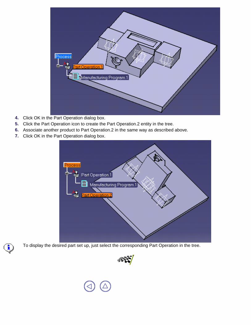
4. Click OK in the Part Operation dialog box.5. Click the Part Operation icon to create the Part Operation.2 entity in the tree.6. Associate another product to Part Operation.2 in the same way as described above.7. Click OK in the Part Operation dialog box.
To display the desired part set up, just select the corresponding Part Operation in the tree.

Workbench DescriptionThis section contains the description of the menu commands and icon toolbars that are specific to the Prismatic Machiningworkbench, which is shown below.
Menu BarToolbars
Specification Tree

CATIA Prismatic Machining Menu BarThe various menus and menu commands that are specific to Prismatic Machining aredescribed below.
Start File Edit View Insert Tools Windows Help
Tasks corresponding to general menu commands are described in the CATIA Version 5Infrastructure User's Guide.
Edit MenuPlease note that most of the edit commands available here are common facilities offered by theCATIA Version 5 Infrastructure.
The specific Prismatic Machining edit commands depend on the type of object being edited: Manufacturing Program or other entity.
Edit > Manufacturing Program.x object
Command... Description...Deactivate/Activate Deactivates the program
for replay or NC output. Itcan be made active againwith Activate.
Hide/Show Children Hides the child nodes ofthe program. They can bevisualized again withShow.
Replay Tool Path See Replay the Tool Path.Init Photo See Material Removal
Simulation.Refresh Photo See Material Removal
Simulation.Analyze Photo See Material Removal
Simulation.Photo Options See Material Removal
Settings.Generate NC Code See Generate NC Code
for the Program.Generate Tool Changes See Tool changes.

Delete Generated ToolChanges
See Tool changes.
Generate MachineRotations
See Machine Rotation.
Delete GeneratedMachine Rotations
See Machine Rotation.
APT Import See Import an APT file.
Edit > Part Operation.x object
Command... Description...Definition Accesses the Part Operation's definition
dialog box.Activate/Deactivate Deactivates the Part Operation. It can be
made active again.Show/Hide Children Hides the child nodes of the part
operation. They can be shown again.
Edit > Machining Operation.x object
Command... Description...Definition Accesses the operation's definition
dialog box.Deactivate/Activate Deactivates the operation for replay or
NC output. It can be made active again.Hide/Show Children Hides the child nodes of the operation.
They can be shown again.Replace Tool Allows replacing a tool on an operation.Replay Tool Path See Replay the Tool Path.
Edit > Manufacturing View.x object
Command... Description...
Sort by Features Sort the view by features.
Sort by Patterns Sort the view by patterns.
Sort by Activities Sort the view by operations.
Sort by Tools Sort the view by tools.

Insert MenuCommand... See...
Prismatic OperationsInsert > PrismaticOperations
Auxiliary OperationsInsert > AuxiliaryOperations
Machining FeaturesInsert > MachiningFeatures
Insert > Prismatic Operations
Command... See...Drilling Operations Creating Hole Making
Operations
PocketingCreating a PocketingOperation
Facing Creating a FacingOperation
Profile Contouring Creating a ProfileContouring Operation
Point to Point Creating a Point to PointOperation
Insert > Auxiliary Operations
Command... See...Tool Change Creating a ToolMachine Rotation Creating a Machine
RotationMachining Axis or Origin Creating a
Machining Axis

Post-Processor Instruction Creating a PPInstruction
Insert > Machining Features
Command... Description...Milling Features >Machining AxisSystem
Machining Axis System feature, which isreferenced in the machining axis ororigin auxiliary operation.
Machining Pattern Machining Pattern
Tools MenuPlease note that most of the Tools commands available here are common facilities offered bythe CATIA Version 5 Infrastructure.
Specific Prismatic Machining commands are described in the present document.Command... Description...Formula Allows editing parameters and
formula.Image Allows capturing images.
Macro Allows recording, running andediting macros.
Parent/ChildrenAllows viewing the parentsand children of a selectedobject.
Update Allows updating your session.
Customize Allows customizing theworkbench.
OptionsSee NC ManufacturingSettings.
Search Order Allows specifying a searchorder list.

CATIA Prismatic Machining ToolbarsThe Prismatic Machining workbench includes a number of specific icon toolbars, which aredescribed below.
Manufacturing Program ToolbarMachining Operations ToolbarAuxiliary Operations Toolbar
Tool Path Management ToolbarMachining Features Toolbar
Manufacturing Auxiliary Views ToolbarGeometry Selection Toolbars

Manufacturing Program ToolbarThis toolbar contains the following tools for creating manufacturing program and part operationentities.
See Part Operation
See Manufacturing Program

Prismatic Operations ToolbarThis toolbar contains the following commands to create and edit milling and axial machiningoperations.
See Create a Pocketing Operation
See Create a Facing Operation
See Create a Profile Contouring Operation
See Create a Point to Point Operation
See Create a Drilling Operation
See Create a Spot Drilling Operation
See Create a Drilling Dwell Delay Operation
See Create a Drilling Deep Hole Operation
See Create a Drilling Break Chips Operation
See Create a Tapping Operation
See Create a Reverse Threading Operation
See Create a Thread without Tap Head Operation
See Create a Boring Operation
See Create a Boring and Chamfering Operation
See Create a Boring Spindle Stop Operation
See Create a Reaming Operation
See Create a Counterboring Operation
See Create a Countersinking Operation
See Create a Chamfering Two Sides Operation
See Create a Back Boring Operation
See Create a T-Slotting Operation

See Create a Circular Milling Operation

Auxiliary Operations ToolbarThis toolbar contains the following tools for creating auxiliary operations in the program.
See Tool Change
See Machine Rotation
See Machining Axis System
See PP Instruction

Tool Path Management ToolbarThis toolbar contains the following tools to help you validate the tool path and generate NCoutput.
See Replay Tool Path
See Generate NC Output in Batch Mode
See Generate NC Output in Interactive Mode
See Generate NC Documentation

Machining Features ToolbarThis toolbar contains the following tools for managing machining features.
Machining Axis System.
See Machining Patterns.

Auxiliary Manufacturing Views ToolbarThis toolbar contains the following tools to help you manage auxiliary manufacturing views.
See Manufacturing View described in Machining Patterns.
You can use the following commands on the Manufacturing View entity:sort by featuressort by activitiessort by patternssort by tools.
Import Tools. See procedure for searching tools described in Select or Createa Tool.

Geometry Selection ToolbarsThe toolbar below contains commands to help you select edges of contours when specifyinggeometry in machining operations.
Navigates tangentially on edges
Closes the contour with a line
Inserts lines on gaps
Resets all selections
Exits geometry selection mode.
Cancels any already selected geometry.
The toolbar below contains commands to help you select faces when specifying geometry inmachining operations.
Navigates on faces
Previews contours
Resets all selections
Exits geometry selection mode.
Cancels any already selected geometry.

Specification Tree Here is an example of a Process Product Resources specification tree for PrismaticMachining.
Process Product Resources (PPR) tree:The ProcessList is a plan that gives allthe activities and machining operationsrequired to transform a part from a roughto a finished state.The Part Operation defines themanufacturing resources and thereference data.The Manufacturing Program is the list ofall of the operations and tool changesperformed.
Pocketing.1 operation is completeand has been computed.Pocketing.3 operation is completebut has not been computed.Pocketing.2 operation has notbeen computed and does not haveall of the necessary data (indicatedby the exclamation point).
The ProductList gives all of the parts tomachine.The ResourcesList gives all of the toolsthat can be used in the program.

CustomizingThe tasks in this section describe ways in which you can customize your CATIA NCManufacturing environment.
NC Manufacturing SettingsTools Catalog
PP Word SyntaxesNC Documentation
Material Simulation Settings

NC Manufacturing SettingsThis task briefly describes which settings you can customize.
For more information, see Settings for NC Manufacturing products.1. Select Tools > Options from the menu bar.
2. Select the NC Manufacturing category in the tree to the left.
The options for NC Manufacturing settings appear. They are organized in tab pages and allow you tocustomize:
Display settingsthe display of the specification treethe tool display during tool path replay.the colors of displayed geometry and parametersthe creation of a CATPart at Product level for storing geometry that is necessary for NCmanufacturing
Resources settingsthe path of the folder containing tools catalogs and PP tablesthe selection of tools
Operations settingsthe use of default values for operation creationthe creation of machining operationsthe duplication of geometry links when copying
Output settingsthe selection of PP parameter files from different suppliers.
3. Click OK to apply the settings and quit the dialog box.

Tools CatalogThis task shows you how to build a customized tools catalog.
You will have to customize an Excel file and a VB macro file in order to build your tools catalog.1. Edit an Excel file with the desired tool descriptions.
The characteristic attributes of each tool type are described in Tools.You can include user-defined tool representations in your catalog. You do this by associating a CATPartdocument containing this representation to the desired tool in the last column of the Excel file.
The user-defined tool representation will be displayed in the tool path replay.2. Save the tool descriptions as a csv type file.3. Edit the VB macro file to specify the input and output files. An example is shown below:
'''''''''''''''''''''''''''''''''''''''''''''''''''''''''''' VBScript for Manufacturing Tools catalog generation.''''''''''''''''''''''''''''''''''''''''''''''''''''''''''
Language="VBSCRIPT"
Sub CATMain()csvFile ="MyCatalog.csv"catalogFile ="MyCatalog.catalog"
'Get the outputDir and inputDir environment variablesinputDir = "HOME\Catalog"outputDir = "HOME\Catalog"
'Creates a catalog documentDim Catlg As DocumentSet Catlg=CATIA.Documents.Add("CatalogDocument")
InitData1=inputDir & "\" & csvFileNewcata1=outputDir & "\" & catalogFile
'Calls CreateCatalogFromcsv method on Catlg (ENDCHAPTER)
Catlg.CreateCatalogFromcsv InitData1 , Newcata1
Catlg.Close
End Sub

4. In your Version 5 CATIA session, select Tool >Macro > Macros.
The Macro dialog box is displayed.
5. Select the VB macro file that you editedpreviously, then click Run.
The tools catalog is created (MyCatalog.catalog) along with a report file (MyCatalog.report).
You can check this in the Search Tool dialog box.

PP Word SyntaxesThis section shows you how to customize the following types of syntaxes in your PP word table:
syntaxes associated to NC commandssequences of PP word syntaxes associated to NC instructions.
The CATIA NC Manufacturing product will resolve the parameters of these syntaxes and syntax sequences andgenerate the corresponding statements in the APT output.
A sample PP word table is delivered with the product in \Startup\Manufacturing\PPTables\PPTableSample.pptable
It can be used as a basis for creating user-defined tables.
Please refer to PP Tables and Word Syntaxes for more information.
1. NC Commands
You can define for a given machine tool (i.e post-processor) PP word syntaxes associated to particular NCcommands.
An NC command is a machine function such as feedrate declaration (NC_FEEDRATE) or spindle activation(NC_SPINDLE_START).
A syntax comprises a major word and one or more syntax elements such as minor words, numerical values, listvalues and parameters.
A syntax that includes lists or parameters is a parameterized syntax (see example below):
*START_NC_COMMAND NC_FEEDRATEFEDRAT/%MFG_FEED_VALUE,&MFG_FEED_UNIT*END
Note that the `&' character indicates a list and the `%' character indicates a parameter.
You can define only one syntax for each NC command.The following example shows how the NC command NC_DELAY could be used in a Drilling Dwell Delayoperation.
2. Make sure that the PP word table is referenced by the machine used in the Part Operation and the syntaxassociated with the NC_DELAY command is already created as follows:
*START_NC_COMMAND NC_DELAYDELAY/&MFG_DELAY_UNIT,%MFG_DELAY_VALUE*END
3. Create a Drilling Dwell Delay operation. 4. In the dialog box showing the available options, set the Dwell mode to Revolutions and enter a numerical dwell
value of `5'.
In this case the statement generated in the resulting APT source will be:DELAY/REV,5.000
If the operation was created with the Dwell mode set to Time Units and a dwell value of `5', the statementgenerated in the resulting APT source would be:DELAY/5.000

1. NC Instructions
You can define for a given machine tool (i.e post-processor) sequences of PP word syntaxes associated toparticular NC instructions.
NC instructions are either axial machining operations or auxiliary commands.
A syntax comprises a major word and one or more syntax elements such as minor words, numerical values andstandard parameters. A set of standard parameters is associated to each NC instruction. Parameters may becombined in arithmetical expressions.
A syntax that includes parameters is a parameterized syntax (see example below):
*START_NC_INSTRUCTION NC_TOOL_CHANGE*START_SEQUENCETOOLNO/%MFG_TOOL_NUMBER,%MFG_NOMINAL_DIAMTPRINT/%MFG_TOOL_NAMELOADTL/%MFG_TOOL_NUMBER*END*END
Note that the `%' character indicates a parameter.
You can define one or more syntax sequences for each NC instruction.The following example shows how the NC instruction NC_DRILLING_DWELL_DELAY could be used togenerate a specific NC data output.
2. Make sure that the PP word table is referenced by the machine used in the Part Operation and the syntaxassociated with NC_DRILLING_DWELL_DELAY instruction is already created as follows:
*START_NC_INSTRUCTION NC_TOOL_CHANGE*START_SEQUENCECYCLE / DRILL, %MFG_TOTAL_DEPTH, %MFG_FEED_MACH_VALUE, &MFG_FEED_UNIT,%MFG_CLEAR_TIP, DWELL, %MFG_DWELL_REVOL*END*END
3. Create a Drilling Dwell Delay operation.4. In the dialog box showing the available options, set:
hole depth to 25.0feedrate to 500.0approach clearance to 5.0Dwell mode to Revolutions and enter a numerical dwell value of `3'.
In this case the NC data output is as follows:
CYCLE/DRILL, 25.000000, 500.000000, MMPM, 5.000000, DWELL, 3
The PP word table is updated with your syntaxes when you save the file.

NC DocumentationThis task shows you how to generate customized NC documentation.
You will have to customize a VBScript macro file according to the document that you want to generate.You can use the following scripting languages, depending on the platform you are running on:
BasicScript 2.2 SDK for UNIX (BasicScript is a registered trademark of Summit Software Company)VBScript, short for Visual Basic Scripting Edition, for Windows NT (Visual Basic is a registered trademark ofMicrosoft Corporation).
Users on NT machines must have Windows Scripting Host installed.
1. Open a sample delivered with the product from \Startup\Manufacturing\Documentation.
2. Open the document delivered with the product in\Startup\Manufacturing\Documentation\NCDocumentationReadMe.htm.
This document describes the interfaces to help you to produce NC manufacturing documentation.3. Modify the sample according to the type of document you want.4. Generate the documentation as described in Generate NC Documentation.

Material Simulation SettingsThis task shows you how to customize settings for material removal simulation.
1. Select the Photo Settings icon in the Material Removal Simulation Photo mode section of the Tool PathReplay dialog box.
The Settings dialog box appears that allows you to set options for the Photo mode.In the Faults tab you can customize:
the colors in which the faults on the workpiece will be displayed after a machined part/design partcomparison. the appearance of the fault indicator bounding box.
In the General tab you can customize:the colors of the tools used for machiningthe machining accuracy the size of the workpiece scooped out.
2. In the Faults tab, select the desired colors to bedisplayed for machining that is within tolerance andfor tool clashes.
3. For a particular type of fault, select thedesired tolerance range (for example, Tol and Tol X2) from the combo box and select its colorrepresentation in the adjacent combo box.
Tol represents the tolerance value that you specifiedin the Material Removal Simulation - Errors dialogbox.
4. In the Indicator section, select:the Solid button to display a transparentcuboid Indicator bounding box. You can alsovary the amount of transparency.the Wireframe button to display a wireframeIndicator bounding box.
The color of the bounding box may be modified tosuit the workpiece color to ensure adequate visibility.
These colors will be reflected on the workpiecewherever the tools have been used to cut materialon the workpiece.

5. In the General tab, if the machining resolution ischanged from coarse to fine, machining accuracyimproves and results in a very detailed machining.
However, a "fine" resolution results in more memoryand time being consumed for machining.
The Close-up options are not used in this version.
6. Click OK to quit Material Removal Settings andreturn to the Replay dialog box.

Reference InformationThis section provides essential reference information on the following topics.
ToolsNC Macros
PP Tables and PP Word SyntaxesAPT Formats

ToolsAll supported tool types as well as their characteristic attributes are presented in this section.
These attributes are particularly useful for tasks such as Building a catalog of tools.
Face Mill
The MFG_NAME_BAS attribute for this tool isMfgFaceMillTool
Symbols and corresponding geometry attributes used in this illustrationare:
MFG_NOMINAL_DIAM: DMFG_OUTSIDE_DIAM: DaMFG_OVERALL_LGTH: LMFG_LENGTH: lMFG_CUT_LENGTH: lcMFG_CORNER_RAD: RcMFG_BODY_DIAM: DbMFG_CUT_ANGLE: Kr
End Mill
The MFG_NAME_BAS attribute for this tool isMfgEndMillTool
Symbols and corresponding geometry attributes used in this illustrationare:
MFG_NOMINAL_DIAM: DMFG_OVERALL_LGTH: LMFG_LENGTH: lMFG_CUT_LENGTH: lcMFG_CORNER_RAD: RcMFG_BODY_DIAM: Db
Center Drill
The MFG_NAME_BAS attribute for this tool isMfgCenterDrillTool
Symbols and corresponding geometry attributes used in this figure are:MFG_NOMINAL_DIAM: DMFG_OVERALL_LGTH: LMFG_LENGTH: lMFG_BODY_DIAM: DbMFG_CUT_LENGTH: lcMFG_CUT_ANGLE: a1MFG_TAPER_ANGLE: a2

Spot Drill
The MFG_NAME_BAS attribute for this tool isMfgSpotDrillTool
Symbols and corresponding geometry attributes used in this figure are:MFG_NOMINAL_DIAM: DMFG_OVERALL_LGTH: LMFG_LENGTH: lMFG_BODY_DIAM: DbMFG_CUT_ANGLE: a
Drill
The MFG_NAME_BAS attribute for this tool isMfgDrillTool
Symbols and corresponding geometry attributes used in this figure are:MFG_NOMINAL_DIAM: DMFG_OVERALL_LGTH: LMFG_LENGTH: lMFG_BODY_DIAM: DbMFG_CUT_LENGTH: lcMFG_CUT_ANGLE: aMFG_TL_TIP_LGTH: ld
Countersink
The MFG_NAME_BAS attribute for this tool isMfgCountersinkTool
Symbols and corresponding geometry attributes used in this figure are:MFG_NOMINAL_DIAM: DMFG_OUTSIDE_DIAM: DaMFG_OVERALL_LGTH: LMFG_LENGTH: lMFG_BODY_DIAM: DbMFG_CUT_LENGTH: lcMFG_CUT_ANGLE: aMFG_ENTRY_DIAM: d
Reamer

The MFG_NAME_BAS attribute for this tool isMfgReamerTool
Symbols and corresponding geometry attributes used in this figure are:MFG_NOMINAL_DIAM: DMFG_OVERALL_LGTH: LMFG_LENGTH: lMFG_BODY_DIAM: DbMFG_CUT_LENGTH: lcMFG_ENTRY_DIAM: dMFG_TL_TIP_LGTH: ld
Boring Bar
The MFG_NAME_BAS attribute for this tool isMfgBoringBarTool
Symbols and corresponding geometry attributes used in this figure are:MFG_NOMINAL_DIAM: DMFG_OVERALL_LGTH: LMFG_LENGTH: lMFG_BODY_DIAM: DbMFG_CUT_LENGTH: lcMFG_CUT_ANGLE: aMFG_NON_CUT_DIAM: dnMFG_TIP_LENGTH: ltMFG_TIP_ANGLE: eMFG_TIP_RADIUS: ReMFG_TOOL_ANGLE: bMFG_TL_TIP_LGTH: ld
Tap
The MFG_NAME_BAS attribute for this tool isMfgTapTool
Symbols and corresponding geometry attributes used in this figure are:MFG_NOMINAL_DIAM: DMFG_OVERALL_LGTH: LMFG_LENGTH: lMFG_BODY_DIAM: DbMFG_CUT_LENGTH: lcMFG_ENTRY_DIAM: dMFG_TL_TIP_LGTH: ld

T-Slotter
The MFG_NAME_BAS attribute for this tool isMfgTSlotterTool
Symbols and corresponding geometry attributes used in this figure are:MFG_NOMINAL_DIAM: DMFG_OVERALL_LGTH: LMFG_LENGTH: lMFG_CORNER_RAD: RcMFG_BODY_DIAM: DbMFG_CORNER_RAD_2: Rc2
Multi-Diameter Drill
The MFG_NAME_BAS attribute for this tool isMfgMultiDiamDrillTool
Symbols and corresponding geometry attributes used in this figure are:MFG_NOMINAL_DIAM: DMFG_OVERALL_LGTH: LMFG_LENGTH: lMFG_CUT_LENGTH: lcMFG_BODY_DIAM: DbMFG_CUT_ANGLE: a1MFG_TAPER_ANGLE: a3MFG_TL_TIP_LGTH: ldMFG_LENGTH_1: l1MFG_LENGTH_2: l2MFG_ANGLE_2: a2MFG_CHAMFR_DIAM1: DcMFG_CHAMFR_DIAM2: Dc2
Two Sides Chamfering Tool
The MFG_NAME_BAS attribute for this tool isMfgTwoSidesChamferingTool
Symbols and corresponding geometry attributes used in this figure are:MFG_NOMINAL_DIAM: DMFG_OVERALL_LGTH: LMFG_LENGTH: lMFG_CUT_LENGTH: lcMFG_BODY_DIAM: DbMFG_CUT_ANGLE: a1MFG_TL_TIP_LGTH: ldMFG_ENTRY_DIAM: dMFG_ANGLE_2: a2

Boring and Chamfering Tool
The MFG_NAME_BAS attribute for this tool isMfgBoringAndChamferingTool
Symbols and corresponding geometry attributes used in this figure are:MFG_NOMINAL_DIAM: DMFG_OVERALL_LGTH: LMFG_LENGTH: lMFG_CUT_LENGTH: lcMFG_CORNER_RAD: RcMFG_BODY_DIAM: DbMFG_LENGTH_1: l1MFG_CHAMFR_DIAM1: DcMFG_TAPER_ANGLE: a
Conical Mill
The MFG_NAME_BAS attribute for this tool isMfgConicalMillTool
Symbols and corresponding geometry attributes used in this illustrationare:
MFG_NOMINAL_DIAM: DMFG_OVERALL_LGTH: LMFG_LENGTH: lMFG_CUT_LENGTH: lcMFG_CORNER_RAD: RcMFG_BODY_DIAM: DbMFG_ENTRY_DIAM: dMFG_CUT_ANGLE: a

NC MacrosCATIA NC Macros in Machining OperationsThe following table shows which macro types you can define in the various types of machiningoperation.
Macros are optional but are very useful for providing approach and retract transition paths inyour operations.
Operation Approach Retract LinkingReturn
on SameLevel
Return betweenLevels
Return to Finish
PassClearance
Pocketing Yes Yes Yes Yes Yes Yes YesContouring Yes Yes Yes Yes Yes Yes YesFacing Yes Yes Yes Yes Yes Yes YesPoint to Point Yes Yes No No No No NoAxial Machining Yes Yes Yes No No No NoCircular Milling Yes Yes No Yes Yes No No
Approach Macro An Approach macro is used to approach the operation start point.
Retract Macro A Retract macro is used to retract from the operation end point.
Linking Macro A Linking macro may used in several cases, for example:
to avoid islands in Pocketing operationsto link two non consecutive pathsto access finish and spring passes in Pocketing and Contouring operationsto link points of a pattern in an axial machining operation.
You could define a Linking macro to do the following:Retract along the tool axis at machining or finishing feedrate up to a safety plane definedby the top plane plus an approach clearance.
1.
Approach next path along the tool axis with approach feedrate.2.

The clearance motion between the retract and approach is along a line in the safety planeat rapid feedrate.
3.
Return on Same Level MacroA Return on Same Level macro is used in a level to link two consecutive paths of a multi-pathoperation.
For example, you could define a Return on Same Level macro on a Profile Contouringoperation in One Way mode to do the following :
Retract along the tool axis at machining feedrate up to a safety plane defined by the topplane plus an approach clearance.
1.
Approach next path along the tool axis with approach feedrate.2. The clearance motion between the retract and approach is along a line in the safety planeat rapid feedrate.
3.
Note that no Return on Same Level macro is needed on a Profile Contouring operation in ZigZag mode. The motion between two paths is done at machining feedrate by following the profileof the boundary.
Return between Levels MacroA Return between Levels macro is used in a multi-level machining operation to go to the nextlevel.
You could define a Return between Levels macro to do the following:Retract along the tool axis at machining feedrate up to a safety plane defined by the topplane plus an approach clearance.
1.
Approach the next level along the tool axis at approach feedrate.2. The clearance motion between the retract and approach is along a line in the safety planeat rapid feedrate.
3.
Return to Finish Pass MacroA Return to Finish Pass macro is used in a machining operation to go to the finish pass.
For example, you could define a Return to Finish Pass macro to do the following:Retract along the tool axis at machining feedrate up to a safety plane defined by the topplane plus an approach clearance.
1.
Approach the finish pass level along the tool axis at approach feedrate.2. The clearance motion between the retract and approach is along a line in the safety planeat rapid feedrate.
3.

Clearance MacroA Clearance macro can be used in a machining operation to avoid a fixture, for example.
You could define a Clearance macro to do the following:Retract along the tool axis at machining feedrate up to a safety plane.1. Approach the finish pass level along the tool axis at approach feedrate.2. The clearance motion between the retract and approach is along a line in the safety planeat rapid feedrate.
3.

PP Tables and PP Word SyntaxesPP Word TablesYou can create and manage Post-Processor word tables with CATIA NC Manufacturing products.
A sample PP word table is delivered with the product, and can be used as a basis for creating user-defined tables. A PPword table is stored in a unique text file with suffix pptable.
A PP word table can be defined for a specific machine tool and used in CATIA NC applications. You can also define the general syntaxes of post-processor words. These syntaxes will be proposed when you want tocreate a PP instruction.
A PP word table comprises:major words without parametersmajor words with a textmajor words with parametersminor wordsword syntaxes.
You can define for a given machine tool:syntaxes associated to particular NC commandssequences of PP word syntaxes associated to particular NC instructions.
The CATIA NC Manufacturing product will resolve the parameters of these syntaxes and syntax sequences and generatethe corresponding statements in the APT output.
NC Commands You can define for a given machine tool (i.e. post-processor) PP word syntaxes associated to particular NC commands.
An NC command is a machine function such as feedrate declaration (NC_FEEDRATE) or spindle activation(NC_SPINDLE_START).
A syntax comprises a major word and one or more syntax elements such as minor words, numerical values, lists andparameters.
A syntax that includes lists or parameters is a parameterized syntax (see example below):
*START_NC_COMMAND NC_COMPENSATIONLOADTL/%MFG_TL_NUMBER,%MFG_TL_COMP*END
Note that the `&' character indicates a list and the `%' character indicates a parameter. A list has a finite number of values.
You can define only one syntax for each NC command.
For an example of how to define syntaxes in NC commands, please see PP Word Syntaxes in the Customizing section ofthis guide.
Syntaxes of NC Commands
NC command syntaxes that are supported in the current version are as follows.
NC_DELAY
MFG_DELAY_UNIT: list with two values defining the delay units.First value: delay expressed in number of revolutions.REV is the default value.Second value: delay expressed in seconds.A blank string (represented by 8 underscore characters) is the default value. When the statement is generated

by the application this string is ignored.MFG_DELAY_VALUE: numerical value of the delay.
NC_FEEDRATE
MFG_FEED_UNIT: list with two values defining the feedrate units.First value: feedrate expressed in model units per minute. MMPM is the default value.Second value: feedrate expressed in model units per revolution. MMPR is the default value.MFG_FEED_VALUE: numerical value of the feedrate.
NC_SPINDLE_ON
This syntax of this NC command is SPINDL/ON and cannot be parameterized.
NC_SPINDLE_START or NC_SPINDLE
MFG_SPNDL_UNIT: list with two values defining the spindle rotation units.First value: spindle rotation expressed in revolutions per minute. RPM is the default value.Second value: spindle rotation expressed in surface meters per minute. SMM is the default value.MFG_SPNDL_WAY: list with two values defining the direction of rotation of the spindle.First value: spindle rotation processed clockwise. CLW is the default value.Second value: spindle rotation processed counter-clockwise. CCLW is the default value.MFG_SPNDL_SPEED: numerical value of the spindle speed.MFG_SPNDL_DIAMTR: numerical value of the spindle diameter.
NC_SPINDLE_STOP
MFG_SPNDL_STOP: list with two values defining the action applied to the spindle.First value: de-activation of the spindle. OFF is the default value.Second value: spindle locked in an indexed position. LOCK is the default value.MFG_CMP_ANGLE: value of the indexation angle.
NC_SPINDLE_LOCK
This syntax of this NC command is SPINDL/LOCK and cannot be parameterized.
NC_SPINDLE_OFF
This syntax of this NC command is SPINDL/OFF and cannot be parameterized.
NC_COMPENSATION
MFG_TL_COMP: value of the tool compensation lengthMFG_TL_COMP_RAD: value of the tool compensation radiusMFG_TL_NUMBER: tool number associated to the compensation.MFG_TL_NAME: name of tool associated to the compensation
NC_COMMENT
MFG_MO_COMMENT: comment defined on machining operation.
NC_CUTCOM_ON
This syntax of this NC command is CUTCOM/ON and cannot be parameterized.
NC_CUTCOM_OFF
This syntax of this NC command is CUTCOM/OFF and cannot be parameterized.
NC_CUTCOM_LEFT
This syntax of this NC command is CUTCOM/LEFT and cannot be parameterized.
NC_CUTCOM_RIGHT
This syntax of this NC command is CUTCOM/RIGHT and cannot be parameterized.
NC_MACHINING_AXIS
This syntax of this NC command is as follows:

$$*CATIA0$$ %MFG_NCAXIS_IDENTIFIER$$ %MFG_NCAXIS_X_VECX %MFG_NCAXIS_X_VECY %MFG_NCAXIS_X_VECZ %MFG_NCAXIS_X_ORIG$$ %MFG_NCAXIS_Y_VECX %MFG_NCAXIS_Y_VECY %MFG_NCAXIS_Y_VECZ %MFG_NCAXIS_Y_ORIG$$ %MFG_NCAXIS_Z_VECX %MFG_NCAXIS_Z_VECY %MFG_NCAXIS_Z_VECZ %MFG_NCAXIS_Z_ORIG
The parameters are as follows:
MFG_NCAXIS_IDENTIFIER: machining axis identifierMFG_NCAXIS_X_ORIG, MFG_NCAXIS_Y_ORIG, MFG_NCAXIS_Z_ORIG: coordinates of the machining axisoriginMFG_NCAXIS_X_VECX, MFG_NCAXIS_Y_VECX, MFG_NCAXIS_Z_VECX: components of the x-axisMFG_NCAXIS_X_VECY, MFG_NCAXIS_Y_VECY, MFG_NCAXIS_Z_VECY: components of the y-axisMFG_NCAXIS_X_VECZ, MFG_NCAXIS_Y_VECZ, MFG_NCAXIS_Z_VECZ: components of the z-axis.
NC_MULTAX_ON
This syntax of this NC command is MULTAX and cannot be parameterized.
NC_MULTAX_OFF
This syntax of this NC command is MULTAX/OFF and cannot be parameterized.
NC Instructions You can define for a given machine tool (i.e post-processor) sequences of PP word syntaxes associated to particular NCinstructions.
NC instructions are either axial machining operations or auxiliary commands.
A syntax comprises a major word and one or more syntax elements such as minor words, numerical values and standardparameters. A set of standard parameters is associated to each NC instruction. Parameters may be combined inarithmetical expressions.
A syntax that includes parameters is a parameterized syntax (see examples below):
*START_NC_INSTRUCTION NC_TOOL_CHANGE*START_SEQUENCETOOLNO/%MFG_TOOL_NUMBER,%MFG_NOMINAL_DIAMTPRINT/%MFG_TOOL_NAMELOADTL/%MFG_TOOL_NUMBER*END*END
*START_NC_INSTRUCTION NC_TAPPING*START_SEQUENCECYCLE/TAP,%MFG_TOTAL_DEPTH,%MFG_CLEAR_TIP*END*END
Note that the `%' character indicates a parameter.
You can define one or more syntax sequences for each NC instruction.
For an example of how to define syntax sequences in NC Instructions, please see PP Word Syntaxes in the Customizingsection of this guide.
Standard Parameters for Auxiliary Command Type NC Instructions
These parameters include data defined on the corresponding entity or computed parameters which are calculatedaccording to an application method.
NC_START_MACRO
MFG_IDENTIFIER: Part Operation identifier

MFG_PROGRAM_NAME: Part Operation Program nameMFG_MACHINE_NAME: Machine name
NC_END_MACRO
MFG_IDENTIFIER: Part Operation identifierMFG_MACHINE_NAME: Machine name
NC_TABLE_ROTATION
MFG_TYPE_OF_ROT: Rotation type (absolute angle in this version)MFG_DIR_OF_ROT: Rotation direction (clockwise or counterclockwise)MFG_AMOUNT_ROT: Angle of rotation about the axis of rotationMFG_AXIS_OF_ROT: Axis of rotation on machine table. MFG_ABC_AXIS: Axis of rotation on machine table to get Minor word AAXIS, BAXIS or CAXIS.
NC_TOOL_CHANGE
Please note that in the following description 'tool assembly' means 'tool' or 'cutter' for the current version.
MFG_TL_ASMBLY_ID: Tool assembly identifier MFG_TL_SET_LGTH: Tool set lengthMFG_NOMINAL_DIAM: Nominal diameter of the toolMFG_TOOL_COMMENT: Comment associated with the toolMFG_TOOL_NUMBER: Tool assembly number MFG_ASS_COMMENT: Comment associated with the tool assemblyMFG_WEIGHT_SNTX: Tool weight syntaxMFG_COOLNT_SNTX: Coolant supply syntaxMFG_TOOTH_DES: Tooth descriptionMFG_DIAMETER_2: Diameter 2 of the tool assemblyMFG_MAX_MIL_TIME: Tool life (in time units)MFG_MAX_MIL_LGTH: Tool life (in length units)MFG_CORNER_RAD: Tool corner radiusMFG_CUT_ANGLE: Tool cutting angleMFG_LENGTH: Length of active part of the toolMFG_TL_TIP_LGTH: Tool tip lengthMFG_CUT_LENGTH: Tool cutting lengthMFG_NB_OF_FLUTES: Number of teethMFG_TOOL_NAME: Tool nameMFG_FEED_MACH: Machining feedrateMFG_SPNDL_MACH: Machining spindle speedMFG_TL_SET_X: Tool set length in x direction.MFG_TL_SET_Y: Tool set length in y direction.MFG_FEED_UNIT: Computed feedrate unitMFG_SPNDL_UNIT: Computed spindle speed unitMFG_WAY_OF_ROT: Computed rotation direction of tool (RIGHTHAND or LEFTHAND)MFG_TOOL_ASS_POW: Computed tool assembly power type (the value is MILL)MFG_TOOL_COMP: Computed tool compensationMFG_TOOL_COMP_2: Second computed tool compensation.
NC_ORIGIN
MFG_NCAXIS_X_ORIG, MFG_NCAXIS_Y_ORIG, MFG_NCAXIS_Z_ORIG: coordinates of the originMFG_ORIGIN_NUMBER: origin numberMFG_ORIGIN_GROUP: origin group.
Standard Parameters for Axial Machining Operation Type NC Instructions
For axial machining operations the standard parameters are either:tool guiding parameters or machinability data defined on the corresponding machining operationgeometrical data defined on the corresponding operation parameters that are calculated according to an application method.

Axial machining operation type NC Instructions are as follows.
NC_TAPPING
Feeds and Speeds parameters are as follows:
MFG_FEED_PLUNGE_MODE: Plunge feedrate modeMFG_FEED_PLUNGE_VALUE: Plunge feedrateMFG_FEED_MACH_VALUE: Machining feedrateMFG_SPINDLE_MACH_VALUE: Machining spindle speedMFG_FEED_RETRACT_MODE: Retract feedrate modeMFG_FEED_RETRACT_VALUE: Retract feedrate
Machining Strategy parameters are as follows:
MFG_CLEAR_TIP: Approach clearanceMFG_DEPTH_MODE: Depth modeMFG_BREAKTHROUGH: Breakthrough distanceMFG_TL_COMP: Tool compensation numberMFG_PLUNGE_MODE: Plunge modeMFG_PLUNGE_TIP: Plunge tip distanceMFG_PLUNGE_OFFST: Plunge tip offsetMFG_TOOL_COMP: Tool compensation.
Computed parameters are as follows:
MFG_DETAIL_DEPTH: Detail depthMFG_TOTAL_DEPTH:Total depthMFG_PLUNGE_DIST: Plunge distance
NC_THREAD_WITHOUT_TAP_HEAD
Feeds and Speeds parameters are as follows:
MFG_FEED_PLUNGE_MODE: Plunge feedrate modeMFG_FEED_PLUNGE_VALUE: Plunge feedrateMFG_FEED_MACH_VALUE: Machining feedrateMFG_SPINDLE_MACH_VALUE: Machining spindle speedMFG_FEED_RETRACT_MODE: Retract feedrate modeMFG_FEED_RETRACT_VALUE: Retract feedrate
Machining Strategy parameters are as follows:
MFG_CLEAR_TIP: Approach clearanceMFG_DEPTH_MODE: Depth modeMFG_BREAKTHROUGH: Breakthrough distanceMFG_TL_COMP: Tool compensation numberMFG_PLUNGE_MODE: Plunge modeMFG_PLUNGE_TIP: Plunge tip distanceMFG_PLUNGE_OFFST: Plunge tip offsetMFG_TOOL_COMP: Tool compensation.
Computed parameters are as follows:
MFG_DETAIL_DEPTH: Detail depthMFG_TOTAL_DEPTH:Total depthMFG_PLUNGE_DIST: Plunge distance
NC_REVERSE_THREADING
Feeds and Speeds parameters are as follows:
MFG_FEED_PLUNGE_MODE: Plunge feedrate modeMFG_FEED_PLUNGE_VALUE: Plunge feedrateMFG_FEED_MACH_VALUE: Machining feedrateMFG_SPINDLE_MACH_VALUE: Machining spindle speed

MFG_FEED_RETRACT_MODE: Retract feedrate modeMFG_FEED_RETRACT_VALUE: Retract feedrate
Machining Strategy parameters are as follows:
MFG_CLEAR_TIP: Approach clearanceMFG_DEPTH_MODE: Depth modeMFG_BREAKTHROUGH: Breakthrough distanceMFG_TL_COMP: Tool compensation numberMFG_PLUNGE_MODE: Plunge modeMFG_PLUNGE_TIP: Plunge tip distanceMFG_PLUNGE_OFFST: Plunge tip offsetMFG_TOOL_COMP: Tool compensation.
Computed parameters are as follows:
MFG_DETAIL_DEPTH: Detail depthMFG_TOTAL_DEPTH:Total depthMFG_PLUNGE_DIST: Plunge distance
NC_BORING
Feeds and Speeds parameters are as follows:
MFG_FEED_PLUNGE_MODE: Plunge feedrate modeMFG_FEED_PLUNGE_VALUE: Plunge feedrateMFG_FEED_MACH_VALUE: Machining feedrateMFG_SPINDLE_MACH_VALUE: Machining spindle speedMFG_FEED_RETRACT_MODE: Retract feedrate modeMFG_FEED_RETRACT_VALUE: Retract feedrate
Machining Strategy parameters are as follows:
MFG_CLEAR_TIP: Approach clearanceMFG_DEPTH_MODE: Depth modeMFG_BREAKTHROUGH: Breakthrough distanceMFG_TL_COMP: Tool compensation numberMFG_PLUNGE_MODE: Plunge modeMFG_PLUNGE_TIP: Plunge tip distanceMFG_PLUNGE_OFFST: Plunge tip offsetMFG_PLUNGE_DIAMETER: Plunge diameterMFG_DWELL_MODE: Dwell modeMFG_DWELL_REVOL: Dwell delay in revolutionsMFG_DWELL_TIME: Dwell delay in time units (seconds)MFG_TOOL_COMP: Tool compensation.
Computed parameters are as follows:
MFG_DETAIL_DEPTH: Detail depthMFG_TOTAL_DEPTH:Total depthMFG_PLUNGE_DIST: Plunge distanceMFG_CMP_DWL_TIME: Computed dwell delay
NC_BORING_SPINDLE_STOP
Feeds and Speeds parameters are as follows:
MFG_FEED_PLUNGE_MODE: Plunge feedrate modeMFG_FEED_PLUNGE_VALUE: Plunge feedrateMFG_FEED_MACH_VALUE: Machining feedrateMFG_SPINDLE_MACH_VALUE: Machining spindle speedMFG_FEED_RETRACT_MODE: Retract feedrate modeMFG_FEED_RETRACT_VALUE: Retract feedrate
Machining Strategy parameters are as follows:

MFG_CLEAR_TIP: Approach clearanceMFG_DEPTH_MODE: Depth modeMFG_BREAKTHROUGH: Breakthrough distanceMFG_TL_COMP: Tool compensation numberMFG_PLUNGE_MODE: Plunge modeMFG_PLUNGE_TIP: Plunge tip distanceMFG_PLUNGE_OFFST: Plunge tip offsetMFG_PLUNGE_DIAMETER: Plunge diameterMFG_DWELL_MODE: Dwell modeMFG_DWELL_REVOL: Dwell delay in revolutionsMFG_DWELL_TIME: Dwell delay in time units (seconds)MFG_LIFT_MODE: Shift mode MFG_XOFF: Shift along X MFG_YOFF: Shift along Y MFG_ZOFF: Shift along Z MFG_LIFT_ANGLE: Shift angle MFG_LIFT_DIST: Shift distanceMFG_TOOL_COMP: Tool compensation.
Computed parameters are as follows:
MFG_DETAIL_DEPTH: Detail depthMFG_TOTAL_DEPTH:Total depthMFG_PLUNGE_DIST: Plunge distanceMFG_CMP_DWL_TIME: Computed dwell delayMFG_CMP_OFFSET: Computed offsetMFG_CMP_ANGLE: Computed angle
NC_BACK_BORING
Feeds and Speeds parameters are as follows:
MFG_FEED_PLUNGE_MODE: Plunge feedrate modeMFG_FEED_PLUNGE_VALUE: Plunge feedrateMFG_FEED_MACH_VALUE: Machining feedrateMFG_SPINDLE_MACH_VALUE: Machining spindle speedMFG_FEED_RETRACT_MODE: Retract feedrate modeMFG_FEED_RETRACT_VALUE: Retract feedrate
Machining Strategy parameters are as follows:
MFG_CLEAR_TIP: Approach clearanceMFG_BREAKTHROUGH: Breakthrough distanceMFG_TL_COMP: Tool compensation numberMFG_DWELL_MODE: Dwell modeMFG_DWELL_REVOL: Dwell delay in revolutionsMFG_DWELL_TIME: Dwell delay in time units (seconds)MFG_LIFT_MODE: Shift mode MFG_XOFF: Shift along X MFG_YOFF: Shift along Y MFG_ZOFF: Shift along Z MFG_LIFT_ANGLE: Shift angle MFG_LIFT_DIST: Shift distanceMFG_TOOL_COMP: Tool compensation.
Computed parameters are as follows:
MFG_DETAIL_DEPTH: Detail depthMFG_TOTAL_DEPTH:Total depthMFG_PLUNGE_DIST: Plunge distanceMFG_CMP_DWL_TIME: Computed dwell delayMFG_CMP_OFFSET: Computed offsetMFG_CMP_ANGLE: Computed angle.

NC_BORING_AND_CHAMFERING
Feeds and Speeds parameters are as follows:
MFG_FEED_PLUNGE_MODE: Plunge feedrate modeMFG_FEED_PLUNGE_VALUE: Plunge feedrateMFG_FEED_MACH_VALUE: Machining feedrateMFG_SPINDLE_MACH_VALUE: Machining spindle speedMFG_FEED_RETRACT_MODE: Retract feedrate modeMFG_FEED_RETRACT_VALUE: Retract feedrate
Machining Strategy parameters are as follows:
MFG_CLEAR_TIP: Approach clearanceMFG_CLEAR_TIP_2: Second approach clearanceMFG_DEPTH_MODE: Depth modeMFG_BREAKTHROUGH: Breakthrough distanceMFG_CHAMFER_VAL: Chamfer valueMFG_TL_COMP: Tool compensation numberMFG_TL_COMP_2: Second tool compensation numberMFG_PLUNGE_MODE: Plunge modeMFG_PLUNGE_TIP: Plunge tip distanceMFG_PLUNGE_OFFST: Plunge tip offsetMFG_PLUNGE_DIAMETER: Plunge diameterMFG_DWELL_MODE: Dwell modeMFG_DWELL_REVOL: Dwell delay in revolutionsMFG_DWELL_TIME: Dwell delay in time units (seconds)MFG_TOOL_COMP: Tool compensationMFG_TOOL_COMP_2: Second tool compensation.
Computed parameters are as follows:
MFG_DETAIL_DEPTH: Detail depthMFG_TOTAL_DEPTH:Total depthMFG_PLUNGE_DIST: Plunge distanceMFG_CMP_DWL_TIME: Computed dwell delay
NC_TWO_SIDES_CHAMFERING
Feeds and Speeds parameters are as follows:
MFG_FEED_PLUNGE_MODE: Plunge feedrate modeMFG_FEED_PLUNGE_VALUE: Plunge feedrateMFG_FEED_MACH_VALUE: Machining feedrateMFG_SPINDLE_MACH_VALUE: Machining spindle speedMFG_FEED_RETRACT_MODE: Retract feedrate modeMFG_FEED_RETRACT_VALUE: Retract feedrate
Machining Strategy parameters are as follows:
MFG_CLEAR_TIP: Approach clearanceMFG_CLEAR_TIP_2: Second approach clearanceMFG_DEPTH_MODE: Depth modeMFG_TL_COMP: Tool compensation numberMFG_TL_COMP_2: Second tool compensation numberMFG_PLUNGE_MODE: Plunge modeMFG_PLUNGE_TIP: Plunge tip distanceMFG_PLUNGE_OFFST: Plunge tip offsetMFG_PLUNGE_DIAMETER: Plunge diameterMFG_DWELL_MODE: Dwell modeMFG_DWELL_REVOL: Dwell delay in revolutionsMFG_DWELL_TIME: Dwell delay in time units (seconds)MFG_TOOL_COMP: Tool compensationMFG_TOOL_COMP_2: Second tool compensation.

Computed parameters are as follows:
MFG_DETAIL_DEPTH: Detail depthMFG_TOTAL_DEPTH:Total depthMFG_PLUNGE_DIST: Plunge distanceMFG_CMP_DWL_TIME: Computed dwell delay
NC_COUNTERBORING
Feeds and Speeds parameters are as follows:
MFG_FEED_PLUNGE_MODE: Plunge feedrate modeMFG_FEED_PLUNGE_VALUE: Plunge feedrateMFG_FEED_MACH_VALUE: Machining feedrateMFG_SPINDLE_MACH_VALUE: Machining spindle speedMFG_FEED_RETRACT_MODE: Retract feedrate modeMFG_FEED_RETRACT_VALUE: Retract feedrate
Machining Strategy parameters are as follows:
MFG_CLEAR_TIP: Approach clearanceMFG_DEPTH_MODE: Depth modeMFG_TL_COMP: Tool compensation numberMFG_PLUNGE_MODE: Plunge modeMFG_PLUNGE_TIP: Plunge tip distanceMFG_PLUNGE_OFFST: Plunge tip offsetMFG_PLUNGE_DIAMETER: Plunge diameterMFG_DWELL_MODE: Dwell modeMFG_DWELL_REVOL: Dwell delay in revolutionsMFG_DWELL_TIME: Dwell delay in time units (seconds)MFG_TOOL_COMP: Tool compensation.
Computed parameters are as follows:
MFG_DETAIL_DEPTH: Detail depthMFG_TOTAL_DEPTH:Total depthMFG_PLUNGE_DIST: Plunge distanceMFG_CMP_DWL_TIME: Computed dwell delay
NC_COUNTERSINKING
Feeds and Speeds parameters are as follows:
MFG_FEED_PLUNGE_MODE: Plunge feedrate modeMFG_FEED_PLUNGE_VALUE: Plunge feedrateMFG_FEED_MACH_VALUE: Machining feedrateMFG_SPINDLE_MACH_VALUE: Machining spindle speedMFG_FEED_RETRACT_MODE: Retract feedrate modeMFG_FEED_RETRACT_VALUE: Retract feedrate
Machining Strategy parameters are as follows:
MFG_CLEAR_TIP: Approach clearanceMFG_DEPTH_MODE: Depth modeMFG_TL_COMP: Tool compensation numberMFG_PLUNGE_MODE: Plunge modeMFG_PLUNGE_TIP: Plunge tip distanceMFG_PLUNGE_OFFST: Plunge tip offsetMFG_PLUNGE_DIAMETER: Plunge diameterMFG_DWELL_MODE: Dwell modeMFG_DWELL_REVOL: Dwell delay in revolutionsMFG_DWELL_TIME: Dwell delay in time units (seconds)MFG_TOOL_COMP: Tool compensation.
Computed parameters are as follows:

MFG_DETAIL_DEPTH: Detail depthMFG_TOTAL_DEPTH:Total depthMFG_PLUNGE_DIST: Plunge distanceMFG_CMP_DWL_TIME: Computed dwell delay
NC_DRILLING_DWELL_DELAY
Feeds and Speeds parameters are as follows:
MFG_FEED_PLUNGE_MODE: Plunge feedrate modeMFG_FEED_PLUNGE_VALUE: Plunge feedrateMFG_FEED_MACH_VALUE: Machining feedrateMFG_SPINDLE_MACH_VALUE: Machining spindle speedMFG_FEED_RETRACT_MODE: Retract feedrate modeMFG_FEED_RETRACT_VALUE: Retract feedrate
Machining Strategy parameters are as follows:
MFG_CLEAR_TIP: Approach clearanceMFG_DEPTH_MODE: Depth modeMFG_BREAKTHROUGH: Breakthrough distanceMFG_TL_COMP: Tool compensation numberMFG_PLUNGE_MODE: Plunge modeMFG_PLUNGE_TIP: Plunge tip distanceMFG_PLUNGE_OFFST: Plunge tip offsetMFG_PLUNGE_DIAMETER: Plunge diameterMFG_DWELL_MODE: Dwell modeMFG_DWELL_REVOL: Dwell delay in revolutionsMFG_DWELL_TIME: Dwell delay in time units (seconds)MFG_TOOL_COMP: Tool compensation.
Computed parameters are as follows:
MFG_DETAIL_DEPTH: Detail depthMFG_TOTAL_DEPTH:Total depthMFG_PLUNGE_DIST: Plunge distanceMFG_CMP_DWL_TIME: Computed dwell delay
NC_BREAK_CHIPS
Feeds and Speeds parameters are as follows:
MFG_FEED_PLUNGE_MODE: Plunge feedrate modeMFG_FEED_PLUNGE_VALUE: Plunge feedrateMFG_FEED_MACH_VALUE: Machining feedrateMFG_SPINDLE_MACH_VALUE: Machining spindle speedMFG_FEED_RETRACT_MODE: Retract feedrate modeMFG_FEED_RETRACT_VALUE: Retract feedrate
Machining Strategy parameters are as follows:
MFG_CLEAR_TIP: Approach clearanceMFG_DEPTH_MODE: Depth modeMFG_BREAKTHROUGH: Breakthrough distanceMFG_AXIAL_DEPTH: Axial depthMFG_OFFSET_RET: Retract offset MFG_TL_COMP: Tool compensation numberMFG_PLUNGE_MODE: Plunge modeMFG_PLUNGE_TIP: Plunge tip distanceMFG_PLUNGE_OFFST: Plunge tip offsetMFG_PLUNGE_DIAMETER: Plunge diameterMFG_DWELL_MODE: Dwell modeMFG_DWELL_REVOL: Dwell delay in revolutionsMFG_DWELL_TIME: Dwell delay in time units (seconds)

MFG_TOOL_COMP: Tool compensation.
Computed parameters are as follows:
MFG_DETAIL_DEPTH: Detail depthMFG_TOTAL_DEPTH:Total depthMFG_PLUNGE_DIST: Plunge distanceMFG_CMP_DWL_TIME: Computed dwell delayMFG_EFFCT_DEPTH: Effective depth
NC_DEEPHOLE
Feeds and Speeds parameters are as follows:
MFG_FEED_PLUNGE_MODE: Plunge feedrate modeMFG_FEED_PLUNGE_VALUE: Plunge feedrateMFG_FEED_MACH_VALUE: Machining feedrateMFG_SPINDLE_MACH_VALUE: Machining spindle speedMFG_FEED_RETRACT_MODE: Retract feedrate modeMFG_FEED_RETRACT_VALUE: Retract feedrate
Machining Strategy parameters are as follows:
MFG_CLEAR_TIP: Approach clearanceMFG_DEPTH_MODE: Depth modeMFG_BREAKTHROUGH: Breakthrough distanceMFG_TL_COMP: Tool compensation numberMFG_PLUNGE_MODE: Plunge modeMFG_PLUNGE_TIP: Plunge tip distanceMFG_PLUNGE_OFFST: Plunge tip offsetMFG_PLUNGE_DIAMETER: Plunge diameterMFG_DWELL_MODE: Dwell modeMFG_DWELL_REVOL: Dwell delay in revolutionsMFG_DWELL_TIME: Dwell delay in time units (seconds)MFG_AXIAL_DEPTH: Axial depthMFG_OFFSET_RET: Retract offset MFG_DEPTH_DEC: Decrement limit MFG_DEPTH_LIM: Decrement rate MFG_TOOL_COMP: Tool compensation.
Computed parameters are as follows:
MFG_DETAIL_DEPTH: Detail depthMFG_TOTAL_DEPTH:Total depthMFG_PLUNGE_DIST: Plunge distanceMFG_CMP_DWL_TIME: Computed dwell delayMFG_EFFCT_DEPTH: Effective depth
NC_REAMING
Feeds and Speeds parameters are as follows:
MFG_FEED_PLUNGE_MODE: Plunge feedrate modeMFG_FEED_PLUNGE_VALUE: Plunge feedrateMFG_FEED_MACH_VALUE: Machining feedrateMFG_SPINDLE_MACH_VALUE: Machining spindle speedMFG_FEED_RETRACT_MODE: Retract feedrate modeMFG_FEED_RETRACT_VALUE: Retract feedrate
Machining Strategy parameters are as follows:
MFG_CLEAR_TIP: Approach clearanceMFG_DEPTH_MODE: Depth modeMFG_BREAKTHROUGH: Breakthrough distanceMFG_TL_COMP: Tool compensation number

MFG_PLUNGE_MODE: Plunge modeMFG_PLUNGE_TIP: Plunge tip distanceMFG_PLUNGE_OFFST: Plunge tip offsetMFG_PLUNGE_DIAMETER: Plunge diameterMFG_DWELL_MODE: Dwell modeMFG_DWELL_REVOL: Dwell delay in revolutionsMFG_DWELL_TIME: Dwell delay in time units (seconds)MFG_TOOL_COMP: Tool compensation.
Computed parameters are as follows:
MFG_DETAIL_DEPTH: Detail depthMFG_TOTAL_DEPTH:Total depthMFG_PLUNGE_DIST: Plunge distanceMFG_CMP_DWL_TIME: Computed dwell delay
NC_SPOT_DRILLING
Feeds and Speeds parameters are as follows:
MFG_FEED_PLUNGE_MODE: Plunge feedrate modeMFG_FEED_PLUNGE_VALUE: Plunge feedrateMFG_FEED_MACH_VALUE: Machining feedrateMFG_SPINDLE_MACH_VALUE: Machining spindle speedMFG_FEED_RETRACT_MODE: Retract feedrate modeMFG_FEED_RETRACT_VALUE: Retract feedrate
Machining Strategy parameters are as follows:
MFG_CLEAR_TIP: Approach clearanceMFG_DEPTH_MODE: Depth modeMFG_BREAKTHROUGH: Breakthrough distanceMFG_TL_COMP: Tool compensation numberMFG_PLUNGE_MODE: Plunge modeMFG_PLUNGE_TIP: Plunge tip distanceMFG_PLUNGE_OFFST: Plunge tip offsetMFG_PLUNGE_DIAMETER: Plunge diameterMFG_DWELL_MODE: Dwell modeMFG_DWELL_REVOL: Dwell delay in revolutionsMFG_DWELL_TIME: Dwell delay in time units (seconds)MFG_TOOL_COMP: Tool compensation.
Computed parameters are as follows:
MFG_DETAIL_DEPTH: Detail depthMFG_TOTAL_DEPTH:Total depthMFG_PLUNGE_DIST: Plunge distanceMFG_CMP_DWL_TIME: Computed dwell delay
NC_DRILLING
Feeds and Speeds parameters are as follows:
MFG_FEED_PLUNGE_MODE: Plunge feedrate modeMFG_FEED_PLUNGE_VALUE: Plunge feedrateMFG_FEED_MACH_VALUE: Machining feedrateMFG_SPINDLE_MACH_VALUE: Machining spindle speedMFG_FEED_RETRACT_MODE: Retract feedrate modeMFG_FEED_RETRACT_VALUE: Retract feedrate
Machining Strategy parameters are as follows:
MFG_CLEAR_TIP: Approach clearanceMFG_DEPTH_MODE: Depth modeMFG_BREAKTHROUGH: Breakthrough distance

MFG_TL_COMP: Tool compensation numberMFG_PLUNGE_MODE: Plunge modeMFG_PLUNGE_TIP: Plunge tip distanceMFG_PLUNGE_OFFST: Plunge tip offsetMFG_PLUNGE_DIAMETER: Plunge diameterMFG_TOOL_COMP: Tool compensation.
Computed parameters are as follows:
MFG_DETAIL_DEPTH: Detail depthMFG_TOTAL_DEPTH:Total depthMFG_PLUNGE_DIST: Plunge distance
NC_T_SLOTTING
Feeds and Speeds parameters are as follows:
MFG_FEED_PLUNGE_MODE: Plunge feedrate modeMFG_FEED_PLUNGE_VALUE: Plunge feedrateMFG_FEED_MACH_VALUE: Machining feedrateMFG_SPINDLE_MACH_VALUE: Machining spindle speedMFG_FEED_RETRACT_MODE: Retract feedrate modeMFG_FEED_RETRACT_VALUE: Retract feedrate
Machining Strategy parameters are as follows:
MFG_CLEAR_TIP: Approach clearanceMFG_DEPTH_MODE: Depth modeMFG_TL_COMP: Tool compensation numberMFG_DWELL_MODE: Dwell modeMFG_DWELL_REVOL: Dwell delay in revolutionsMFG_DWELL_TIME: Dwell delay in time units (seconds)MFG_TOOL_COMP: Tool compensation.
Computed parameters are as follows:
MFG_DETAIL_DEPTH: Detail depthMFG_TOTAL_DEPTH:Total depthMFG_PLUNGE_DIST: Plunge distanceMFG_CMP_DWL_TIME: Computed dwell delay
NC_CIRCULAR_MILLING
Feeds and Speeds parameters are as follows:
MFG_FEED_PLUNGE_MODE: Plunge feedrate modeMFG_FEED_PLUNGE_VALUE: Plunge feedrateMFG_FEED_MACH_VALUE: Machining feedrateMFG_SPINDLE_MACH_VALUE: Machining spindle speedMFG_FEED_RETRACT_MODE: Retract feedrate modeMFG_FEED_RETRACT_VALUE: Retract feedrate
Machining Strategy parameters include:
MFG_CLEAR_TIP: Approach clearanceMFG_TL_COMP: Tool compensation numberMFG_TOOL_COMP: Tool compensationMFG_RADIAL_STEP: Distance between pathsMFG_RADIAL_NB: Number of pathsMFG_AXIAL_STRAT: Axial modeMFG_AXIAL_DEPTH: Maximum depth of cutMFG_AXIAL_NUMBER: Number of levelsMFG_SEQUENCING_STRAT: Sequencing modeMFG_TOLER_MACH: Machining toleranceMFG_DIR_CUT: Direction of cut

MFG_OVERHANG: Percentage overlapMFG_DRAFT_ANGLE: Automatic draft angle.
Computed parameters are as follows:
MFG_DETAIL_DEPTH: Detail depthMFG_TOTAL_DEPTH:Total depth.

APT FormatsAPT Source OutputThis section describes formats used to write CATIA data on APT source files. Blank charactersused for presentation comfort on file are not mentioned. Example of format:'AUTOPS'
'INDIRV/',F11.5,',',F11.5,',',F11.5'
'TLON,GOFWD/ (CIRCLE/',F13.5,',',F13.5,',',F13.5,',$',T73,'CIR',I5
F13.5,'),ON,2,INTOF,$'
'(LINE/',F13.5,',',F13.5,',',F13.5,',$'
F13.5,',',F13.5,',',F13.5,')'
Example of Generated APT SourceAUTOPS
INDIRV/ 0.00000, -1.00000, 0.00000
TLON,GOFWD/ (CIRCLE/ 0.00000, 0.00000, 0.00000,$ CIR 1
50.00000),ON,2,INTOF,$
(LINE/ 0.00000, 0.00000, 0.00000,$
50.00000, 0.00000, 0.00000)
For each tool movement (GOTO, GODLTA, or CIRCLE, for example), the application generatesspecific information on the corresponding line to indicate the total number of points or circlesgenerated. For example, PT 22 or CIR 1. This information is written starting from column 73 inthe APT source file.
Syntax of APT Instructions Generated by theApplicationGeneral Information
'$$',70('=')
'$$',6X,'GENERATED ON ',A28,' AT ',A8 start of execution (date, time)
Operation Numbers

'PPRINT OPERATION NUMBER: ',I4
'$$ OPERATION NUMBER: ',I4 operation order number in part operation
PP or APT Word Instruction
A80 PP instruction string
NC Axis Components
'$$*CATIA0'
'$$ ',A70 NC axis identifier(may be blank if table rotation operation).
'$$ ',4(F11.5,2X)'$$ ',4(F11.5,2X)'$$ ',4(F11.5,2X) NC axis matrix definition in absolute axis (*axis1)
Model, Part Operation and Working Mode
'PPRINT MACHINE = ',A60 machine name (sub-string)
'PPRINT MODEL = ',A60 model name (sub-string)
'PPRINT PART OP = ',A60 part operation name (sub-string)
'TLAXIS/'F9.6,2(',',F9.6) tool axis components expressed in machining axissystem.
Starting Point Operation
'GOTO/',F11.5,2(',',F11.5),T73,'PT ',I5 tool tip coordinates, point number
'FROM/',F11.5,2(',',F11.5),T73,'PT ',I5 tool tip coordinates, point number
Tool Information
'PPRINT TOOL = ',A60 tool name (sub-string)
'CUTTER/',4(F10.6,','),F10.6,',$'
F10.6,',',F10.6
cutter diameter, corner radius, distance center corner to tool axis, cornerradius, 0.0
beta angle, height
Option Values
'INTOL /',F11.5 machining tolerance
'OUTTOL/',F11.5 0.0

Feedrate Values
'FEDRAT/',F10.4 feedrate values
'RAPID'
Linear Tool Motion
'GOTO/',F11.5,2(',',F11.5),T73,'PT ',I5 tool tip coordinates, point number
'GODLTA/',F11.5,2(',',F11.5),T73,'PT ',I5 tool tip incremental move, pointnumber
Circular Tool Motion - CIRCLE/
'AUTOPS' -
'INDIRV/',F11.5,',',F11.5,',',F11.5' components of circle tangent at arcstart pt
'TLON,GOFWD/ (CIRCLE/',F13.5,',',F13.5,',',F13.5,',$',T73,'CIR',I5 circlecenter coords, circle number
EITHER:
F13.5,'),ON,(LINE/',F13.5,',',F13.5,',',F13.5,',$' radius, circle center coords
OR:
F13.5,'),ON,2,INTOF,$' radius,
'(LINE/',F13.5,',',F13.5,',',F13.5,',$' circle center coords
F13.5,',',F13.5,',',F13.5,')' arc end point coords
Circular Tool Motion - CYLNDR/
'PSIS/(PLANE/(POINT/',F11.5,2(',',F11.5),'),PERPTO,$' tool tip coordinates
'(VECTOR/',2(F9.6,','),F9.6,'))' circle axis components
'(INDIRV/',F11.5,',',F11.5,',',F11.5) components of circle tangent at arcstart point
'TLON,GOFWD/(CYLNDR/',2(F11.5,','),F11.5,',$',T73,'CIR',I5 circle centercoordinates, circle number
EITHER:
3(F11.5,','),F11.5,'),ON,$' circle axis components, radius
OR:

3(F11.5,','),F11.5,'),ON,2,INTOF,$' circle axis components, radius
'(PLANE/PERPTO,$') -
'(PLANE/(POINT/',F11.5,2(',',F11.5),'),PERPTO,$' circle center coordinates
'(VECTOR/',2(F9.6,','),F9.6,')),$') circle axis components
'(POINT/',2(F11.5,','),F11.5,'),$') circle center coordinates
'(POINT/',2(F11.5,','),F11.5,'))' arc end point coordinates

GlossaryA
approachmacro
Motion defined for approaching the operation start point
auxiliarycommand
A control function such as tool change or machine table rotation. Thesecommands may be interpreted by a specific post-processor.
axialmachiningoperation
Operation in which machining is done along a single axis and is mainlyintended for hole making (drilling, counter boring, and so on).
Bback and forth Machining in which motion is done alternately in one direction then the other.
Compare with one way.bottom plane A planar geometric element that represents the bottom surface of an area to
machine. It is normal to the tool axis.
Cclearancemacro
Motion that involves retracting to a safety plane, a linear trajectory in that planeand then plunging from that plane.
climb milling Milling in which the advancing tool rotates down into the material. Chips of cutmaterial tend to be thrown behind the tool, which results to give good surfacefinish.Compare with conventional milling.
conventionalmilling
Milling in which the advancing tool rotates up into the material. Chips of cutmaterial tend to be carried around with the tool, which often impairs goodsurface finish.Compare with climb milling.
DDPM Digital Process for Manufacturing.
Eextensiontype
Defines the end type of a hole as being through hole or blind.

FFacingoperation
A surfacing operation in which material is removed in one cut or several axialcuts of equal depth according to a pre-defined machining strategy. Boundariesof the planar area to be machined are soft.
Fault Types of faults in material removal simulation are gouge, undercut, and toolclash.
feedrate Rate at which a cutter advances into a work piece.Measured in linear or angular units (mm/min or mm/rev, for example).
fixture Elements used to secure or support the workpiece on a machine.
Ggouge Area where the tool has removed too much material from the workpiece.
Hhard A geometric element (such as a boundary or a bottom face) that the tool
cannot pass beyond.
Iinward helical Machining in which motion starts from a point inside the domain to machine
and follows paths parallel to the domain boundary towards the centre of thedomain. Compare with outward helical.
Llinking motion Motion that involves retracting to a safety plane, a linear trajectory in that plane
and then plunging from that plane. M
machinerotation
An auxiliary command in the program that corresponds to a rotation of themachine table.
machiningaxis system
Reference axis system in which coordinates of points of the tool path aregiven.
machiningfeature
A feature instance representing a volume of material to be removed, amachining axis, tolerances, and other technological attributes. These featuresmay be hole type or milling type.
machiningoperation
Contains all the necessary information for machining a part of the workpieceusing a single tool.

machiningtolerance
The maximum allowed difference between the theoretical and computed toolpath.
manufacturingprocess
Defines the sequence of part operations necessary for the completemanufacture of a part.
manufacturingprogram
Describes the processing order of the NC entities that are taken into accountfor tool path computation: machining operations, auxiliary commands and PPinstructions.
manufacturingview
The set of machining features defined in the part operation.
multi-leveloperation
Milling operation (such as Pocketing or Profile Contouring) that is done in aseries of axial cuts.
Ooffset Specifies a virtual displacement of a reference geometric element in an
operation (such as the offset on the bottom plane of a pocket, for example). Compare with thickness.
one way Machining in which motion is always done in the same direction. Compare withzig zag or back and forth.
outwardhelical
Machining in which motion starts from a point inside the domain to machineand follows paths parallel to the domain boundary away from the centre of thedomain. Compare with inward helical.
Ppart operation Links all the operations necessary for machining a part based on a unique part
registration on a machine. The part operation links these operations with theassociated fixture and set-up entities.
pocket An area to be machined that is defined by a closed boundary and a bottomplane. The pocket definition may also include a top plane and one or moreislands.
Pocketingoperation
A machining operation in which material is removed from a pocket in one cut orseveral axial cuts of equal depth according to a pre-defined machiningstrategy.
The toolpath style is either inward helical or outward helical.
Boundaries of the pocket are hard.Point to Pointoperation
A milling operation in which the tool moves in straight line segments betweenuser-defined points.
PP instruction Instructions that control certain functions that are auxiliary to the tool-partrelationship. They may be interpreted by a specific post processor.
PPR Process Product Resources.

ProfileContouringoperation
A milling operation in which the tool follows a guide curve and possibly otherguide elements while respecting user-defined geometric limitations andmachining strategy parameters.
Rretract macro Motion defined for retracting from the operation end point
return macro Motion for linking between paths or between levels. It involves retracting to asafety plane, a linear trajectory in that plane and then plunging from thatplane.
Ssafety plane A plane normal to the tool axis in which the tool tip can move or remain a
clearance distance away from the workpiece, fixture or machine.set up Describes how the part, stock and fixture are positioned on the machine.
soft A geometric element (such as a boundary or a bottom face) that the tool canpass beyond.
spindle speed The angular speed of the machine spindle.Measured in linear or angular units (m/min or rev/min, for example).
stock Workpiece prior to machining by the operations of a part operation.
Tthickness Specifies a thickness of material to be removed by machining. Compare with
offset.top plane A planar geometric element that represents the top surface of an area to
machine. It is always normal to the associated tool's rotational axis.tool axis Center line of the cutter.
tool change An auxiliary command in the program that corresponds to a change of tool.
tool clash Area where the tool collided with the workpiece during a rapid move.
tool path The path that the center of the tool tip follows during a machining operation.
total depth The total depth including breakthrough distance that is machined in a holemaking operation.

Uundercut Area where the tool has left material behind on the workpiece.
Zzig zag Machining in which motion is done alternately in one direction then the other.
Compare with one way.

IndexA
Activate command analyze geometry approach macro APT Import command Auxiliary operations axial machining operations
BBack Boring operation Boring and chamfering tool Boring and Chamfering operation Boring bar Boring operation Boring Spindle Stop operation
CCenter drill Chamfering Two Sides operation Circular Milling operation clearance macro climb milling Conical mill conventional milling Counterboring operation Countersink Countersinking operation

DDeactivate command Delete Generated Tool Changes command Delete Generated Machine Rotations command Drill Drilling Break Chips operation Drilling Deephole operation Drilling Dwell Delay operation Drilling operation
EEdit Parameters dialog box End mill entry distance exit distance
FFace mill Facing operation
GGenerate Tool Changes command Generate Machine Rotations command
Hhard geometric element

Jjump distance
Mmachine rotation machining axis machining feature machining operation machining pattern machining tolerance manufacturing program manufacturing process milling operations Multi-diameter drill
NNC command
NC_COMMENT NC_COMPENSATION NC_CUTCOM_LEFT NC_CUTCOM_OFF NC_CUTCOM_ON NC_CUTCOM_RIGHT NC_DELAY NC_FEEDRATE NC_MACHINING_AXIS NC_MULTAX_ON NC_MULTAX_OFF NC_SPINDLE NC_SPINDLE_LOCK NC_SPINDLE_OFF NC_SPINDLE_ON NC_SPINDLE_START

NC_SPINDLE_STOP NC instruction (axial machining type)
NC_BACK_BORING NC_BORING NC_BORING_SPINDLE_STOP NC_BORING_AND_CHAMFERING NC_BREAK_CHIPS NC_CIRCULAR_MILLING NC_COUNTERBORING NC_COUNTERSINKING NC_DEEPHOLE NC_DRILLING NC_DRILLING_DWELL_DELAY NC_REAMING NC_REVERSE_THREADING NC_SPOT_DRILLING NC_T_SLOTTING NC_TAPPING NC_THREAD_WITHOUT_TAP_HEAD NC_TWO_SIDES_CHAMFERING
NC instruction (auxiliary command type) NC_END_MACRO NC_ORIGIN NC_START_MACRO NC_TABLE_ROTATION NC_TOOL_CHANGE
Oorigin

Ppart operation pattern Pocketing operation
Closed pockets Open pockets
Preview command Profile Contouring operation
Between a curve and surfaces Between two curves Between two planes
Point to Point operation PP instruction PP word table
RReamer Reaming operation retract macro return macro return between levels macro return on same level macro return to finish pass macro Reverse Threading operation
Ssoft geometric element Spot drill Spot Drilling operation

TTap Tapping operation Thread without Tap Head operation T-slotter T-slotting operation tool
Boring and chamfering tool Boring bar Conical mill Center drill Countersink compensation create edit Drill End mill Face mill Multi-diameter drill Reamer Spot drill Tap T-slotter Two sides chamfering tool
Two sides chamfering tool tool change Tool path replay tools catalog

Uundercut