discoveringmotion.doc - dan macisaacphysicsed.buffalostate.edu/.../lemoynephysics/rotation… ·...
TRANSCRIPT
Exploring Rotational Motion:The Rotary Motion Sensor, Rotational Kinematics, Rotational Dynamics
May 6, 2023
Print Your Name
______________________________________
Print Your Partners' Names
______________________________________
______________________________________
You will return this handout to the instructor at the end of the lab period.
Table of Contents0. Introduction 11. Activity #1: Becoming familiar with the Rotary Motion Sensor 42. Activity #2: Rotational kinematics 63. Activity #3: Rotational dynamics 84. When you are done with this lab… 13
0. IntroductionAbstract This section contains a brief introduction to rotational dynamics using analogies between motion in a straight line and rotation.
In previous lab activities, you have been concerned with linear dynamics. Linear dynamics is when things move in straight lines, sometimes speeding up or slowing down. The activities in this lab are concerned with rotational dynamics, in which something spins, sometimes speeding up or slowing down.
0.1 Angular displacement
To do linear dynamics, one must be able to specify precisely the location of an object. This is done by keeping track of the distance, in meters, of an object from an origin. For rotational dynamics, the dynamics of an object that is rotating, one must keep track of how much that object has rotated using the angle through which the object has rotated with respect to a starting point. This angle is referred to as the angular displacement ( ) of the object. The angle could be in degrees, but the formulae of rotational dynamics are much simpler if instead of degrees one uses radians. Furthermore, to keep track of whether an object is rotating counterclockwise or clockwise, we follow the convention that the angular displacement is positive if the object has rotated counterclockwise and negative if the object has rotated clockwise.
Activity #1 of these laboratory activities involves gaining familiarity with a device that measures the angular displacement of a rotating object in radians in exactly the same way the
Page 1 © Le Moyne Physics Faculty
InstructionsBefore lab, read the Introduction, and answer the Pre-Lab Questions on the last page of this handout. Hand in your answers as you enter the general physics lab.
radians = 180º

Exploring Rotational Motion
Motion Detector keeps track of the linear displacement of an object in meters. The new device is called a Rotary Motion Sensor (often referred to simply as the RMS).
0.2 Angular velocity
Once linear displacement, in meters, is established, linear dynamics proceeds to the rate of change of displacement, which is velocity in meters per second. Similarly, rotational dynamics proceeds to the rate of change of angular displacement, which is angular velocity ( ) and is measured in radians per second (rad/s). Precisely, if an object undergoes an angular displacement in a time interval t, the average angular velocity in the time interval t is defined as
.
Just as linear velocity v (in m/s) is the slope of the Displacement-Time graph, angular velocity (in rad/s) is the slope of the Angular Displacement-Time graph.
0.3 Angular acceleration
What comes next? You may have guessed it by now – it must be the counterpart of linear acceleration. In rotational motion the corresponding quantity is called the angular acceleration ( ). Angular acceleration is defined as the rate of change of angular velocity and has units radians/second per second (rad/s2). For a rotating object experiencing constant angular acceleration the angular acceleration is defined as
.
Graphically, if one were to plot the angular velocity as a function of time, then angular acceleration (in rad/s2) is the slope of the graph, just as linear acceleration (in m/s2) is the slope of the linear velocity graph.
Experience with angular velocity and angular acceleration is the subject of Activity #2.
0.4 Torque
Figure 1 The torque on a pulley due to a string wrapped around it
Just as force in newtons is a quantitatively precise measure of the strength of pushes and pulls, there is an analogous quantitatively precise measure of twisting. This quantity is called torque, which is measured in newton·meters. Whenever you see the word torque, just think of twist.
Page 2 © Le Moyne Physics Faculty

Exploring Rotational Motion
In your physics text you will find an explanation of how to calculate torque in any situation, but you do not need that complete explanation for this lab. What you do need to know is how much torque a string wrapped around a pulley exerts on the pulley. This is very easy to calculate: it is just the tension in the string multiplied by the radius of the pulley, but positive if the twist on the pulley is in the counter-clockwise direction and negative if the twist on the pulley is in the clockwise direction. See Figure 1.
0.5 The torque equation
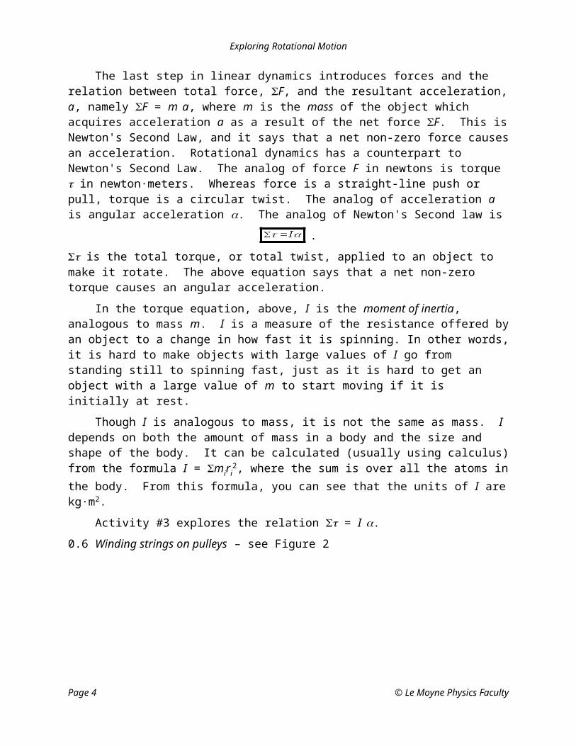
The last step in linear dynamics introduces forces and the relation between total force, F, and the resultant acceleration, a, namely F = m a, where m is the mass of the object which acquires acceleration a as a result of the net force F. This is Newton's Second Law, and it says that a net non-zero force causes an acceleration. Rotational dynamics has a counterpart to Newton's Second Law. The analog of force F in newtons is torque in newton·meters. Whereas force is a straight-line push or pull, torque is a circular twist. The analog of acceleration a is angular acceleration . The analog of Newton's Second law is
.
is the total torque, or total twist, applied to an object to make it rotate. The above equation says that a net non-zero torque causes an angular acceleration.
In the torque equation, above, I is the moment of inertia, analogous to mass m. I is a measure of the resistance offered by an object to a change in how fast it is spinning. In other words, it is hard to make objects with large values of I go from standing still to spinning fast, just as it is hard to get an object with a large value of m to start moving if it is initially at rest.
Though I is analogous to mass, it is not the same as mass. I depends on both the amount of mass in a body and the size and shape of the body. It can be calculated (usually using calculus) from the formula I = miri
2, where the sum is over all the atoms in the body. From this formula, you can see that the units of I are kg·m2.
Activity #3 explores the relation = I .
0.6 Winding strings on pulleys – see Figure 2
Figure 2 Winding strings on pulleys CCW and CW. This figure shows what is meant by winding a string CCW or CW on a pulley. Note that a string which is wound CCW will, when pulled, cause a CCW (hence positive) torque and, if there are no other torques, it causes a positive angular acceleration. A string wound CW does the opposite, causing a negative torque and a negative angular acceleration.
Page 3 © Le Moyne Physics Faculty
Exploring Rotational Motion
1. Activity #1: Becoming familiar with the Rotary Motion SensorAbstract : In this activity you are introduced to the Rotary Motion Sensor and learn how to use it with the Logger Pro software.
Equipment: ComputerULIII interface and Logger Pro (Version 1.1) laboratory softwareRotary Motion Sensor (RMS)Rotational motion accessory: three-step pulleyLogger Pro setup file RotationalMotion-Kinematics.MBL
1.1 Each station has a Rotary Motion Sensor ( Figure 3) mounted firmly on the table.
1.2 Connect the RMS to the socket marked PORT 2 on the interface box, and turn on the interface box. Make sure no other sensor is connected to the interface box.
1.3 Turn on the computer, and load Logger Pro.
1.4 Open the program file RotationalMotion-Kinematics.MBL.
1.4.1 You should see an empty Ang. Displacement (short for Angular Displacement) versus Time plot on your screen.
1.4.2 This file tells the Logger Pro software that a Rotary Motion Sensor has been connected to PORT 2 on the interface box, so that the software interprets the signals from PORT 2 correctly.
Plug for the Interface box
3-step pulley mounted on the RMS
Figure 3: The Rotary Motion Sensor (RMS)
1.4.3 Furthermore, the computer is now set to record and display the angular displacement versus time data at a rate of 20 samples/sec (that is, the computer records the angular displacement of a rotating object 20 times every second) for 10 seconds.
1.4.4 Best of all, the Rotary Motion Sensor requires no calibration.
1.5 The aim of this activity is to convince yourself that the RMS does indeed accurately measure the angular displacement of a rotating object.
Page 4 © Le Moyne Physics Faculty

Exploring Rotational Motion
Q 1 This is a theoretical question; do not use the lab equipment to answer it. If you rotate an object counterclockwise through exactly three full revolutions, what is its angular displacement with respect to the starting point, in radians? In answering this question, follow the convention that counterclockwise rotations are positive, and clockwise rotations are negative.
____________ radians
1.6 If you look closely at the three-step pulley mounted on the RMS, you will see that each of the pulleys on the three-step pulley has a groove and a hole. Align the groove on the largest pulley with the black line on the masking tape stuck to the RMS.
Masking tape with black line
Figure 4: Aligning the grooves on the pulley with the dark line on the masking tape
1.7 Click Collect on Logger Pro, wait for the red line to start moving left-to-right across the Logger Pro graph, and then smoothly rotate the three-step pulley counterclockwise through three revolutions with your finger tips. After three revolutions make sure that the grooves on the pulleys are precisely aligned with the dark line on the masking tape.
1.8 Use Logger Pro's Analyze-Examine Tool with the data collected by Logger Pro to determine the angular displacement measured by the RMS, and record the result here.
_______________ radians
1.9 If the value you obtained in 1.8 is not consistent with your answer to Q 1, consult with your lab instructor.
1.10 You can get Logger Pro to determine the Angular velocity of the pulley while you were rotating it. To obtain the Angular velocity versus Time plot:
1.10.1 Change the graph layout to Two Panes. You can do this by clicking on View on the main menu then choosing Graph Layout… and then choosing Two Panes.
1.10.2 Change the bottom plot to Angular velocity versus Time. Provide a proper title for the plot.
Page 5 © Le Moyne Physics Faculty
Give your answer as a decimal number, not as a multiple of .

Exploring Rotational Motion
Q 2 Use the data collected by Logger Pro to determine the sign on the angular velocity when the pulleys were rotating through 3 revolutions. What sign does Logger Pro have?
Q 3 This is a theoretical question; do not use the lab equipment to answer it. If you rotate the pulleys clockwise three revolutions, what will be the angle in radians? Be sure to include the correct sign.
1.11 Repeat paragraph 1.7, but rotate the pulleys on the RMS clockwise through 3 revolutions (instead of counter-clockwise). Fill in Table 1.
Predicted angular displacement, from Q 3 radians
Measured angular displacement (using Logger Pro data) radians
Sign on the Angular velocityTable 1
Make sure you are convinced that the RMS accurately measures the angular displacement of rotating objects. If you notice any discrepancy bring it to the attention of your lab instructor.
2. Activity #2: Rotational kinematicsAbstract: In this activity you will explore constant angular acceleration motion through Logger Pro plots.
Equipment: ComputerULIII interface and Logger Pro (Version 1.1) laboratory softwareRotary Motion Sensor (RMS)Rotational motion accessories: three-step pulley and metal diskPulley and stringSmall scissors (for cutting string)A 20 g massMeter stickLogger Pro setup file RotationalMotion-Kinematics.mbl
2.1 Delete the run, left over from Activity #1, that is displayed on your screen.
2.2 Revise the Logger Pro display
2.2.1 Change the graph layout to Three Panes.
2.2.2 Change the middle graph to Angular Velocity versus Time.
Page 6 © Le Moyne Physics Faculty

Exploring Rotational Motion
2.2.3 Change the bottom plot to Angular Acceleration versus Time.
2.3 Remove the screw on top of the three-step pulley, but leave the pulley in place.
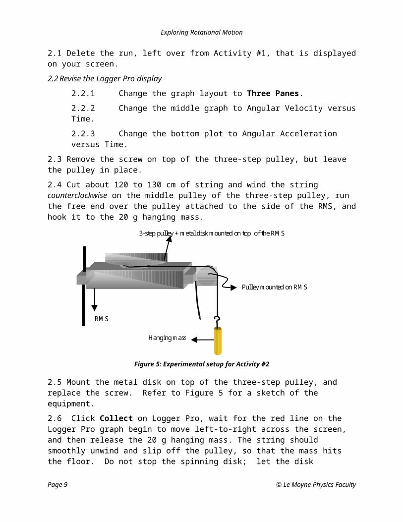
2.4 Cut about 120 to 130 cm of string and wind the string counterclockwise on the middle pulley of the three-step pulley, run the free end over the pulley attached to the side of the RMS, and hook it to the 20 g hanging mass.
Hanging mass
Pulley mounted on RMS
3-step pulley + metal disk mounted on top of the RMS
RMS
Figure 5: Experimental setup for Activity #2
2.5 Mount the metal disk on top of the three-step pulley, and replace the screw. Refer to Figure 5 for a sketch of the equipment.
2.6 Click Collect on Logger Pro, wait for the red line on the Logger Pro graph begin to move left-to-right across the screen, and then release the 20 g hanging mass. The string should smoothly unwind and slip off the pulley, so that the mass hits the floor. Do not stop the spinning disk; let the disk gradually spin to a stop. Logger Pro will display the data on the computer screen. Figure 6 shows you a sample data set.
III
Figure 6: A sample data set
2.7 Obtain printouts of your data. Each team member should have a printed copy of the data.
Page 7 © Le Moyne Physics Faculty

Exploring Rotational Motion
2.8 Refer to your printout to answer the following questions.
2.9 In your plots you should observe two approximately constant angular acceleration regions. Mark these two regions with the roman numeral I and II as shown in Figure 6.
Q 4 In region I, what are the signs of the angular velocity and the angular acceleration, and was the rotating pulley speeding up or slowing down?
Q 5 In region II, what are the signs of the angular velocity and the angular acceleration, and was the rotating pulley speeding up or slowing down? (If you are unable to determine the sign of the angular acceleration from the angular acceleration graph, look at the slope of the angular velocity graph.)
2.10 Wind the string clockwise around the pulley, and repeat steps 2.5 - 2.6 one more time.
2.11 Print the resulting Logger Pro graphs.
2.12 Refer to the data displayed on your screen to answer the following questions.
Q 6 In region I, what are the signs of the angular velocity and the angular acceleration, and was the rotating pulley speeding up or slowing down?
Q 7 In region II, what are the signs of the angular velocity and the angular acceleration, and was the rotating pulley speeding up or slowing down? (If you are unable to determine the sign of the angular acceleration from the angular acceleration graph, look at the slope of the angular velocity graph.)
2.13 When you are done with this activity, close the file RotationalMotion-Kinematics.mbl, but do not exit from Logger Pro. Please do not save anything on the hard drive.
Page 8 © Le Moyne Physics Faculty
Exploring Rotational Motion
3. Activity #3: Rotational dynamicsAbstract: Total torque and angular acceleration are related by = I , the rotational analog of Newton's Second Law, making the graph of torque versus angular acceleration a straight line with slope I.
Metal ring mounted on metal disk3-step pulley + metal disk mounted on RMS
Student Force Sensor
RMS
Pulley mounted on RMS
Hanging pulley + mass
Figure 7: Sketch of experimental setup for Activity #3
Equipment: ComputerULIII interface and Logger Pro (Version 1.1) laboratory softwareMS ExcelRotary Motion Sensor (RMS)Rotational motion accessories: three-step pulley, metal disk and metal ringStudent Force Sensor (SFS)Pulleys (3 of them; see Figure 7)StringScissors (to cut string)Digital caliper (for measuring diameters of pulleys)Masses: one 10 g, two 20 g, one 50 g, one 200 g, and one 500 gLogger Pro setup file RotationalMotion-Dynamics.mbl
3.1 Connect the Rotary Motion Sensor to the socket marked Port 2 on the interface box. Connect a Student Force sensor to the socket DIN 1 on the interface box.
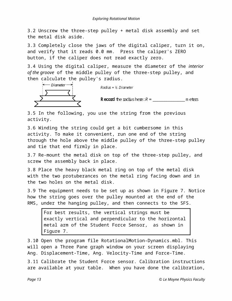
3.2 Unscrew the three-step pulley + metal disk assembly and set the metal disk aside.
3.3 Completely close the jaws of the digital caliper, turn it on, and verify that it reads 0.0 mm. Press the caliper's ZERO button, if the caliper does not read exactly zero.
Page 9 © Le Moyne Physics Faculty

Exploring Rotational Motion
3.4 Using the digital caliper, measure the diameter of the interior of the groove of the middle pulley of the three-step pulley, and then calculate the pulley's radius.
3.5 In the following, you use the string from the previous activity.
3.6 Winding the string could get a bit cumbersome in this activity. To make it convenient, run one end of the string through the hole above the middle pulley of the three-step pulley and tie that end firmly in place.
3.7 Re-mount the metal disk on top of the three-step pulley, and screw the assembly back in place.
3.8 Place the heavy black metal ring on top of the metal disk with the two protuberances on the metal ring facing down and in the two holes on the metal disk.
3.9 The equipment needs to be set up as shown in Figure 7. Notice how the string goes over the pulley mounted at the end of the RMS, under the hanging pulley, and then connects to the SFS.
For best results, the vertical strings must be exactly vertical and perpendicular to the horizontal metal arm of the Student Force Sensor, as shown in Figure 7.
3.10 Open the program file RotationalMotion-Dynamics.mbl. This will open a Three Pane graph window on your screen displaying Ang. Displacement-Time, Ang. Velocity-Time and Force-Time.
3.11 Calibrate the Student Force sensor. Calibration instructions are available at your table. When you have done the calibration, check to see that a 200 g weight yields a force of 1.96 N. If not, you must re-do the calibration.
3.12 Hang a 10 g mass from the hanging pulley
3.13 The instructions for conducting the experiment are similar to the instructions for Activity #2. Wind the string CCW on the middle pulley of the three-step pulley, and run the free end over the pulley attached to one end of the RMS, under the hanging pulley and to the SFS.
3.14 Click Collect on Logger Pro, wait for the red line on the Logger Pro graph to begin to move left-to-right across the screen, and let the string smoothly unwind. The data collected by Logger Pro will be displayed on your screen. Figure 8 shows a sample data set.
Page 10 © Le Moyne Physics Faculty

Exploring Rotational Motion
Figure 8: A sample data set
3.15 In your plots, identify the region that corresponds to constant angular acceleration motion when the hanging pulley + mass was falling towards the floor and the three-step pulley + metal disk + metal ring attachment was speeding up.
3.16 On your angular velocity-time plot, enclose the constant acceleration part of the motion (which you identified in 3.15) by left-clicking your mouse and dragging a rectangle around that region. Perform a linear fit on this region. Use the Analyze-Linear Fit tool on Logger Pro. The slope of the linear fit is the constant angular acceleration.
3.17 Determine the corresponding mean force from the Force-Time plot. Use the Analyze-Statistics Tool to do this. Record these values in Table 2.
Hanging mass
(grams)
Mean Force F (newtons)
Angular acceleration (rad/s2)
Torque = F·R
(N ·m)
10
20
30
40
50Table 2
3.18 To complete the column titled Torque in Table 2, multiply the mean force by the radius of the pulley.
3.19 Repeat steps 3.13-3.18 for four more hanging masses: 20 g, 30 g, 40 g and 50 g.
3.20 The next step is to plot a graph of torque versus angular acceleration.
Page 11 © Le Moyne Physics Faculty

Exploring Rotational Motion
3.20.1 Open an empty Excel spreadsheet.
3.20.2 Enter the Angular acceleration and Torque from Table 2 in your spreadsheet.
3.20.3 Plot a graph of Torque versus Angular Acceleration using the Chart Wizard option available in Excel. Make sure the angular acceleration is plotted on the x-axis and Torque on the y-axis.
3.20.4 Label your axes. Include units and provide a title for the plot.
3.20.5 Try to fit the data to a straight line using the Add Trendline… option available in Excel, and select the option to display the equation of the fit on the graph.
3.20.6 Edit the equation of the fit so that it displays three significant digits in scientific notation.
3.21 The slope of the Acceleration versus Torque plot is the Moment of Inertia, I, of the rotating objects. The moment of inertia of an object is a measure of how hard it is to make an object spin faster or slower. It plays the same role that mass plays in linear motion.
3.22 Record the slope of the linear fit and its units here: I = _______________
3.23 In this case the rotating objects are the metal disk and the metal ring. The moments of inertia of these objects are easily determined.
3.23.1 The Moment of Inertia of a disk of radius RDisk and mass MDisk rotating about an
axis passing through its center is given by .
3.23.2 The Moment of Inertia of a ring of inner radius R1 and outer radius R2, rotating
about an axis passing through its center is given by .
3.23.3 The total Moment of Inertia of a system consisting of a disk and ring is just the sum of their individual Moments of Inertia. That is,
ITotal = IDisk + IRing.
3.24 Determine the Moments of Inertia of the disk and ring and hence the total Moment of Inertia. Record the values in Table 3.
MDisk = RDisk = IDisk = (Include units)
MRing =
R1 =
R2 =
IRing = (Include units)
ITotal = (Include units)
Page 12 © Le Moyne Physics Faculty
Exploring Rotational Motion
Table 3
3.25 Determine the Percentage Discrepancy between the experimentally measured value recorded in Step 3.22. and the theoretically predicted value recorded in Step 3.24. The percent Discrepancy is defined as
.
Record the percent discrepancy here: ________________
3.26 If your percent Discrepancy is more than about 10%, consult your lab instructor.
Q 8 In Steps 3.22 & 3.24 we ignored the moments of Inertia of the screw, the three-step pulley and all the rotating parts of the Rotary Motion sensor. Are we justified in ignoring their moments of inertia? Give reasons.
3.27 Print any one of your Logger Pro runs, your Excel spreadsheet, and your Excel graph.
4. When you are done with this lab…
4.1 Exit Excel and Logger Pro. Please do not save anything on the hard drive.
4.2 Switch off the interface box.
4.3 Attach your printouts (see paragraphs 2.7, 2.11, and 3.27) to this handout, and turn it in.
Page 13 © Le Moyne Physics Faculty

Exploring Rotational Motion
Page 14 © Le Moyne Physics Faculty
This page intentionally blank

Exploring Rotational Motion
Pre-Lab QuestionsPrint Your Name
______________________________________Read the Introduction to this handout, and answer the following questions before you come to General
Physics Lab. Write your answers directly on this page. When you enter the lab, tear off this page and hand it in.
1. Angular velocity is the slope of what graph?
2. Angular acceleration is the slope of what graph?
3. How many degrees are there in 0.6 radians? Show your calculation.
4. You look at the driver’s side front wheel of a car as the car moves forward. Is the angular displacement of the wheel positive or negative.
5. Table 4 consists of a list of physical quantities that one measures while studying Linear motion. Complete the table by listing the analogous physical quantities in Rotational motion and their units.
Linear Motion
Physical Quantity
Rotational Motion
Physical Quantity Units
Displacement
Velocity
Acceleration
Force
MassTable 4
6. A pulley has a radius of 0.25 m. A string wrapped around it has a tension of 8.0 N and causes the pulley to rotate clockwise. Find the torque the string exerts on the pulley.
7. What is the torque equation, and what does it say?
Page 15 © Le Moyne Physics Faculty

Exploring Rotational Motion
8. What does the Introduction to this handout say about moment of inertia.
9. A disk is rotating in the counterclockwise direction. A student measuring the angular velocity of the wheel at different instants of time collects the following data.
Time t (s) Angular velocity (rad/s)
0 0
1 10
2 20
3 30
4 40
In the grid below, plot a graph of Angular Velocity versus Time. Label the graph axes.
10. Use the graph immediately above to determine the angular acceleration of the disk. Show your calculations.
11. In the space to the right, draw a string wound CCW (counter-clockwise) around a pulley.
Page 16 © Le Moyne Physics Faculty