dispursal · d1.2 – report on the technology roadmap for 2035 due date of deliverable: 31st...
TRANSCRIPT
Grant agreement no.: FP7-323013
Grant agreement no.: FP7-323013
Collaborative Project
Call identifier: FP7-AAT-2012-RTD-L0
Project full title: DisPURSAL – Distributed Propulsion and Ultra-high By-pass Rotor Study at Aircraft Level
Deliverable lead beneficiary: Bauhaus Luftfahrt e.V.
DisPURSAL D1.2 – Report on the Technology Roadmap for 2035
Due date of deliverable: 31st December 2014
Actual submission date: 31st January 2015
Estimated indicative person months: 2.5
Lead beneficiary of this deliverable: Stefan Stückl, AGI
WP Leader: Artur Mirzoyan, CIAM
Project Coordinator: Dr. Askin T. Isikveren, BHL
Start date of project: 1st February 2013 Duration: 24 months
Organisation name of lead contractor for this deliverable: Bauhaus Luftfahrt e.V.
Project co-funded by the European Commission within the Seventh Framework Programme (2007-2013)
Dissemination Level
PU Public X
PP Restricted to other programme participants (including the Commission Services)
RE Restricted to a group specified by the consortium (including the Commission Services)
CO Confidential, only for members of the consortium (including the Commission Services)

This document and the information contained are the property of the DisPURSAL Consortium
and shall not be copied in any form or disclosed to any party outside the Consortium without
the written permission of the DisPURSAL Coordinator.
Page 3 / 42
REPORT ON THE TECHNOLOGY ROADMAP FOR 2035 D1.2
DISPURSAL FP7 – 323013 R1.0 OF 31/01/2015
Table of Contents
Executive Summary ................................................................................................................................................................ 5
Synopsis of Industrial Advisory Board Critical Appraisal ................................................................................................... 6
1. Introduction ............................................................................................................................................................... 7
2. Roadmap for Distributed Propulsion Technology ................................................................................................. 8
2.1 The Distributed Multiple-Fans Concept Layout ........................................................................................................... 8
2.2 Technology Requirements ........................................................................................................................................ 11
2.2.1 Aircraft Morphology .................................................................................................................................... 11
2.2.2 Turbofan Engine and Fan Technologies .................................................................................................... 11
2.2.3 Power transmission ................................................................................................................................... 12
2.2.4 Structural Requirements ............................................................................................................................ 13
2.2.5 Thermal Management and Cooling ........................................................................................................... 13
2.2.6 Multi-functional and Operational Aspects .................................................................................................. 13
2.2.7 “Retro-fit” Capabilities for Hybrid-Electric Variant ...................................................................................... 13
2.3 State of the Art and Gaps in Technology .................................................................................................................. 14
2.3.1 Hybrid Wing-Body Morphology .................................................................................................................. 14
2.3.2 Core Engine Technology ........................................................................................................................... 14
2.3.3 Power Transmission .................................................................................................................................. 15
2.3.4 Fan and Nacelle Technology ..................................................................................................................... 15
2.3.5 Thermal Management and Cooling ........................................................................................................... 16
2.3.6 Multi-functional and Operational Aspects .................................................................................................. 16
2.4 Research and Technology Roadmap (time axis) ...................................................................................................... 16
3. Roadmap for Propulsive Fuselage Technology .................................................................................................. 19
3.1 The Propulsive Fuselage Concept Layout ................................................................................................................ 19
3.2 Technology Requirements ........................................................................................................................................ 21
3.2.1 Aircraft Morphology and Annexed Technologies ....................................................................................... 21
3.2.2 Core Engine and Turbofan Technology ..................................................................................................... 22
3.2.3 Fuselage Fan Power Transmission ........................................................................................................... 23
3.2.4 Fan and Nacelle Technology ..................................................................................................................... 24
3.2.5 Structural Requirements ............................................................................................................................ 24
3.2.6 Thermal Management and Cooling ........................................................................................................... 25
3.2.7 Multi-functional and Operational Aspects .................................................................................................. 25
3.2.8 “Retro-fit” Capabilities for Hybrid-Electric Variant ...................................................................................... 26
3.3 State of the Art and Gaps in Technology .................................................................................................................. 26
3.3.1 Aircraft Morphology and Annexed Technologies ....................................................................................... 27
3.3.2 Core Engine and Turbofan Technology ..................................................................................................... 28
3.3.3 Fuselage Fan Power Transmission ........................................................................................................... 29
3.3.4 Fuselage Fan and Nacelle Technology ..................................................................................................... 29
3.3.5 Thermal Management and Cooling ........................................................................................................... 30
3.3.6 Multi-functional and Operational Aspects .................................................................................................. 30
3.4 Research and Technology Roadmap (time axis) ...................................................................................................... 31
3.4.1 Physical and Numerical Testing ................................................................................................................ 31

This document and the information contained are the property of the DisPURSAL Consortium
and shall not be copied in any form or disclosed to any party outside the Consortium without
the written permission of the DisPURSAL Coordinator.
Page 4 / 42
REPORT ON THE TECHNOLOGY ROADMAP FOR 2035 D1.2
DISPURSAL FP7 – 323013 R1.0 OF 31/01/2015
3.4.2 Flying Test Bed .......................................................................................................................................... 33
4. Critical Appraisal and Recommendations of the Industrial Advisory Board .................................................... 37
4.1 Distributed Multiple-Fans Concept ............................................................................................................................ 37
4.2 Propulsive Fuselage Concept ................................................................................................................................... 38
5. Conclusion .............................................................................................................................................................. 39
6. References .............................................................................................................................................................. 40
7. Annex ....................................................................................................................................................................... 42
This document and the information contained are the property of the DisPURSAL Consortium
and shall not be copied in any form or disclosed to any party outside the Consortium without
the written permission of the DisPURSAL Coordinator.
Page 5 / 42
REPORT ON THE TECHNOLOGY ROADMAP FOR 2035 D1.2
DISPURSAL FP7 – 323013 R1.0 OF 31/01/2015
Executive Summary
This report documents the work that has been performed within the DisPURSAL Project Task 1.4: Technology Roadmap for
2035. As a starting point, a summary of the key technologies required for the considered aircraft configurations, a Distributed
Multiple-Fans Concept (DMFC) and a Propulsive Fuselage Concept (PFC), has been created. These technologies have
been assessed in terms of their current technology readiness level (TRL). Based upon this current state and the targeted
Entry-Into-Service (EIS) year of 2035, necessary development steps for each technology in order to advance up to TRL 6
five years ahead of the target EIS has been fashioned. This provides a suggested plan to ensure necessary maturity to enter
a product development phase and reach TRL 9 by the targeted EIS year. Finally, the results are summarized and visualized
in a comprehensive, chronologically sequenced technology roadmap chart.
On condition that the considered development steps are addressed and conducted as proposed, the targeted TRL 6 maturity
in 2030 and the EIS year in 2035 appear to feasible for both the DMFC and the PFC.

This document and the information contained are the property of the DisPURSAL Consortium
and shall not be copied in any form or disclosed to any party outside the Consortium without
the written permission of the DisPURSAL Coordinator.
Page 6 / 42
REPORT ON THE TECHNOLOGY ROADMAP FOR 2035 D1.2
DISPURSAL FP7 – 323013 R1.0 OF 31/01/2015
Synopsis of Industrial Advisory Board Critical Appraisal
The Industrial Advisory Board (IAB) of the DisPURSAL Project in an overall sense can be summarized as:
The DisPURSAL Project was very well organized, the team of Bauhaus Luftfahrt, Airbus Group Innovations,
ONERA and CIAM worked well together. Comprehensive reports have been delivered. Previous IAB
recommendations have been taken into account. With respect to the project objectives and the overall research
aspects the IAB Members would like give the project a high rating.
Overall assessment of the concepts including their potential contribution to emissions (CO2-emissions, NOx-
emissions, external noise) reduction is well appreciated.
For the DMFC key issues are summarized as:
Mechanical maturation of a DMFC including power transmission, dynamic load scenarios, and failure cases.
More detailed 3D RANS-based drag analysis study to further mature the theoretical overall drag reduction
potential at flight Reynolds-number, including trimmed aircraft; the IAB considers that quoted block fuel reduction
is somewhat small compared to other externally published values without Boundary Layer Ingestion (BLI);
3D analysis of fan inflow distortions including fan surge for specific key points of the flight envelope (cruise points,
take-off/landing, side-wind, at flight Reynolds number respectively);
More robust analysis of flight mechanics and control aspects regarding yaw stability; yaw stability very likely
cannot be achieved for civil aircraft without a vertical tail although the engine are close to the centerline; additional
drag has to be taken into account;
More detailed investigations including load and failure cases are necessary when formulating weights targets;
More detailed aero-acoustic assessment required, including noise shielding effects.
With its central engine installation, the PFC configuration takes full advantage of the increased propulsive efficiency linked to
the fuselage BLI and this is indeed very promising, but according to experience revolutionary technologies should at least
deliver an advantage of 15% because of additional unaccounted negative effects. The resulting tri-jet layout is economically
penalized by its three propulsion systems and by the complexity of the central engine installation; the resulting economical
advantage is considered to be marginal at the best, whatever the fuel and engine propulsion system prices. For the PFC key
issues are summarized as:
Maturation of potential for block fuel reduction when aircraft design speed is reduced, including impact on aircraft
operations;
More detailed 3D drag analysis study to further mature the theoretical overall drag reduction potential of PFC at
flight Reynolds number;
3D analysis of fan inflow distortions including fan surge for specific key points of the flight envelope (cruise points,
take-off/landing, side-wind, at flight Reynolds number respectively);
3D flow analysis of S-duct losses; including core engine inflow distortion aspects to possibly mature results
towards “best scenarios”;
More detailed analysis of design/off-design static and dynamic load cases for sizing of the fuselage-engine-tail
section to achieve a more robust mass estimation;
Further aero-acoustic assessment of the configuration, source characteristics;
Aircraft using more than 2 engines cause high costs and are less efficient. Therefore novel concepts should be
considered, for example, one aft fan driven by two gas-turbines.

This document and the information contained are the property of the DisPURSAL Consortium
and shall not be copied in any form or disclosed to any party outside the Consortium without
the written permission of the DisPURSAL Coordinator.
Page 7 / 42
REPORT ON THE TECHNOLOGY ROADMAP FOR 2035 D1.2
DISPURSAL FP7 – 323013 R1.0 OF 31/01/2015
1. Introduction
As shown in detail for the final reports of the work packages WP2 “Distributed Propulsion Pre-concept Design” and WP3
“Propulsive Fuselage Pre-concept Design” [see D2.2 (1) and D3.2 (2) respectively], both the Distributed Multiple-Fans
Concept (DMFC) as well as the Propulsive Fuselage Concept (PFC) appear to have the potential of significantly reducing
overall fuel consumption compared to a projected 2035 reference aircraft with a conventional configuration. The savings
amount to around 9-14% in case of the PFC and around 8% for the DMFC. However, going for more advanced airframe-
propulsion integration and the utilization of the Boundary Layer Ingestion (BLI) principle together with Wake Filling, these
savings come at the expense of increased system complexity and a stronger coupling between engine thrust setting and
aerodynamic characteristics. To this extent, it can be deemed unprecedented in civil aviation history, and thus, implies the
need for new technologies and some unconventional technical solutions beyond the established propulsion integration
practise.
In this report, a technology roadmap is presented providing a research guideline to advance the required technologies to
maturity for a targeted entry into service date in 2035. After a short recapitulation of the investigated concepts and the
respective key findings in Sections 2.1 and 3.1, the essential technologies for each concept are summarized and evaluated
regarding their current Technology Readiness Level (TRL) in Sections 2.2 and 3.2. In the subsequent Sections 2.3 and 3.3,
necessary development steps are defined in order to advance the technologies up to a required maturity to enter a potential
product development phase, TRL 6 and for Entry-Into-Service (EIS), TRL 9. Lastly, the considered development steps are
aligned with a time axis ending at the targeted EIS year. The final results, the technology roadmaps for both concepts are
presented and visualized in Sections 2.4 and 3.4

This document and the information contained are the property of the DisPURSAL Consortium
and shall not be copied in any form or disclosed to any party outside the Consortium without
the written permission of the DisPURSAL Coordinator.
Page 8 / 42
REPORT ON THE TECHNOLOGY ROADMAP FOR 2035 D1.2
DISPURSAL FP7 – 323013 R1.0 OF 31/01/2015
2. Roadmap for Distributed Propulsion Technology
This section describes required technologies for the DMFC and the technology roadmap for EIS 2035 target. Initially, the
general layout, key characteristics and main results for the DMFC are presented in Section 2.1, and detailed documentation
of the full results is available in deliverable D2.2 (1). Section 2.2 provides a detailed summary of the required aircraft and
equipment technologies for the DMFC. In Section 2.3, these technologies are classified with respect to their current maturity
according to the TRL scale (cf. Annex), and research and development requirements are defined for technology maturation
up to TRL 6. To round off, a time axis is added to the research and development steps, and accordingly, a technology
roadmap for EIS 2035 is presented in Section 2.4.
2.1 The Distributed Multiple-Fans Concept Layout
Distributed propulsion in aircraft applications is the span-wise distribution of the propulsive thrust stream such that overall
vehicle benefits in terms of aerodynamic, propulsive, structural, and/or other efficiencies are mutually maximized to enhance
the vehicle performance. The power plant system can be fully or partially embedded within the airframe, and thus exploit the
benefits of BLI and Wake Filling, which have proven to allow lower power requirements (3). One of the promising concepts
for distributed propulsion is the DMFC (4), which was subject to a multi-disciplinary investigation in the DisPURSAL Project
(5), (6).
The main aim of the DMFC is the ingestion of the Hybrid Wing-Body (HWB) borne boundary layer and the distribution of
thrust along the viscous wake generated by the aircraft surface upstream of the fan assembly (7). Through locally filling the
momentum deficit caused by the boundary layer flow on the upper surface of the HWB using the fan arrangement of the
DMFC, the HWB zero-lift drag, and therefore, the total required propulsive power can be reduced relative to a conventional
aircraft configuration (7), (8).
During initial pre-investigations performed within Task 2.1 (cf. Reference (6)), a comprehensive down-selection process of
for the DMFC was conducted. As a result, the most promising candidate was selected: a HWB with mechanical-driven fans
and cores located on the upper body (Figure 1). The DMFC design described in Reference (1) exhibits a block fuel burn
benefit relative to an advanced EIS 2035 reference aircraft, dubbed “2035R” (9), of 7.8%.The design is characterized by a
BPR of 20 yielding high fuel efficiency. As a consequence of the increased weight of the propulsion system (PS), the
Operating Empty Weight (OEW) was penalized by 3.1%. In an initial design robustness investigation, a considered best
case scenario showed up to 10.5% design fuel reduction for the DMFC, while for the worst (and nominal) case scenario still
7.8% fuel benefit could be secured relative to the 2035R.
A hybrid-electric option of DMFC was also investigated in addition to the mechanical-driven propulsion system. The required
electrical power to drive the fans was assumed to be extracted from the embedded cores (located on port and starboard
sides straddled by electric motors) through generators. The additional weight of the electrical power-train propagated into a
more severe OEW increase compared to the gas turbine based DMFC by 18.6%, a block fuel increase of 1.5% relative to
the 2035R was declared, while the MTOW was increased by 11.6%.

This document and the information contained are the property of the DisPURSAL Consortium
and shall not be copied in any form or disclosed to any party outside the Consortium without
the written permission of the DisPURSAL Coordinator.
Page 9 / 42
REPORT ON THE TECHNOLOGY ROADMAP FOR 2035 D1.2
DISPURSAL FP7 – 323013 R1.0 OF 31/01/2015
Figure 1: Schematic isometric view of selected Distributed Multiple-Fans Concept configuration
The main design features of the DMFC are summarized below (10):
HWB configuration with lifting nose:
- Allows for supercritical outer wing profiles and improved aerodynamic performance through a natural nose-up
trimming moment via fuselage lift in the nose region;
- Allows for a shorter landing gear with better tail clearance;
- Improves propulsive efficiency via fuselage BLI;
- Incorporates a possible 30% reduction in structural weight using advanced materials and manufacturing
- Incorporates drooped leading edge device to increase CLmax during takeoff and approach for reduced velocities
and airframe noise
- Uses faired undercarriage for reduced drag and external noise
Embedded aft engines:
- Improve propulsive efficiency via fuselage BLI
- Provide reduced susceptibility to bird strike since the engines are shielded head on, especially at typical take-off
and approach angles-of-attack
- Provide external noise reduction through complete shielding of fan faces from ground observers
- Allow for extensive acoustic liners for reduced noise
Distributed propulsion system:
- Includes two turbofan engines each powering a pair of electrically driven fans, with BPR of 20
- Provides reduced fan diameters to allow for longer effective acoustic liners for reduced noise, higher fan RPM
(also to reduce fan noise) and lower engine speeds during approach while meeting go-around maneuver
requirements
- Incorporates a bevel gear transmission system, which distributes power from the low pressure turbines to the fans
Thrust vectoring, variable area nozzle:
- Allows for reduced jet noise during take-off, optimum cruise performance and enables operation at low fan speed
- Provides pitch trim during cruise to minimize profile drag
- Allows an increase in vortex-induced drag for aircraft trim on approach using thrust vectoring combined with
elevons
Fans Turbofans

This document and the information contained are the property of the DisPURSAL Consortium
and shall not be copied in any form or disclosed to any party outside the Consortium without
the written permission of the DisPURSAL Coordinator.
Page 10 / 42
REPORT ON THE TECHNOLOGY ROADMAP FOR 2035 D1.2
DISPURSAL FP7 – 323013 R1.0 OF 31/01/2015
Table 1 provides a listing of key systems and subsystems for the 2035R and the DMFC, some of which will be discussed in
detail by Sections 2.2 and 2.3.
Table 1: Simplified bill-of-material for 2035R and Distributed Multiple-Fans Concept
2035R Distributed Multi-Fan Concept
Wing Hybrid Wing Body
Skins Skins
Spars Spars
Ribs Ribs
Pylon Attachments n/a
Landing Gear Supports Landing Gear Supports
Fixed Leading Edge Fixed Leading Edge
Movables Leading Edge Movables Leading Edge
Fixed Trailing Edge Fixed Trailing Edge
Movables Trailing Edge Movables Trailing Edge
Fuselage n/a
Panels Panels
Frames Frames
Doors Doors
Windscreen and Windows Windscreen and Windows
Windscreen and Opening Frames Windscreen and Opening Frames
Cabin Floor Structure Cabin Floor Structure
Cargo Compartment Floor Structure Cargo Compartment Floor Structure
Fillets and Fairings Fillets and Fairings
Empennage Empennage
Horizontal Stabilizer n/a
Vertical Stabilizer n/a
Landing Gear Landing Gear
Main Landing Gear (MLG) MLG
Nose Landing Gear (NLG) NLG
Pylons Pylons
Underwing Podded Engines
n/a Dry Engines
Nacelle (incl. thrust reverser)
n/a
Turbofan engines and fans
Turbofan engines nacelle
Fans nacelle
Thrust vectoring system
Variable area nozzles
Fuel System Fuel System
APU Fuel Cell System APU Fuel Cell System
Environmental Control System Environmental Control System

This document and the information contained are the property of the DisPURSAL Consortium
and shall not be copied in any form or disclosed to any party outside the Consortium without
the written permission of the DisPURSAL Coordinator.
Page 11 / 42
REPORT ON THE TECHNOLOGY ROADMAP FOR 2035 D1.2
DISPURSAL FP7 – 323013 R1.0 OF 31/01/2015
2035R Distributed Multi-Fan Concept
Flight Controls Flight Controls
Electrical System Electrical System
Fire Protection Fire Protection
Podded engines Turbofans
n/a Distributed Fans
Instruments Instruments
Automatic Flight System Automatic Flight System
Navigation and Communication Navigation and Communication
Lighting Lighting
Furnishings Furnishings
Operational Items Operational Items
Transmission system Transmission system
2.2 Technology Requirements
The following section describes the required aircraft and equipment technologies for the DMFC.
2.2.1 Aircraft Morphology
It was assumed that the same advanced technology standard as for the 2035R aircraft applies to the DMFC. An important
reduction of the viscous drag is obtained through the HWB borne BLI by the engines, the engines being installed in the
central part of the wing-body with a rear position close to the trailing edge. A specific aerodynamic design of the rear shape
of the wing has to be performed, in parallel with the engine inlet design. The installation of the engine in the rear part of the
configuration leads to a specific structural arrangement for the attachment of the engine onto the HWB structure, but the
technology used remains a standard one. As a consequence, the rear engine installation has a non-conventional weight
distribution along the stream-wise direction and it has an effect on flight mechanics behavior. The definition of the movable
surface should be adapted to this situation.
It should be noticed that the HWB configuration has no vertical fin, its function being carried out by other movable surfaces
such as split-ailerons. Without a fin close to the engine, the flow ingested by the inlet is more homogeneous, especially for
critical engine inoperative conditions. In addition, this architecture is an appropriate solution to respect the constraints of
containment in case of engine rotor burst.
A reduction of the viscous drag of the HWB can be obtained by the installation of riblets on the HWB surface.
2.2.2 Turbofan Engine and Fan Technologies
For the DMFC propulsion systems two evolutionary advanced geared turbofan engines, featuring an ultra-high BPR of 20,
and four ducted, electrically-driven fans were applied. Engine cycle parameters of the turbofan engines correspond to the
targeted technology freeze year of 2030. For each fan (including the fan of the turbofan engine) a low Fan Pressure Ratio
(FPR) of 1.3 is assumed to provide an optimal matching of all engine components at ultra-high BPR and low fan noise. An
advanced high efficiency small gas generator should include the implementation of technologies for high pressure ratio
cores, mitigating potential performance losses of small core high pressure ratio turbo-machines. The combustor should
feature a correspondingly advanced low NOx-emission design using novel combustor technology such as Lean Direct
Ingestion (LDI). Distortion-tolerant fan design technology will allow avoiding or minimizing the impact of the distorted inlet
flow on engine and fan performance (11).
This document and the information contained are the property of the DisPURSAL Consortium
and shall not be copied in any form or disclosed to any party outside the Consortium without
the written permission of the DisPURSAL Coordinator.
Page 12 / 42
REPORT ON THE TECHNOLOGY ROADMAP FOR 2035 D1.2
DISPURSAL FP7 – 323013 R1.0 OF 31/01/2015
The propulsion system of the DMFC is located on small pylons close to the HWB upper surface, and in fact, is not
embedded within the HWB. This installation facilitates BLI, allows reduced noise by shielding, decreases the transfer of
engine vibration to the cabin, facilitates the integration of the HWB and its propulsion system, and decreases maintenance
cost. The possible thrust vectoring system and the variable area nozzles for the turbofan engines and fans may reduce jet
noise at take-off, improve cruise performance and operation at low fan speed, provide pitch trim to decrease cruise profile
drag, and increase vortex-induced drag for aircraft trim at approach.
Among the technologies implemented in the advanced aircraft and propulsion concepts, one of the most extensively utilized
is that of composites. Of these composites, the two main types discussed herein are Polymeric Matrix Composites (PMC)
and Ceramic Matrix Composites (CMC). While the PMCs pose great weight savings through application in the airframe and
low-temperature propulsion sections, CMCs are projected to prove beneficial in the propulsion system hot-section, improving
the turbine cooling system.
All nacelles are assumed to be treated with advanced acoustic liners. The fan nacelle structure has to be sturdy enough to
provide containment in case of fan blade-off scenarios. In order to avoid ice formation, the nacelle leading edge is equipped
with an electrically powered anti-icing system.
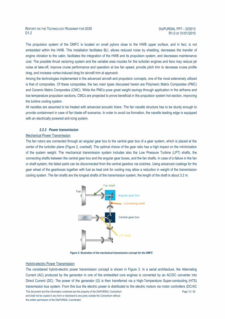
2.2.3 Power transmission
Mechanical Power Transmission
The fan rotors are connected through an angular gear box to the central gear box of a gear system, which is placed at the
center of the turbofan plane (Figure 2, overleaf). The optimal choice of the gear ratio has a high impact on the minimization
of the system weight. The mechanical transmission system includes also the Low Pressure Turbine (LPT) shafts, the
connecting shafts between the central gear box and the angular gear boxes, and the fan shafts. In case of a failure in the fan
or shaft system, the failed parts can be disconnected from the central gearbox via clutches. Using advanced coatings for the
gear wheel of the gearboxes together with fuel as heat sink for cooling may allow a reduction in weight of the transmission
cooling system. The fan shafts are the longest shafts of the transmission system, the length of the shaft is about 3.2 m.
Figure 2: Illustration of the mechanical transmission concept for the DMFC
Hybrid-electric Power Transmission
The considered hybrid-electric power transmission concept is shown in Figure 3. In a serial architecture, the Alternating
Current (AC) produced by the generator in one of the embedded core engines is converted by an AC/DC converter into
Direct Current (DC). The power of the generator (G) is then transferred via a High-Temperature Super-conducting (HTS)
transmission bus system. From this bus the electric power is distributed to the electric motors via motor controllers (DC/AC

This document and the information contained are the property of the DisPURSAL Consortium
and shall not be copied in any form or disclosed to any party outside the Consortium without
the written permission of the DisPURSAL Coordinator.
Page 13 / 42
REPORT ON THE TECHNOLOGY ROADMAP FOR 2035 D1.2
DISPURSAL FP7 – 323013 R1.0 OF 31/01/2015
inverters), finally driving the fans. In case of a failure in a sub-system, this system is disconnected from the remaining
system by Solid State Power Controllers (SSPC).
Figure 3: Illustration of the electric system architecture for the 2035+ Distributed Multiple-Fans Concept
2.2.4 Structural Requirements
A major challenge associated with the propulsion system of the DMFC is related to the requirement to provide adequate
corridors for the event of turbo machinery disk burst. By using a HWB aircraft configuration with the engines installed at the
rear part of the upper surface, the damage potential due to Foreign Object Damage (FOD) is greatly reduced, yet
appropriate reinforcement of the nacelle and body structure and careful placing of critical systems is necessary to prevent
critical damage in case of disc burst events.
2.2.5 Thermal Management and Cooling
Similar to conventional turbofan engines, all engines as well as the fuel cell APU were assumed to be equipped with a fire
extinguishing system.
2.2.6 Multi-functional and Operational Aspects
One of the challenges associated with BLI is rooted in the requirement of providing a clean and uniform inflow field into the
fans in order to yield maximum viscous drag ingestion. The coupling effects, namely, airframe / inlet / fan / Fan Exit Guide
Vane (FEGV), will play a key role in BLI propulsion design. For the DMFC, flow straightening may be provide by special
shaping of the upper surface upstream of the propulsion system intake or guide vanes in a similar way as proposed for the
Fuselage Fan (see Section 3.2.7) to create a more uniform flow at the fan face, and thereby avoiding potential performance
degradation.
2.2.7 “Retro-fit” Capabilities for Hybrid-Electric Variant
In the case of a retro-fit with a hybrid-electric power-train, the fan/ core-engine arrangement has to be adapted accordingly.
The center turbofan engine would be replaced by an electrically driven fan, and gas turbines plus generators would be
integrated by being partially submerged within the upper body structure. Effort and complexity for a retro-fit could be reduced
significantly if respective provisions and structural preparations are already included in the structure of the baseline design.
Next to structural adaptations, weight and balance characteristics have to be re-evaluated given the large lever arm of the
propulsion system elements relative to the aircraft center of gravity. In addition, the changes to the Maximum Take-Off

This document and the information contained are the property of the DisPURSAL Consortium
and shall not be copied in any form or disclosed to any party outside the Consortium without
the written permission of the DisPURSAL Coordinator.
Page 14 / 42
REPORT ON THE TECHNOLOGY ROADMAP FOR 2035 D1.2
DISPURSAL FP7 – 323013 R1.0 OF 31/01/2015
Weight (MTOW) should be within reasonable limits without the necessity to reinforce major aircraft structures such as the
wing or the landing gear.
2.3 State of the Art and Gaps in Technology
This section classifies the required systems and technologies for the DMFC as outlined in the previous section according to
the present-day TRL scale. In addition, development steps are defined to bring each technology up to TRL 6 (technology
freeze ready for product development activities).
2.3.1 Hybrid Wing-Body Morphology
- Airframe: TRL 3
o Main structures made from CFRP structure: TRL 6
o Aerodynamic design and performance assessment: TRL 3-4
o Structural design and performance assessment: TRL3
o Riblets: TRL 3
Required technology steps: The design of the HWB configuration with high-fidelity tools such as RANS codes
(12) for aerodynamic performance assessment can be considered reaching a TRL 4 for cruise conditions. In
low speed conditions for high-lift configurations or at the limits of the high speed flight domain (buffet
conditions) it can be stated that a TRL 3 is reached with such tools. In addition, it can be noticed that a
complete assessment of aerodynamic performance can only be done with computations of the whole 3D
configuration including the engines. A higher TRL can be obtained with more advanced tools (URANS or LES
codes). Specific post-processing codes can also be used for an accurate evaluation of the aerodynamic
performance (13). The TRL can also be increased by execution of wind-tunnel tests, allowing for a TRL
around 5. Higher values of TRL can be reached through flight tests. A reduction of the viscous drag of the
HWB can be obtained by the installation of riblets on its skin. Although aerodynamic flight tests have already
been performed, manufacturing and operational in-flight concerns limit this technology to a TRL 3. Activities
on materials and aerodynamic wind-tunnel or flight tests can lead to a higher TRL value. An acceptable flight
mechanics behavior can be a prohibitive constraint for the HWB. An accurate aerodynamic design can be
obtained with high fidelity numerical tools taking into account the movable surfaces. The confidence in the
results can be improved with wind-tunnel tests or flight tests. For the design of the HWB structure, the use of
high-fidelity software, such as NASTRAN (14), allows to reach at least TRL 3. Ground tests with application of
static or dynamic loads would lead to higher TRLs.
2.3.2 Core Engine Technology
- Center Turbofan and Connected Fans : TRL 5
o Geared Turbofan (GTF) technology in principle demonstrated in relevant operating environment (15),
needs to be proven for considered thrust class and specific thrust level (includes in particular increased
power transmission and increased gear ratio of the fan drive gear system). See EC FP7 projects related
to advanced gas turbine propulsion systems LEMCOTEC (16), E-BREAK (17) and ENOVAL (18). More
efficient engine cores, especially when highly loaded with additional power off-take, require an increased
Overall Pressure Ratio (OPR) and increased Turbine-Entry Temperatures (TET). The combustion
chamber should feature a correspondingly advanced design in order to compensate the detrimental
This document and the information contained are the property of the DisPURSAL Consortium
and shall not be copied in any form or disclosed to any party outside the Consortium without
the written permission of the DisPURSAL Coordinator.
Page 15 / 42
REPORT ON THE TECHNOLOGY ROADMAP FOR 2035 D1.2
DISPURSAL FP7 – 323013 R1.0 OF 31/01/2015
effects resulting from increased compressor exit temperatures and pressures with respect to NOx-
emissions.
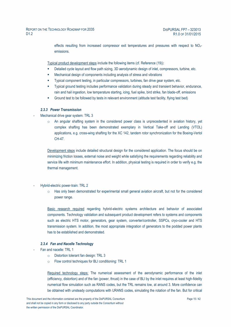
Typical product development steps include the following items (cf. Reference (19)):
Detailed cycle layout and flow path sizing, 3D aerodynamic design of inlet, compressors, turbine, etc.
Mechanical design of components including analysis of stress and vibrations
Typical component testing, in particular compressors, turbines, fan drive gear system, etc.
Typical ground testing includes performance validation during steady and transient behavior, endurance,
rain and hail ingestion, low temperature starting, icing, fuel spike, bird strike, fan blade-off, emissions
Ground test to be followed by tests in relevant environment (altitude test facility, flying test bed)
2.3.3 Power Transmission
- Mechanical drive gear system: TRL 3
o An angular shafting system in the considered power class is unprecedented in aviation history, yet
complex shafting has been demonstrated exemplary in Vertical Take-off and Landing (VTOL)
applications, e.g. cross-wing shafting for the XC 142, tandem rotor synchronization for the Boeing-Vertol
CH-47.
Development steps include detailed structural design for the considered application. The focus should be on
minimizing friction losses, external noise and weight while satisfying the requirements regarding reliability and
service life with minimum maintenance effort. In addition, physical testing is required in order to verify e.g. the
thermal management.
- Hybrid-electric power-train: TRL 2
o Has only been demonstrated for experimental small general aviation aircraft, but not for the considered
power range.
Basic research required regarding hybrid-electric systems architecture and behavior of associated
components. Technology validation and subsequent product development refers to systems and components
such as electric HTS motor, generators, gear system, converter/controller, SSPCs, cryo-cooler and HTS
transmission system. In addition, the most appropriate integration of generators to the podded power plants
has to be established and demonstrated.
2.3.4 Fan and Nacelle Technology
- Fan and nacelle: TRL 1
o Distortion tolerant fan design: TRL 3
o Flow control techniques for BLI conditioning: TRL 1
Required technology steps: The numerical assessment of the aerodynamic performance of the inlet
(efficiency, distortion) and of the fan (power, thrust) in the case of BLI by the inlet requires at least high-fidelity
numerical flow simulation such as RANS codes, but the TRL remains low, at around 3. More confidence can
be obtained with unsteady computations with URANS codes, simulating the rotation of the fan. But for critical

This document and the information contained are the property of the DisPURSAL Consortium
and shall not be copied in any form or disclosed to any party outside the Consortium without
the written permission of the DisPURSAL Coordinator.
Page 16 / 42
REPORT ON THE TECHNOLOGY ROADMAP FOR 2035 D1.2
DISPURSAL FP7 – 323013 R1.0 OF 31/01/2015
operating conditions with boundary layer separations in the inlet, fully unsteady codes must be used. Higher
TRL values can be obtained with wind-tunnel tests of the configuration, the model being equipped with a
balance for force measurements and with unsteady measurement probes, in particular in the fan plane.
Structural computations of the fan blades in the distorted flow-field are required to guarantee structural
integrity.
The decrease of distortion or a better distribution along the azimuth direction can be obtained with the
introduction of flow control techniques (20). These techniques can be passive (vortex generators) or active
(jets). The numerical investigation of their effects can be done with RANS codes featuring specific boundary
conditions or with a direct computation of these devices. Wind-tunnel tests can also be performed to support
the improvement assessment with these techniques.
- Thrust vectoring system and variable area nozzle technologies: TRL 4-5
o The technologies are used on in-production military engines, needs to be proven for considered features
of civil application (certification, arrangement, integration in distributed propulsion, etc.).
- Acoustic liners: TRL 4-5
o Advanced acoustic liners for turbofan engines and fans are available in present engines, the technology
needs to be adapted to the considered application. Also, the wing leading edge and landing gear
acoustic treatment should be considered.
2.3.5 Thermal Management and Cooling
- Fire extinguishing system for the turbofan engines are available in present engines, no specific adaptation
necessary: TRL 6
- Thermal management of Mechanical drive gear system: TRL 4
2.3.6 Multi-functional and Operational Aspects
- Multi-functional and Operational Aspects: TRL 3-4
o Technologies providing coupling effects of airframe / inlet / fan / FEGV
Required technology steps: Technologies providing minimal distortion of inflow field into the fans in order to
yield maximum viscous drag ingestion are currently under investigation. Possible scaled and full-scale
experiments are required to advance the maturity up to TRL 6.
2.4 Research and Technology Roadmap (time axis)
The technology related aspects outlined above are presented in Figure 4 in the form of a technology roadmap chart
(overleaf). Here, an estimation of the required time for technology research (TRL 1 to 4) and technology validation (TRL 4 to
6) as well as subsequent product development is provided within the time frame from 2015 to 2035. For product
development, a typical time period of five years from technology freeze in year 2030 to EIS in 2035 was assumed.

This document and the information contained are the property of the DisPURSAL Consortium
and shall not be copied in any form or disclosed to any party outside the Consortium without
the written permission of the DisPURSAL Coordinator.
Page 17 / 42
REPORT ON THE TECHNOLOGY ROADMAP FOR 2035 D1.2
DISPURSAL FP7 – 323013 R1.0 OF 31/01/2015
Figure 4 Technology Roadmap Chart for Distributed Multiple-Fans Concept
Num
eric
al T
ools
W
ind-
tunn
el T
ests
Gro
und
Tes
ts
Num
eric
al T
ools
W
ind-
tunn
el T
ests
Gro
und
Tes
ts
Fly
ing
Tes
t Bed
2015
2035
2025
2020
2030
DM
FC
Pro
puls
ion
Sys
tem
Airc
raft
Cer
tific
atio
n
Technology Research (TRL 1-4)
Technology Validation (TRL 4-6)
DM
FC
Pro
puls
ion
Sys
tem
DM
FC
aer
odyn
amic
and
str
uctu
ral i
nteg
ratio
n
DM
FC
PP
S a
erod
ynam
ic a
nd
stru
ctur
al in
tegr
atio
n
Mec
h. P
ower
Tra
nsm
issi
on
Mec
h. P
ower
Tra
nsm
issi
on
Hyb
rid-e
lect
ric P
ower
Tra
nsm
issi
on
Hyb
rid-e
lect
ric P
ower
Tra
nsm
issi
on
Hyb
rid-e
lect
ric P
ower
Tra
nsm
issi
on
Mul
ti-fu
nctio
nal A
spec
ts
Mul
ti-fu
nctio
nal A
spec
ts
Ann
exed
Tec
hnol
ogie
s
Ann
exed
Tec
hnol
ogie
s
Det
aile
d D
esig
n of
Airc
raft
Sys
tem
s
Ove
rall
Airc
raft
Des
ign
Product Development (incl.Testing)
DM
FC
Pro
puls
ion
Sys
tem
Mec
h. P
ower
Tra
nsm
issi
on
Prin
cipl
e of
BLI
/ W
ake
Fill
ing
Prin
cipl
e of
BLI
/ W
ake
Fill
ing
The
rmal
Man
gmt. The
rmal
Man
gmt.
TR
L 6
Technology Readiness Level (TRL)
TR
L 4
DM
FC
aer
odyn
amic
and
str
uctu
ral i
nteg
ratio
n
Mul
ti-fu
ntio
nalA
spec
ts
Tec
hn
olo
gy
Fre
eze
EIS
Pro
toty
pe

This document and the information contained are the property of the DisPURSAL Consortium
and shall not be copied in any form or disclosed to any party outside the Consortium without
the written permission of the DisPURSAL Coordinator.
Page 18 / 42
REPORT ON THE TECHNOLOGY ROADMAP FOR 2035 D1.2
DISPURSAL FP7 – 323013 R1.0 OF 31/01/2015
this page is intentionally blank
This document and the information contained are the property of the DisPURSAL Consortium
and shall not be copied in any form or disclosed to any party outside the Consortium without
the written permission of the DisPURSAL Coordinator.
Page 19 / 42
REPORT ON THE TECHNOLOGY ROADMAP FOR 2035 D1.2
DISPURSAL FP7 – 323013 R1.0 OF 31/01/2015
3. Roadmap for Propulsive Fuselage Technology
This section initially describes the general layout of the PFC. This includes a short discussion of the underlying physical
principles as well as a synopsis of key results found during the conceptual investigation conducted in the DisPURSAL WP3.
More details about the conceptualization and a comprehensive summary of sizing and performance results can be found in
Deliverable D3.2 (2). Section 3.2 provides a detailed description of technology features and key systems associated with the
PFC, while Section 3.3 contains a present-day classification of the required systems and technologies as well as a definition
of development steps for the individual systems and technologies to reach TRL 6. As a result of the selected EIS year 2035,
technology freeze was set as year 2030.
3.1 The Propulsive Fuselage Concept Layout
Particular aircraft-level benefits are expected from the prospect of distributing the production of thrust along main
components of the airframe, i.e. distributed propulsion (3). As described in DisPURSAL D3.1 (21), a most promising concept
for distributed propulsion is the PFC, which has been investigated as part of the DisPURSAL project.
The main purpose of the fuselage installed propulsor is the ingestion of the fuselage boundary layer and the distribution of
thrust along the viscous wake generated by the fuselage. Through locally filling the momentum deficit caused by the
boundary layer flow on the fuselage surface using the nozzle jet of the Fuselage Fan (FF) propulsion system, the fuselage
zero-lift drag, and therefore the total required propulsive power can be reduced relative to a conventional aircraft
configuration (7), (8).
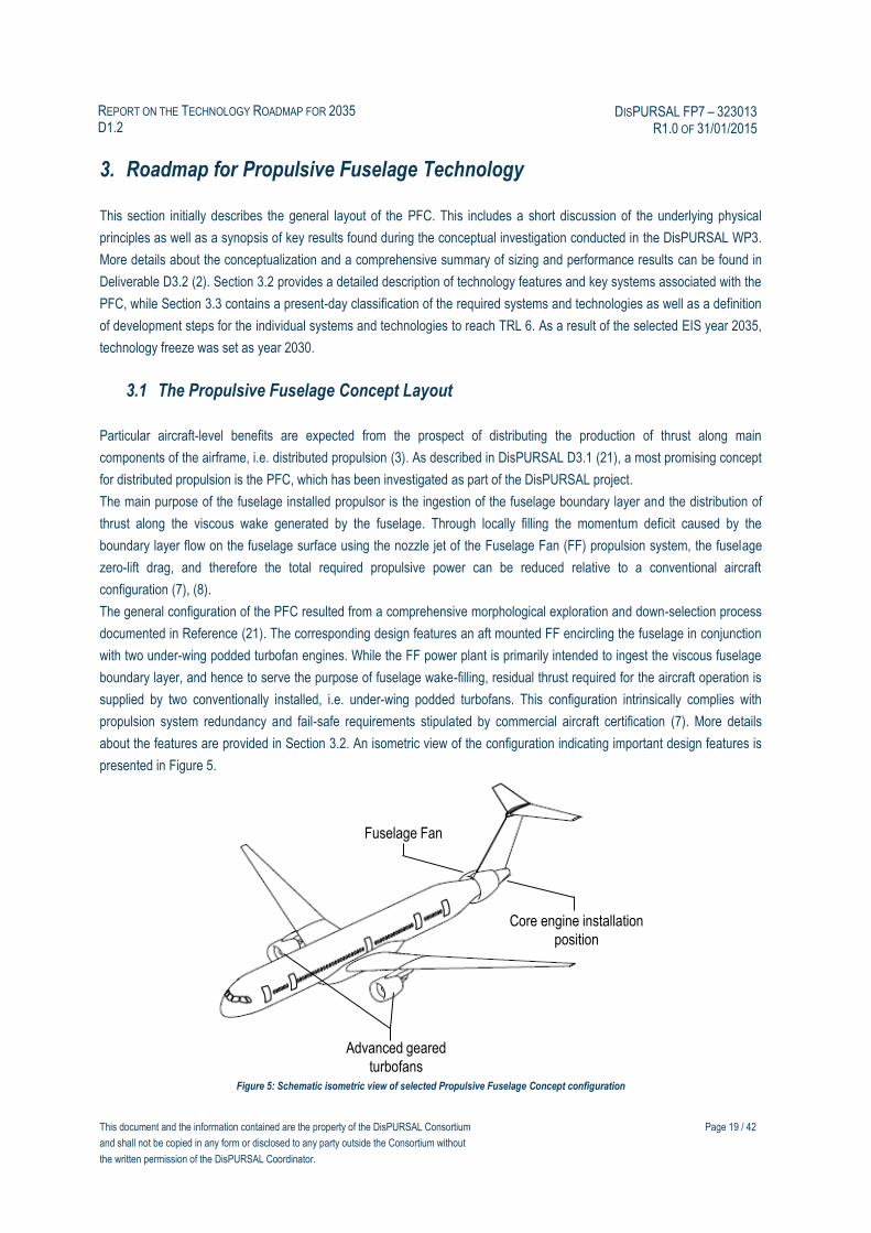
The general configuration of the PFC resulted from a comprehensive morphological exploration and down-selection process
documented in Reference (21). The corresponding design features an aft mounted FF encircling the fuselage in conjunction
with two under-wing podded turbofan engines. While the FF power plant is primarily intended to ingest the viscous fuselage
boundary layer, and hence to serve the purpose of fuselage wake-filling, residual thrust required for the aircraft operation is
supplied by two conventionally installed, i.e. under-wing podded turbofans. This configuration intrinsically complies with
propulsion system redundancy and fail-safe requirements stipulated by commercial aircraft certification (7). More details
about the features are provided in Section 3.2. An isometric view of the configuration indicating important design features is
presented in Figure 5.
Figure 5: Schematic isometric view of selected Propulsive Fuselage Concept configuration
Fuselage Fan
Core engine installation
position
Advanced geared
turbofans
This document and the information contained are the property of the DisPURSAL Consortium
and shall not be copied in any form or disclosed to any party outside the Consortium without
the written permission of the DisPURSAL Coordinator.
Page 20 / 42
REPORT ON THE TECHNOLOGY ROADMAP FOR 2035 D1.2
DISPURSAL FP7 – 323013 R1.0 OF 31/01/2015
The PFC design described in Reference (2) exhibits a block fuel burn benefit relative to the 2035R of 9.2% and 14.1%
depending upon the typical cruise speed, M0.80 and M0.78 respectively, assumed for sizing the aircraft. The design is
characterized by an intake duct height of the FF propulsion system of 0.575 m yielding close to minimum block fuel burn,
while enhancing operational robustness at high angles-of-attack. As a consequence of the increased weight due to the third
power plant, a slightly increased fuselage length as well as vehicular cascade effects such as increased wing size, the OEW
was penalized by 5.8% for the M0.80 speed sized version. This translated into an increased MTOW of 1.3%. In an initial
design robustness investigation, a considered best case scenario showed up to 11% design fuel reduction for the PFC, while
for the worst case scenario still 5.2% fuel benefit could be secured relative to the 2035R.
As a further approach regarding the exploration of the PFC, a hybrid-electric PFC was investigated in addition to the gas
turbine based FF drive. Here, the required electrical power to drive the FF was assumed to be extracted from the underwing
podded power plants, which therefore yielded an increased size relative to the turbo engine based PFC. The additional
weight of the electrical power train propagated into a more severe OEW increase compared to the gas turbine based PFC
(+16.3%). The identified design features a block fuel reduction of 7.3% relative to the 2035R, while MTOW was predicted to
increase by 8.0%.
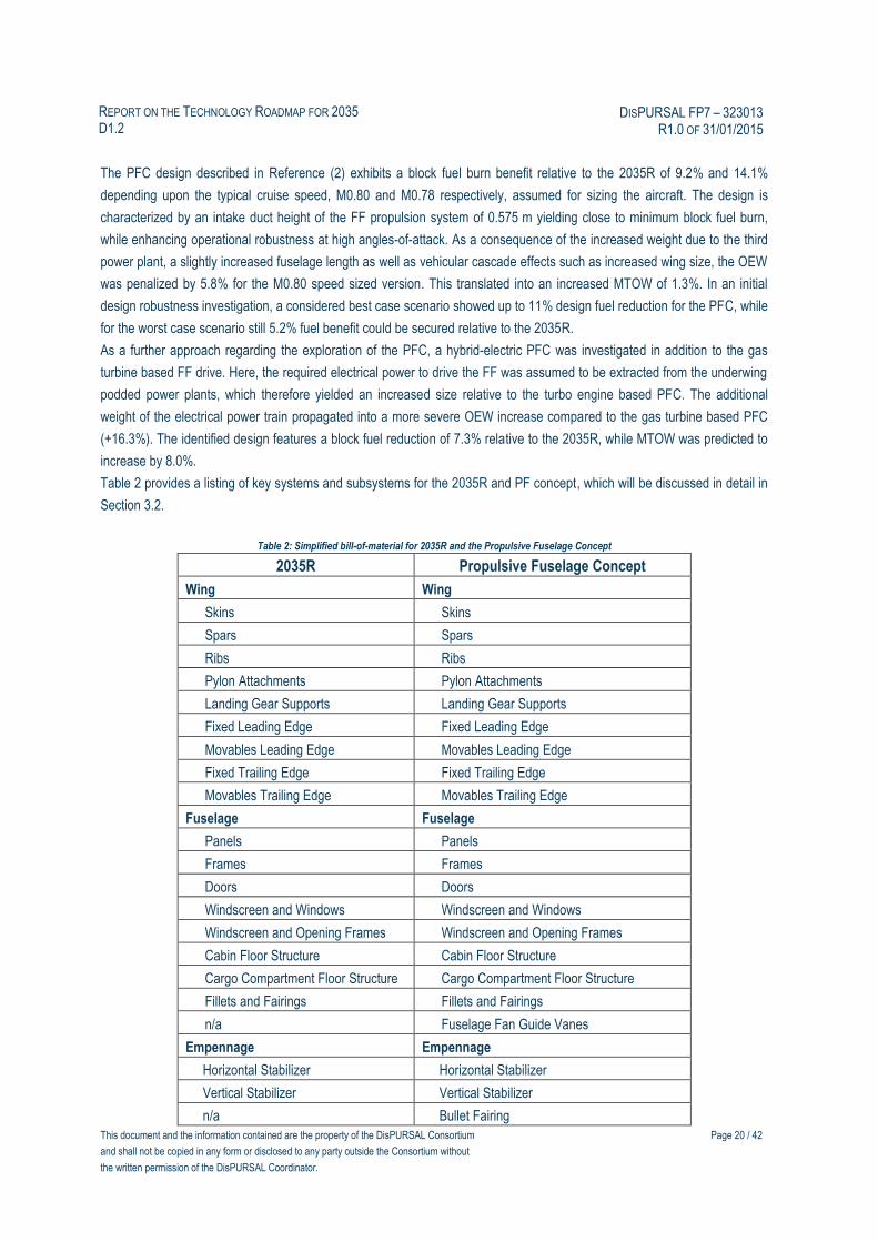
Table 2 provides a listing of key systems and subsystems for the 2035R and PF concept, which will be discussed in detail in
Section 3.2.
Table 2: Simplified bill-of-material for 2035R and the Propulsive Fuselage Concept
2035R Propulsive Fuselage Concept
Wing Wing
Skins Skins
Spars Spars
Ribs Ribs
Pylon Attachments Pylon Attachments
Landing Gear Supports Landing Gear Supports
Fixed Leading Edge Fixed Leading Edge
Movables Leading Edge Movables Leading Edge
Fixed Trailing Edge Fixed Trailing Edge
Movables Trailing Edge Movables Trailing Edge
Fuselage Fuselage
Panels Panels
Frames Frames
Doors Doors
Windscreen and Windows Windscreen and Windows
Windscreen and Opening Frames Windscreen and Opening Frames
Cabin Floor Structure Cabin Floor Structure
Cargo Compartment Floor Structure Cargo Compartment Floor Structure
Fillets and Fairings Fillets and Fairings
n/a Fuselage Fan Guide Vanes
Empennage Empennage
Horizontal Stabilizer Horizontal Stabilizer
Vertical Stabilizer Vertical Stabilizer
n/a Bullet Fairing

This document and the information contained are the property of the DisPURSAL Consortium
and shall not be copied in any form or disclosed to any party outside the Consortium without
the written permission of the DisPURSAL Coordinator.
Page 21 / 42
REPORT ON THE TECHNOLOGY ROADMAP FOR 2035 D1.2
DISPURSAL FP7 – 323013 R1.0 OF 31/01/2015
2035R Propulsive Fuselage Concept
Landing Gear Landing Gear
MLG MLG
NLG NLG
Pylons Pylons
Underwing Podded Engines Underwing Podded Engines
Dry Engines Dry Engines
Nacelle (incl. thrust reverser) Nacelle (incl. thrust reverser)
n/a
Fuselage Fan Engine
Fuselage Fan assembly
Nacelle
Thrust reverser / spoiler system
Core engine
S-duct intake
Fuselage Fan Gear System incl. drive shafts
Support structures
Fuel System Fuel System
APU Fuel Cell System APU Fuel Cell System
Environmental Control System Environmental Control System
Flight Controls Flight Controls
Electrical System Electrical System
Fire Protection Fire Protection
Podded engines Podded engines
n/a Fuselage Fan engine
Instruments Instruments
Automatic Flight System Automatic Flight System
Navigation and Communication Navigation and Communication
Lighting Lighting
Furnishings Furnishings
Operational Items Operational Items
3.2 Technology Requirements
The following section discusses the required technologies for a number of key systems and components associated with the
PFC. Additional information can be found in Reference (2).
3.2.1 Aircraft Morphology and Annexed Technologies
Generally, it was assumed that the same advanced technology standard as for the 2035R aircraft applies to the PFC.
Therefore, the design of the fuselage forward and center sections is similar as for the 2035R and the aft section of the
2035R is replaced by the specific design associated with the PFC. Also, the same advanced materials for the structural
design, such as omnidirectional ply orientation of carbon fibers were assumed to be implemented. The wing features a
slender, very flexible structure allowing for an Aspect Ratio exceeding 12.0.
This document and the information contained are the property of the DisPURSAL Consortium
and shall not be copied in any form or disclosed to any party outside the Consortium without
the written permission of the DisPURSAL Coordinator.
Page 22 / 42
REPORT ON THE TECHNOLOGY ROADMAP FOR 2035 D1.2
DISPURSAL FP7 – 323013 R1.0 OF 31/01/2015
In order to maximize the viscous drag reduction effect attainable from BLI, and, to minimize losses due to shear flow on the
fuselage aft cone, the aft fuselage power plant needs to be installed as far aft as possible. For the investigated aircraft
layout, axial positioning, however, was determined by the aerodynamic and structural integration of the tail and the FF
nacelle for low interference and compressibility drag, and, the requirement to provide appropriate turbo engine disk burst
corridors not interfering with critical system elements. In order to facilitate an equal cabin standard as the 2035R described
in Reference (9), the overall fuselage length of the PFC aircraft needed to be increased by 2.0 meters, or +3% compared to
the 2035R in order to yield identical cabin accommodation capacity.
The fuselage shaping of a PFC aircraft needs to facilitate minimum in-flow distortion for the FF. Therefore, excrescences in
front of the FF have to be avoided as much as possible and fuselage body junctions to adjacent airframe components such
as the wing and landing gear require particularly careful aerodynamic design. The installed encircling propulsor stipulates a
circular aft-fuselage cross-section and zero upsweep angle. The S-shape contour of the aft fuselage towards the propulsive
device needs to be tailored to minimize flow pressure gradients and super-velocities, and, to maximize FF inflow capacity.
Nacelle outer contour and relative maximum thickness position are to be tailored to avoid super-velocities, and, to allow for a
sound approach to the aerodynamic and structural integration of the empennage. Take-off in crosswind condition must also
be considered when designing nacelle lips, as well as go-around procedures at high angle-of-attack and high thrust setting.
Those flight cases will produce fan distortion that must remain acceptable for the fan of the PFC.
Regarding the empennage, a T-tail arrangement was considered best and balanced for the PFC aircraft. A 5.0° anhedral
was selected for the horizontal tail in order to ameliorate torsional loads on the vertical tail structure during side-slip
maneuvers. Landing gear length needs to be governed by the rotation angle, and, nose gear collapse scenarios.
3.2.2 Core Engine and Turbofan Technology
For the podded power plants evolutionary advanced geared turbofan engines featuring an ultra-high bypass ratio design
(BPR~18) and a high-speed LPT were applied. Cycle parameters correspond to the targeted technology freeze year 2030.
For the FF propulsion system different basic architectures may be considered including ducted and unducted as well as
single and counter-rotating propulsive devices encircling the aft part of a cylindrical fuselage (4), (7), (8). Due to increased
external noise associated with open rotor arrangements, a ducted propulsor was selected, thus also offering significantly
increased robustness against tail strike events. A single rotating fan was preferred over multi-stage options for reasons of
substantially reducing complexity with respect to mechanical and structural integration.
The FF is driven by the LPT of a turbo-engine arranged in the aft-cone of the aircraft. A planetary reduction gear system
decouples FF and LPT rotational speeds. The core nozzle is installed at the very aft end of the symmetrically contracting
fuselage aft-cone. The FF nacelle incorporates an annular structure required for load transmission between the aft and
center fuselage sections, and, to provide containment in case of fan blade-off scenarios. Several axial struts arranged in the
FF intake serve as load transmitting structures and provide the required space for installing fuel supply lines and electric
wiring. In order to avoid ice formation, the nacelle leading edge is equipped with an electrically powered anti-icing system.
Air supply to the core engine is provided by an eccentrical swan neck intake installed downstream of the FF stator featuring
shape transformation from a smoothed rectangular shape at the inlet to a circular cross section at the attachment to the core
engine. In order to reduce pressure losses in the S-duct, the contour of the fuselage upstream the duct inlet necessitates a
symmetrical contraction yielding an increasing flow area, and hence a reduction of the axial flow Mach number. The axial
positioning of the core inlet is tailored to provide sufficient space for straightening possibly remaining non-uniformities of the
FF stator outflow.
A cutaway view of the FF propulsion system showing important components and design features is given in Figure 6
(overleaf).

This document and the information contained are the property of the DisPURSAL Consortium
and shall not be copied in any form or disclosed to any party outside the Consortium without
the written permission of the DisPURSAL Coordinator.
Page 23 / 42
REPORT ON THE TECHNOLOGY ROADMAP FOR 2035 D1.2
DISPURSAL FP7 – 323013 R1.0 OF 31/01/2015
Figure 6: Cutaway view of the Fuselage Fan propulsion system indicating important components and design features
Following a projection of the All-Electric Aircraft (AEA) design paradigm, a hydrogen fuel cell-based Auxiliary Power Unit
(APU) providing power for a continuous operation of all aircraft subsystems is fitted in the annular space between the
Fuselage Fan Drive Gear System (FFDGS) and the fuselage contour (not shown in Figure 6 above). A conical cryogenic
tank containing the required amount of liquid hydrogen is installed between the rear pressure bulkhead defining the aft of the
cabin pressure vessel and the support structure of the FF.
3.2.3 Fuselage Fan Power Transmission
Mechanical Power Transmission
The FF rotor is connected to the ring gear of a planetary gear system, which is placed at the center of the fan plane. As
depicted in Figure 7, the Low Pressure (LP) spool of the two-spool gas turbine core engine installed behind the FF is
connected to the sun gear. The planet carrier is fixed to the aircraft structure and allows only a rotation of the planet gears.
The majority of the structural and aerodynamic loads from the aft fuselage section and the empennage are transmitted
through the nacelle. Therefore, intake struts are installed upstream and downstream to the FF, while the integrated stators
and struts allow for radial load transmission downstream the rotor. The non-rotating planet carrier of the gear stage may be
considered as a secondary structural load path.
Figure 7: Illustration of mechanical transmission concept
Core Engine
Driveshaft
Planetary Gear System
Fuselage Fan Rotor
S-Duct
Ring Spar
Intake Struts
FF nacelle
intake strut
fan blade
gear box
core engine
core air intake
stator blade a/c nacelle
a/c structure

This document and the information contained are the property of the DisPURSAL Consortium
and shall not be copied in any form or disclosed to any party outside the Consortium without
the written permission of the DisPURSAL Coordinator.
Page 24 / 42
REPORT ON THE TECHNOLOGY ROADMAP FOR 2035 D1.2
DISPURSAL FP7 – 323013 R1.0 OF 31/01/2015
Hybrid-electric Power Transmission
The hybrid-electric power transmission concept (series-parallel hybrid architecture) is shown in Figure 8. AC produced by
the generators of the under-wing podded power plants is converted with the help of an AC/DC converter into DC. The power
of both generators is then transferred via HTS cables to a bus system. From this bus the combined electric power from both
generators is distributed to the FF and finally converted again from DC to AC with the help of a voltage source inverter. The
entire system is also protected by SSPCs.
Figure 8: Illustration of hybrid-electric power transmission concept
3.2.4 Fan and Nacelle Technology
Considering the advanced technology level, fan blades are assumed to be made from a material mix of 80% Carbon Fibre
Reinforced Polymers (CFRP) and 20% titanium, while the design of fan stationary parts is assumed to be based entirely on
CFRP. An intrinsic feature of the FF is the high hub-to-tip ratio of the FF rotor compared to conventional turbofan engines
yielding greatly reduced centrifugal stress values for typical rotor tip velocities compared to existing conventional fans (4).
Hence, the critical sizing cases for the rotor structure are considered to occur due to the bending and torsional loads induced
by the rotor blades.
As outlined above, apart from its aerodynamic purpose, the FF nacelle contains a load carrying structure which has to be
sturdy enough to provide containment in case of FF blade-off scenarios, and, to ensure the structural integrity of the aft
fuselage during tail strike events. As an additional safety aspect, the PF design features a tail-skid mounted on the
underside of the FF nacelle to prevent damage to the propulsive device during tail-scrape events.
3.2.5 Structural Requirements
A major challenge associated with the PFC is related to the transmission of loads across the FF plane as the load path
between the aft and center section of the fuselage is disrupted by the FF rotor. Mechanical loads introduced at the aft-end of
the fuselage include inertial and tail plane aerodynamic as well as gyroscopic loads. The axial positioning of the FF
propulsion system relative to other basic aircraft component groups was conducted in accordance with typical design
standards applicable to commercial transport aircraft. This is mainly driven by the requirement to provide adequate corridors
for the event of turbo-machinery disk burst. The hydrogen tank and the APU, as well as the pressurized part of the cabin are
placed well outside the recommended fragment spread angle of ±15° applicable to fan disk burst scenarios (22). Also,
critical primary/secondary flight control functions such as rudder, elevator and horizontal stabilizer trim actuators are
Motor Bus System
ACDC
GPU
.
Subsystems
SSPC
DCAC
DCAC
GCU GCU
G #1 G #2
SS
PC
SS
PC
SS
PC
SS
PC
Motor Bus System
ACDC
GPU
.
SS
PC
SS
PC
SS
PC
Subsystems
SSPC
DCAC
SS
PC
DCAC
GCU GCU
G #1 G #2
DCDC
SS
PC
Energy
Storage
System
Motor Bus System
ACDC
GPU
.
SS
PC
SS
PC
SS
PC
Subsystems
SSPC
DCAC
SS
PC
DCAC
GCU GCU
G #1 G #3
DCAC
SS
PC
GCU
G #2
Motor Bus System
ACDC
GPU
.
SS
PC
SS
PC
SS
PC
Subsystems
SSPC
DCAC
SS
PC
DCAC
GCU GCU
G #1 G #3
DCAC
SS
PC
GCU
G #2
ACDC
SS
PC
ACDC
SS
PC
Motor Bus System
ACDC
GPU
.
SS
PC
SS
PC
SS
PC
Subsystems
SSPC
DCAC
SS
PC
DCAC
GCU GCU
G #1 G #2
DCDC
SS
PC
Energy
Storage
System
High Power Subsystem Bus
GPU
.
SS
PC
SS
PC
Low
Subsystems
SSPC
DCAC
SS
PC
DCAC
GCU GCU
G #1 G #2
Motor Bus System
ACDC
SS
PC
DCAC
SS
PC
GCU
G #3
SSPC
High Power Subsystem Bus
GPU
.
SS
PC
SS
PC
Low
Subsystems
SSPC
DCAC
SS
PC
DCAC
GCU GCU
G #1 G #2
Motor Bus System
ACDC
SS
PC
DCDC
SS
PC
SSPC
Electrical
Energy Storage
and Power
System
Concept 1 Concept 2
Concept 3 Concept 4
Concept 5
X
X
X
X
Final Concept

This document and the information contained are the property of the DisPURSAL Consortium
and shall not be copied in any form or disclosed to any party outside the Consortium without
the written permission of the DisPURSAL Coordinator.
Page 25 / 42
REPORT ON THE TECHNOLOGY ROADMAP FOR 2035 D1.2
DISPURSAL FP7 – 323013 R1.0 OF 31/01/2015
positioned outside a ±5° angle measured from the last LPT rotor plane. Due to the fuel cell based APU system no rotor
burst of the APU can occur.
3.2.6 Thermal Management and Cooling
The core engine is assumed to be treated with heat shielding and noise suppressing insulation. Similar to conventional
turbofans, the FF core engine as well as fuel cell APU were assumed to be equipped with a fire extinguishing system.
3.2.7 Multi-functional and Operational Aspects
One of the challenges associated with the PFC is rooted in the requirement of providing a clean inflow field into the FF in
order to yield maximum viscous drag ingestion. Flow straightening devices (Fuselage Fan Guide Vanes, FFGV) installed on
the fuselage surface in front on the FF may help to create a uniform flow as it enters the FF inlet, thereby avoiding potential
performance degradation. Depending on the flight condition a rotating mechanism may adjust the angle-of-attack of each
vane. The FFGVs should feature electric heating in order to avoid potential ice accretion problems. A conceptual sketch of
the FFGV is given in Figure 9.
Figure 9: Schematic view of Fuselage Fan Guide Vanes
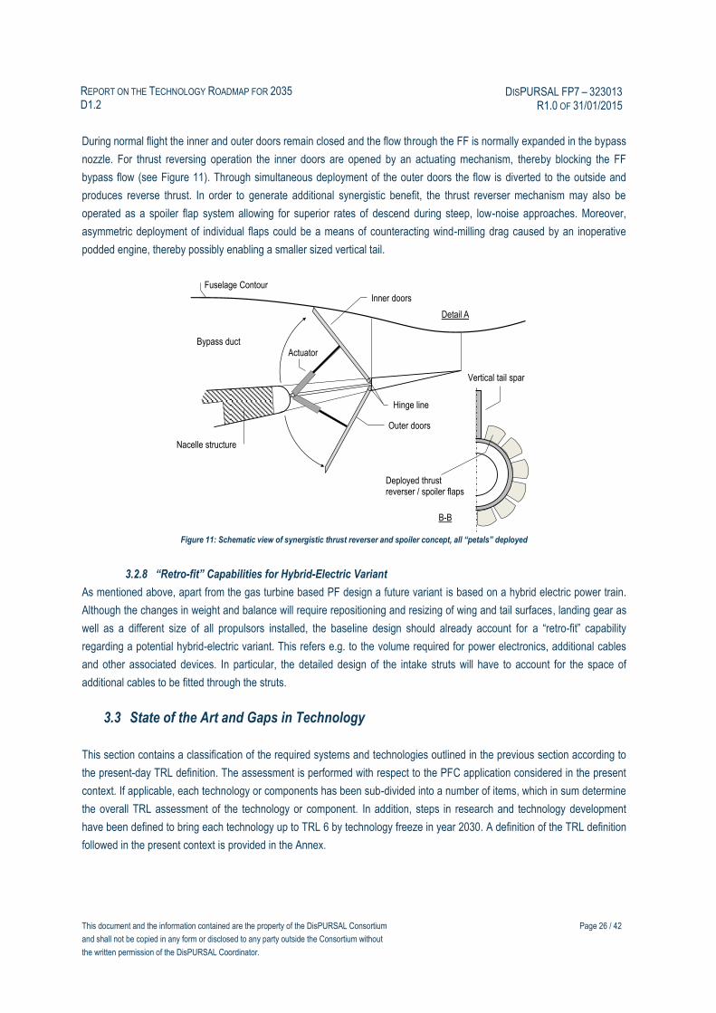
As an additional approach to a synergistic FF power plant integration, a thrust reversing concept for the aft installed
propulsion system was conceptually defined. Based on the investigation described in Reference (23), the concept comprises
an array of circumferentially distributed doors installed in the aft part of the FF nacelle between the load carrying structure
and the nacelle trailing edge (see Figure 10, overleaf), which can be opened both to the outside and towards the bypass
duct.
Figure 10: Schematic view of synergistic thrust reverser and spoiler concept, all “petals” deployed
x
z
Detail A
B
B
This document and the information contained are the property of the DisPURSAL Consortium
and shall not be copied in any form or disclosed to any party outside the Consortium without
the written permission of the DisPURSAL Coordinator.
Page 26 / 42
REPORT ON THE TECHNOLOGY ROADMAP FOR 2035 D1.2
DISPURSAL FP7 – 323013 R1.0 OF 31/01/2015
During normal flight the inner and outer doors remain closed and the flow through the FF is normally expanded in the bypass
nozzle. For thrust reversing operation the inner doors are opened by an actuating mechanism, thereby blocking the FF
bypass flow (see Figure 11). Through simultaneous deployment of the outer doors the flow is diverted to the outside and
produces reverse thrust. In order to generate additional synergistic benefit, the thrust reverser mechanism may also be
operated as a spoiler flap system allowing for superior rates of descend during steep, low-noise approaches. Moreover,
asymmetric deployment of individual flaps could be a means of counteracting wind-milling drag caused by an inoperative
podded engine, thereby possibly enabling a smaller sized vertical tail.
Figure 11: Schematic view of synergistic thrust reverser and spoiler concept, all “petals” deployed
3.2.8 “Retro-fit” Capabilities for Hybrid-Electric Variant
As mentioned above, apart from the gas turbine based PF design a future variant is based on a hybrid electric power train.
Although the changes in weight and balance will require repositioning and resizing of wing and tail surfaces, landing gear as
well as a different size of all propulsors installed, the baseline design should already account for a “retro-fit” capability
regarding a potential hybrid-electric variant. This refers e.g. to the volume required for power electronics, additional cables
and other associated devices. In particular, the detailed design of the intake struts will have to account for the space of
additional cables to be fitted through the struts.
3.3 State of the Art and Gaps in Technology
This section contains a classification of the required systems and technologies outlined in the previous section according to
the present-day TRL definition. The assessment is performed with respect to the PFC application considered in the present
context. If applicable, each technology or components has been sub-divided into a number of items, which in sum determine
the overall TRL assessment of the technology or component. In addition, steps in research and technology development
have been defined to bring each technology up to TRL 6 by technology freeze in year 2030. A definition of the TRL definition
followed in the present context is provided in the Annex.
Detail A
Inner doors
Actuator
Vertical tail spar
Outer doors
Hinge line
Fuselage Contour
Nacelle structure
Bypass duct
Deployed thrust reverser / spoiler flaps
B-B

This document and the information contained are the property of the DisPURSAL Consortium
and shall not be copied in any form or disclosed to any party outside the Consortium without
the written permission of the DisPURSAL Coordinator.
Page 27 / 42
REPORT ON THE TECHNOLOGY ROADMAP FOR 2035 D1.2
DISPURSAL FP7 – 323013 R1.0 OF 31/01/2015
3.3.1 Aircraft Morphology and Annexed Technologies
- Wing: TRL 2
o Wing made from CFRP structure: TRL 6
o Slender, very flexible structure, high Aspect Ratio design: TRL 6
o Omni-directional ply orientation of carbon fibers: TRL 3 (24)
o Advanced bonding techniques: TRL 6 (25), (26)
o Shock contour bump: TRL 4 (27)
o High-lift devices must be designed so as to limit the flow downwash incoming in the PFC for low-speed
conditions: no inner flap, inner flap with low wing loading. This triggers wing stall on the mid-wing, which
may create non-symmetric stall if not designed carefully: TRL 2.
Required technology steps include the feasibility demonstration of the above outlined annexed technologies for the PF
application. A description of the annexed technologies is given in Reference (21). Product development includes
aerodynamic and aero-structural design, typical tests include e.g. ultimate-load wing bending test.
- Fuselage: TRL 2
o Smooth surface without excrescences required in order to maximize the viscous drag reduction effect
attainable from BLI: TRL 5
o Fuselage body junctions to adjacent airframe components such as the wing and landing gear require
particularly careful aerodynamic design: TRL 2
o MLGs have to be placed as far as possible from the fuselage centerline, and the nose landing gear may
be designed with an aerodynamic fairing in order to minimize flow distortion: TRL 3.
o Fuselage made from CFRP structure: TRL 6
o Omni-directional ply orientation of carbon fibers: TRL 3 (24)
o Advanced bonding techniques: TRL 6 (25), (26)
o Riblets: TRL 5-6 (28), (29), (30)
Required technology steps include integrated structural design analyses including topological optimization in order to adopt
the best load-path outcome particularly in the aft-fuselage. This also allows for a more precise determination of the forces
and moments acting on the aft-fuselage arrangement (including the empennage) during critical maneuvers. The design
needs to take into account inertial, aerodynamic and gyroscopic loads during all critical cases.
- Empennage integration: TRL 6
o The Vertical Tailplane (VTP)-nacelle intersection must be designed properly. On conventional aircraft,
the fuselage is locally shaped to accommodate the VTP, which is more difficult on the PFC as the
nacelle must comply with its own role to feed the engine with a good flow quality, e.g at take-off and go-
around operations.
- Overall aircraft aspects: TRL 3
o Overall cruise performance needs to be validated, e.g. through detailed 3D CFD analysis, and sub-scale
powered wind-tunnel testing. An unpowered test will not provide any overall benefit on a BLI
configuration: TRL 4

This document and the information contained are the property of the DisPURSAL Consortium
and shall not be copied in any form or disclosed to any party outside the Consortium without
the written permission of the DisPURSAL Coordinator.
Page 28 / 42
REPORT ON THE TECHNOLOGY ROADMAP FOR 2035 D1.2
DISPURSAL FP7 – 323013 R1.0 OF 31/01/2015
o Overall aero-propulsive performance can only be achieved with “power balance” [Reference (31)] or
“exergy balance” methods [Reference (32)], that has to be validated in transonic conditions: TRL 3.
o Overall flight domain needs to be explored with CFD but validated with wind-tunnel testing due to the
complexity of flight cases such as “impact of PFC failure on the empennage aerodynamic efficiency”,
“achievable thrust on PFC in crosswind with a wing engine failure”, “asymmetric flap failure”, etc.:TRL 3
Required technology steps include validation of overall performance, e.g. through subscale wind tunnel testing, 3D CFD
analysis, and small scale flight demonstrators.
3.3.2 Core Engine and Turbofan Technology
- Underwing podded engines (bare engine and nacelle): TRL 5
o Geared Turbofan (GTF) technology in principle demonstrated in relevant operating environment (15),
needs to be proven for considered thrust class and specific thrust level (includes in particular increased
power transmission and increased gear ratio of the fan drive gear system). See EC FP7 projects related
to advanced gas turbine propulsion systems LEMCOTEC (16), E-BREAK (17) and ENOVAL (18). The
combustion chamber should feature a correspondingly advanced design in order to compensate the
detrimental effects resulting from increased compressor exit temperatures and pressures with respect to
NOx-emissions.
Typical product development steps include the following items [cf. Reference (19)]:
Detailed cycle layout and flow path sizing, 3D aerodynamic design of inlet, compressors, turbine, etc.
Mechanical design of components including analysis of stress and vibrations
Typical component testing, in particular compressors, turbines, fan drive gear system, etc.
Typical ground testing includes performance validation during steady and transient behavior, endurance,
rain and hail ingestion, low temperature starting, icing, fuel spike, bird strike, fan blade-off, emissions
Ground test to be followed by tests in relevant environment (altitude test facility, flying test bed)
- Fuselage Fan propulsion system: TRL 2
o FF core engine: TRL 5
- Technology in principle demonstrated in relevant operating environment
Development steps for present application similar to under-wing podded engines, see above.
o S-duct: TRL 5
- S-duct intakes in service with various military and turboprop applications
Development steps require adaptation to considered application using 3D aero and structural design for minimum pressure
losses and appropriate structural integrity. The aerodynamic and mechanical characteristics should be validated through
experimental testing.
o Power Transmission see Section 3.3.3
o FF and Nacelle see Section 3.3.4
o Principle of fuselage Wake Filling: TRL 3
This document and the information contained are the property of the DisPURSAL Consortium
and shall not be copied in any form or disclosed to any party outside the Consortium without
the written permission of the DisPURSAL Coordinator.
Page 29 / 42
REPORT ON THE TECHNOLOGY ROADMAP FOR 2035 D1.2
DISPURSAL FP7 – 323013 R1.0 OF 31/01/2015
- Application of fuselage Wake Filling not existing today for transport category wide-body
aircraft, however, has been demonstrated for smaller aircraft
Research and technology steps are closely connected to FF technology (Section 3.3.4) and include experimental validation,
e.g. through wind-tunnel testing.
3.3.3 Fuselage Fan Power Transmission
- Fuselage Fan Drive Gear System: TRL 4
o Planetary reduction gear system has been demonstrated for geared turbofan application (15)
Development steps include detailed structural design for the considered FF propulsion system application. The focus should
be on minimizing friction losses, external noise and weight while satisfying the requirements regarding reliability and service
life with minimum maintenance effort. In addition, physical testing is required in order to verify e.g. the thermal management.
- Fuselage Fan shaft system (incl. bearing system): TRL 2
o As opposed to geared power plants in service, the low pressure spool of the FF core engine features a
particularly long axial dimension.
Development steps include careful mechanical design and positioning of the shaft, bearings and associated support
structures in order to avoid excessive bending modes and undesirable vibrations. An eccentricity monitoring system may be
required to ensure that transversal motions of the shaft stay within limits.
- Hybrid-electric power train: TRL 2
o Has only been demonstrated for experimental small general aviation aircraft, but not for the considered
power range.
Basic research required regarding hybrid electric system architecture and behavior of associated components. Technology
validation and subsequent product development refers to systems and components such as electric HTS motor, generators,
gear system, converter/controller, SSPCs, cryo-cooler and HTS transmission system. In addition, the most appropriate
integration of generators to the podded power plants has to be established and demonstrated.
3.3.4 Fuselage Fan and Nacelle Technology
- Fuselage Fan assembly and nacelle: TRL 1
A number of required research and technology steps together with the respective assessment of the present-day status of
TRLs are itemized below:
o A comprehensive 3D numerical aerodynamic analysis of the FF and stator arrangement under presence
of a boundary layer induced velocity and pressure profile is required in order to ensure minimum
performance degradation. The analysis should be performed throughout the entire operating envelope
as well as for all relevant engine operating conditions including abnormal modes: TRL 2
o BLI could trigger fan surge more easily, which must be avoided (loss of thrust, vibration, fan damage). A
FF tolerant to BLI could adopt small aerodynamic “stripes” or leading edge bumps that can delay fan
surge: TRL 3

This document and the information contained are the property of the DisPURSAL Consortium
and shall not be copied in any form or disclosed to any party outside the Consortium without
the written permission of the DisPURSAL Coordinator.
Page 30 / 42
REPORT ON THE TECHNOLOGY ROADMAP FOR 2035 D1.2
DISPURSAL FP7 – 323013 R1.0 OF 31/01/2015
o The structural (aero-mechanical) design should take into account potential radial and circumferential
pressure distortion patterns during high angle-of-attack and angle-of-sideslip maneuvers, in particular
under consideration of the wing-induced flow field: TRL 1
o More detailed analyses of the aerodynamic phenomena caused by the FF intake struts, the core nozzle
efflux as well as potential flow interference of the FF nacelle and the empennage. Intake struts in
principle in service with a number of military applications: TRL 6
o Investigation of adaptive inlet concepts for the FF propulsion system in order to optimally adjust the
location of the stagnation point at the inlet lip, and thus to reduce inlet spillage drag during off-design
conditions such as high angle-of-attack and part power operation: TRL 2, see EC FP7 MorphElle Project
focusing on adaptive inlet concepts (33).
o Detailed aerodynamic investigations of the BLI impact on FF propulsion system internal aerodynamics,
in particular FF efficiency and stability impact. The target should be a distortion-tolerant fan design. The
fan performance needs to be validated by, for example, sophisticated CFD models (34) combined with
wind-tunnel testing using sub-scale model.
o Initial research using numerical methods has been conducted, see, for example, Reference (35): TRL 4
o Assessment of PFC source noise characteristics: TRL 1
o Detailed structural analysis of the entire aft-fuselage section including the FF nacelle, tail cone and
empennage arrangement under consideration of all relevant load cases. Especially the load carrying
nacelle structure and the FF intake struts will require careful aero-mechanical design. Analyses need to
be performed to validate the feasibility of the secondary load path through the FFDGS. Physical testing
should include static and dynamic load cases of the aft-fuselage arrangement. In addition, emphasis
should be placed to ensure sufficient robustness against concentrated loads such as hard landing, tail
scrape and FOD events: TRL 1
Research and development associated with the FF assembly and nacelle needs to include the propulsion-related,
aerodynamic and structural aspects addressed above. The performance validation of the individual aspects will have to be
followed by demonstrating the performance of the entire FF power plant, initially through ground tests succeeded by tests in
the relevant operating environment.
3.3.5 Thermal Management and Cooling
- Fire extinguishing system for FF core engine available in present engines, needs to be adapted to considered
application: TRL 5
- Fuselage Fan core engine heat shielding: needs to be adapted for considered engine power level: TRL 5
- Thermal management of the Fuselage Fan Drive Gear System: TRL 4
3.3.6 Multi-functional and Operational Aspects
- Fuselage Fan Guide Vanes and separation control devices: TRL 2
o Characteristics of micro vanes have been developed and validated through flight testing on C-130 [cf.
Reference (36)]
o Off-design flight conditions can produce partial flow separation in front of the FF. Flow control
technologies could be used to master and cancel those flow separations.

This document and the information contained are the property of the DisPURSAL Consortium
and shall not be copied in any form or disclosed to any party outside the Consortium without
the written permission of the DisPURSAL Coordinator.
Page 31 / 42
REPORT ON THE TECHNOLOGY ROADMAP FOR 2035 D1.2
DISPURSAL FP7 – 323013 R1.0 OF 31/01/2015
For the present application extensive research and development effort required in order to identify the optimal shape and
positioning of active guide vanes. In addition, a data acquisition and sensing system together with an adjustment mechanism
and heating capability is to be investigated. Wind-tunnel sub-scale testing should be performed to validate numerical results
for varying operating conditions such as angle-of-attack and angle-of-sideslip. These should be followed by tests under
relevant operating conditions.
- Thrust Reverser / Spoiler concept: TRL 2
o Multi-door thrust reverser system with 8 inner and outer door sets tested in laboratory environment for a
high-BPR turbofan during NASA’s “Innovative Thrust Reverser Program” [cf. Reference (23)]
Research and technology steps: For the application in PFC and in combination with flight control functionality extensive
research on aerodynamic and structural design is required, including analysis of potential interaction effects with power plant
and airframe. Apart from the demonstration of thrust reverse capability, tests should also include in-flight validation of flight
control functionality.
3.4 Research and Technology Roadmap (time axis)
The technology related aspects outlined above have been visualized in a technology roadmap chart presented in Figure 12
(overleaf). Here, an estimation of the required time for technology research (TRL 1 to 4) and technology validation (TRL 4 to
6) as well as subsequent product development is provided within the time frame from 2015 to 2035. The respective time
requirements for the individual technologies refer to the research and development steps discussed in the sections above.
For product development, a typical time period of five years from technology freeze in year 2030 to EIS in 2035 was
assumed. As can be seen, under the stipulated assumptions the targeted EIS of 2035 appears to be feasible.
3.4.1 Physical and Numerical Testing
The methodology to achieve the outcome of an in-service transport aircraft adopting the Propulsive Fuselage morphology
consists of three basic steps. First, analysis and design optimization of the external shape of the FF device needs to take
place by means of aerodynamic and aero-acoustic simulations. At the same time, the detailed design of the internal
elements of the system, specifically, the power-train architecture will need to occur. Furthermore, topological optimization
and analysis of the structure housing the FF device and integral empennage in relation to the rest of the airframe must be
addressed.
Preliminary Aerodynamic and Aero-acoustic Wind-tunnel Testing and Simulations
A first step in the aerodynamic analysis is definition of a wind-tunnel model, which has the objective to validate the principles
of BLI and Wake Filling. This model is to be subsequently designed in detail, manufactured and tested. A suitably scaled
modular wind-tunnel fuselage model is envisioned. The fuselage model will therefore have a modular geometry of the rear
end. For each tail geometry a corresponding optimal fan geometry will need to be designed. In addition, the model will have
modular wings since the wake of the wings is expected to have a significant impact on the performance of the shrouded FF.
Wings-on and wings-off simulations can quantify this impact. Besides conventional measurement techniques, Particle Image
Velocimetry (PIV) should be employed to obtain a detailed picture of the flow velocity in terms of magnitude and direction.
The wind-tunnel model will be used to validate the numerical simulations.
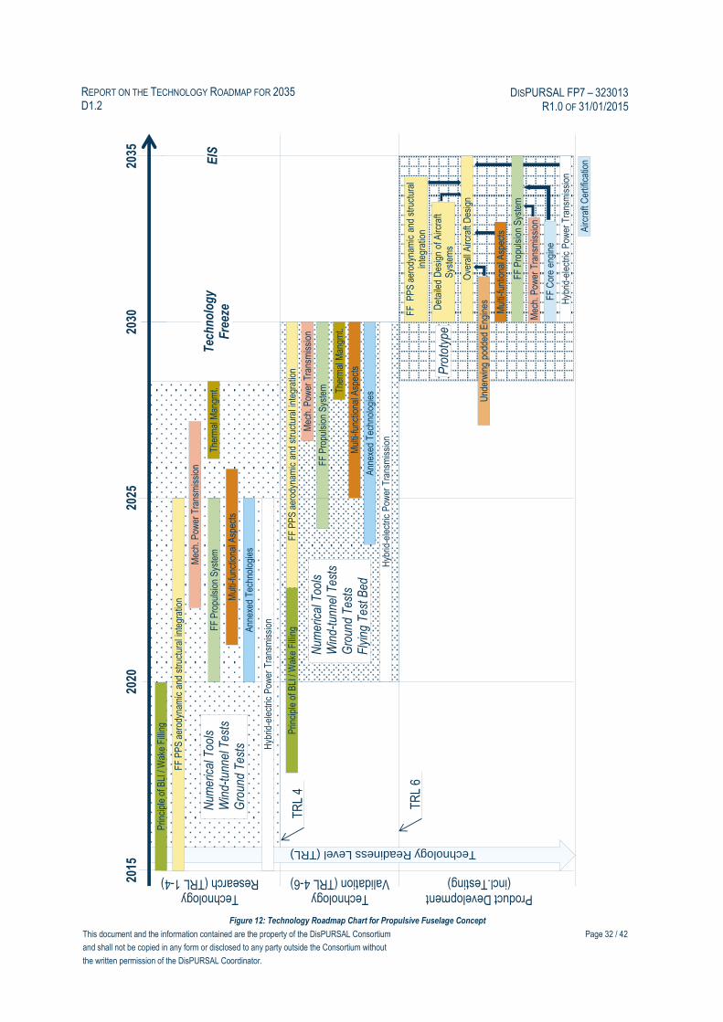
This document and the information contained are the property of the DisPURSAL Consortium
and shall not be copied in any form or disclosed to any party outside the Consortium without
the written permission of the DisPURSAL Coordinator.
Page 32 / 42
REPORT ON THE TECHNOLOGY ROADMAP FOR 2035 D1.2
DISPURSAL FP7 – 323013 R1.0 OF 31/01/2015
Figure 12: Technology Roadmap Chart for Propulsive Fuselage Concept
2015
2035
2025
2020
2030
FF
Pro
puls
ion
Sys
tem
Airc
raft
Cer
tific
atio
n
Technology Research (TRL 1-4)
Technology Validation (TRL 4-6)
FF
Cor
e en
gine
FF
Pro
puls
ion
Sys
tem
FF
PP
S a
erod
ynam
ic a
nd s
truc
tura
l int
egra
tion
FF
PP
S a
erod
ynam
ic a
nd s
truc
tura
l int
egra
tion
FF
PP
S a
erod
ynam
ic a
nd s
truc
tura
l in
tegr
atio
n
Mec
h. P
ower
Tra
nsm
issi
on
Mec
h. P
ower
Tra
nsm
issi
on
Pro
toty
pe
Hyb
rid-e
lect
ric P
ower
Tra
nsm
issi
on
Hyb
rid-e
lect
ric P
ower
Tra
nsm
issi
on
Hyb
rid-e
lect
ric P
ower
Tra
nsm
issi
on
Tec
hn
olo
gy
Fre
eze
Mul
ti-fu
nctio
nal A
spec
ts
Mul
ti-fu
nctio
nal A
spec
ts
Mul
ti-fu
ntio
nalA
spec
ts
Ann
exed
Tec
hnol
ogie
s
Ann
exed
Tec
hnol
ogie
s
Det
aile
d D
esig
n of
Airc
raft
Sys
tem
s
Ove
rall
Airc
raft
Des
ign
EIS
Product Development (incl.Testing)
FF
Pro
puls
ion
Sys
tem
Mec
h. P
ower
Tra
nsm
issi
on
Und
erw
ing
podd
ed E
ngin
es
Prin
cipl
e of
BLI
/ W
ake
Fill
ing
Prin
cipl
e of
BLI
/ W
ake
Fill
ing
The
rmal
Man
gmt. The
rmal
Man
gmt.
TR
L 6
Technology Readiness Level (TRL)
TR
L 4
Num
eric
al T
ools
W
ind-
tunn
el T
ests
Gro
und
Tes
ts
Num
eric
al T
ools
W
ind-
tunn
el T
ests
Gro
und
Tes
ts
Fly
ing
Tes
t Bed

This document and the information contained are the property of the DisPURSAL Consortium
and shall not be copied in any form or disclosed to any party outside the Consortium without
the written permission of the DisPURSAL Coordinator.
Page 33 / 42
REPORT ON THE TECHNOLOGY ROADMAP FOR 2035 D1.2
DISPURSAL FP7 – 323013 R1.0 OF 31/01/2015
Tests with a full-3D model with installed FF and integral empennage in a low-speed wind-tunnel would be mainly aimed at
the determination of the aircraft stability and control aspects. Lift, drag and pitching moment would be determined using an
external 6-component balance. Since it is anticipated that the wake of the wing influences the propulsion system the effects
of flap deflection will be investigated as well. A confirmation high-speed drag measurement for the full configuration
assuming all discrete surfaces neutral should also be conducted.
Tests of the FF with integral empennage in a low-speed wind-tunnel would be aimed at determining boundary layer and BLI
effects on the propulsion system. To arrive at an acceptable relative scale of fuselage boundary layer the length of the model
will be selected and use will be made of Boundary Layer Control in the form of added transition devices and boundary layer
suction, where needed. As the influence of angle-of-attack changes the symmetry of the fuselage boundary layer the aft
positioned fan blades will encounter azimuthal changes in the inflow angles. The effects of this on the overall drag and the
propulsive efficiency could be determined with an external 6-component balance and a Rotating Shaft Balance, respectively.
Results from the wind-tunnel test would be used to validate the numerical tools. These tools can be used to analyse the full
aircraft design (including FF nacelle and integral empennage) in all relevant flight conditions. Since the PFC is based upon
the positive effects of BLI and Wake Filling, therefore, full unsteady CFD simulations of the baseline design need to be
conducted. This would be followed by the optimization of the fuselage aft with FF and integral empennage for the target
Reynolds and Mach numbers. The complete fuselage would then be re-designed and unsteady CFD simulations would be
conducted in order to analyse a fully optimized design. Concurrent to these simulations, aero-acoustic modelling and
analysis would need to be performed. A methodology for the integrated aerodynamic/aero-acoustic design of the fuselage
aft shape including the impact of the propulsion and integral empennage would then be fashioned, thus providing a means to
fashion design rules. All numerical simulations should be supported by an extensive experimental analysis of the concept.
Finally, all experimental results are to be integrated into a consistent aircraft design suite, which would facilitate optimized
future concepts for a given design mission.
Preliminary Power-train and Housing Structural Testing and Simulations
The objective would be to build a scaled FF with integral empennage test rig where the loads are applied mechanically to a
scaled mock-up through a distribution of external actuators. Issues of appropriate similarity and scaling would be addressed.
The scale of the mock-up should be determined at a future date, and particular emphasis needs to be placed upon selecting
scaling laws not only related to the external environment in which the FF operates, but also the loads and associated
response of localized interfacing structures. Attention would need to be paid to avoiding overly small scales where it proves
to be very difficult in distributing loads without imposing localised stress concentrations. Two types of tests are envisioned:
1. Geometric Performance Testing – test the performance of the structure and power-train combined without external
loads
2. Quasi-static Testing and Methods Tuning – apply expected external loads quasi-statically and test performance.
The results would then be compared to the predictions from the model and used to validate the design tools, and if
necessary improve upon them.
3.4.2 Flying Test Bed
To complement computational methods, simulation and ground based physical testing, a suitably scaled manned flying test
bed amenable to atmospheric experimentation and appropriate data acquisition would be necessary in order to validate the
FF device with integral empennage as well as other annexed technologies that either service the artefact or are standalone
systems whose performance is ameliorated by virtue of its presence. When undertaking such a design task and
subsequently performing tests, risk reduction could be enhanced and so pave the way forward for understanding what
constitutes a well-balanced integration approach of identified key technologies for design and development of the first
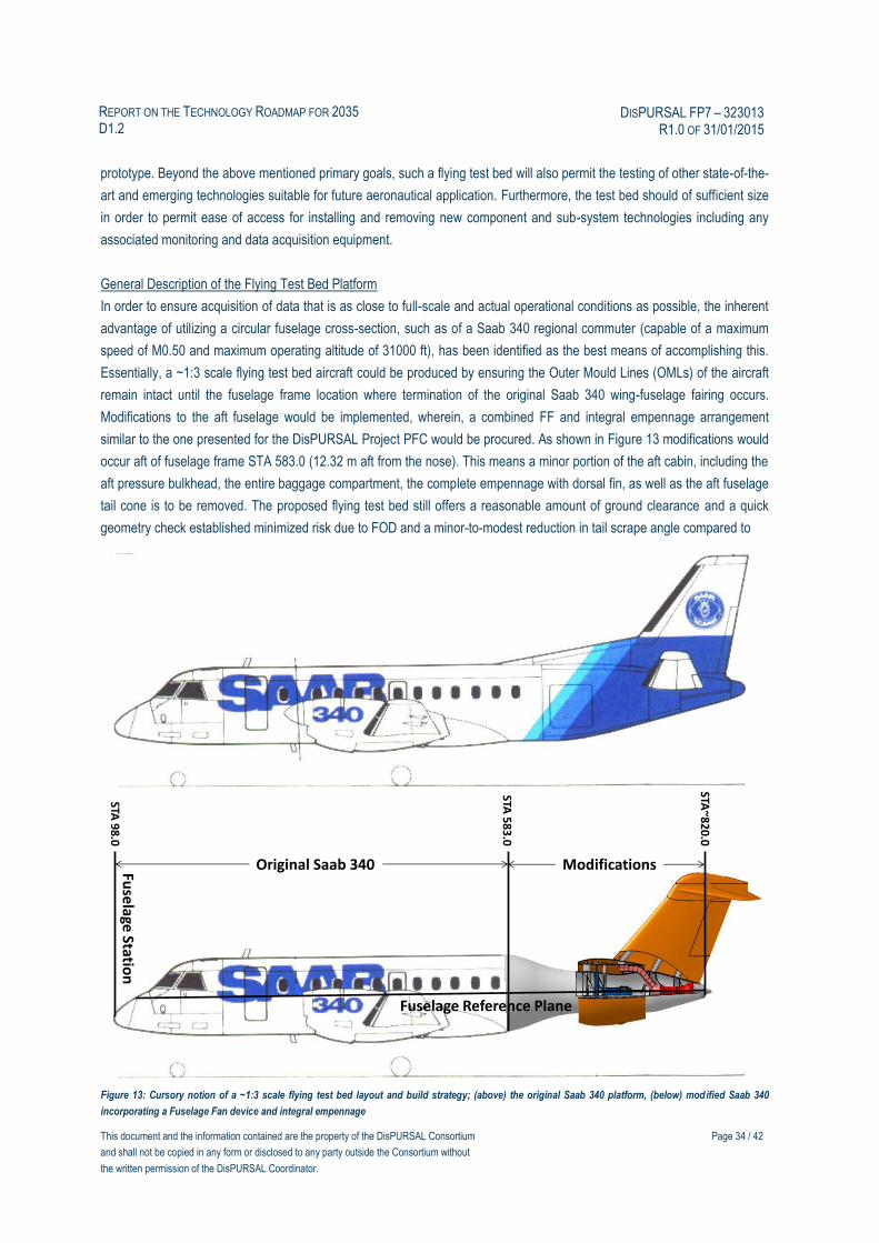
This document and the information contained are the property of the DisPURSAL Consortium
and shall not be copied in any form or disclosed to any party outside the Consortium without
the written permission of the DisPURSAL Coordinator.
Page 34 / 42
REPORT ON THE TECHNOLOGY ROADMAP FOR 2035 D1.2
DISPURSAL FP7 – 323013 R1.0 OF 31/01/2015
prototype. Beyond the above mentioned primary goals, such a flying test bed will also permit the testing of other state-of-the-
art and emerging technologies suitable for future aeronautical application. Furthermore, the test bed should of sufficient size
in order to permit ease of access for installing and removing new component and sub-system technologies including any
associated monitoring and data acquisition equipment.
General Description of the Flying Test Bed Platform
In order to ensure acquisition of data that is as close to full-scale and actual operational conditions as possible, the inherent
advantage of utilizing a circular fuselage cross-section, such as of a Saab 340 regional commuter (capable of a maximum
speed of M0.50 and maximum operating altitude of 31000 ft), has been identified as the best means of accomplishing this.
Essentially, a ~1:3 scale flying test bed aircraft could be produced by ensuring the Outer Mould Lines (OMLs) of the aircraft
remain intact until the fuselage frame location where termination of the original Saab 340 wing-fuselage fairing occurs.
Modifications to the aft fuselage would be implemented, wherein, a combined FF and integral empennage arrangement
similar to the one presented for the DisPURSAL Project PFC would be procured. As shown in Figure 13 modifications would
occur aft of fuselage frame STA 583.0 (12.32 m aft from the nose). This means a minor portion of the aft cabin, including the
aft pressure bulkhead, the entire baggage compartment, the complete empennage with dorsal fin, as well as the aft fuselage
tail cone is to be removed. The proposed flying test bed still offers a reasonable amount of ground clearance and a quick
geometry check established minimized risk due to FOD and a minor-to-modest reduction in tail scrape angle compared to
Figure 13: Cursory notion of a ~1:3 scale flying test bed layout and build strategy; (above) the original Saab 340 platform, (below) modified Saab 340
incorporating a Fuselage Fan device and integral empennage
Fuse
lageStatio
n
Fuselage Reference Plane
Original Saab 340 Modifications
STA 9
8.0
STA 5
83
.0
STA~8
20
.0

This document and the information contained are the property of the DisPURSAL Consortium
and shall not be copied in any form or disclosed to any party outside the Consortium without
the written permission of the DisPURSAL Coordinator.
Page 35 / 42
REPORT ON THE TECHNOLOGY ROADMAP FOR 2035 D1.2
DISPURSAL FP7 – 323013 R1.0 OF 31/01/2015
the original Saab 340.
One concern associated with retaining the original turbo-prop power plant of the Saab 340 is the possible influence of
propwash and corresponding slipstream affects that could be detrimental to quantifying the true nature of performance
exhibited by the FF device. In order to ameliorate this penalizing aspect, one proposal would be to retain the on-wing
integrated landing gear nacelle design and replace the turbo-prop installation with suitable turbofans. Prior to undertaking
such a significant re-design task, the authors recommend a good degree of computational aerodynamics and wind-tunnel
experimental work is performed in establishing whether the propwash and slipstream effects will unduly influence the nature
of flow entering the FF device.
Another possible option for an existing aircraft platform suggested by the Industrial Advisory Board of the DisPURSAL
Project is to utilize the Do 328JET regional commuter (see Figure 14 for notional illustration), and the reasoning associated
with this recommendation deals with the fact that it is an existing turbofan powered aircraft. This aircraft is capable of a
maximum speed of M0.66 and maximum operating altitude of 35000 ft. Issues related to choosing this platform is that of the
high-wing morphology. Firstly, there are concerns the quality of localized flow entering the FF device due to wing borne
downwash could be detrimental, and more importantly, it may inhibit opportunity to design and operate any FF device in an
optimal sense. Prior to undertaking such a significant re-design task, the authors recommend a good degree of
computational aerodynamics and wind-tunnel experimental work is performed in establishing whether the high-wing borne
downwash will unduly influence the nature of flow entering the FF device. Also, by virtue of the high-wing layout, the original
Do 328JET adopted the use of fuselage mounted main landing gears. Unless the complete array of landing gear is
increased in length (accompanied by corresponding changes to the wheel wells for each leg) improved geometric clearance
that can ameliorate potential problems associated with FOD and tail-scrape will not be present.
Figure 14: Cursory notion of a ~1:3 scale flying test bed layout and build strategy; (above) the original Do 328JET platform, (below) modified Do 328JET
incorporating a Fuselage Fan device and integral empennage

This document and the information contained are the property of the DisPURSAL Consortium
and shall not be copied in any form or disclosed to any party outside the Consortium without
the written permission of the DisPURSAL Coordinator.
Page 36 / 42
REPORT ON THE TECHNOLOGY ROADMAP FOR 2035 D1.2
DISPURSAL FP7 – 323013 R1.0 OF 31/01/2015
Outline of Test Plan Goals
Flight test campaigns should be performed using an appropriate flight test vehicle in order to measure aero-airframe/aero-
propulsion properties, to collect data pertaining to performance, handling qualities and assist in formulating operational
procedures. Test plans would comprise functionality tests of the FF system with integral empennage, divided into iron bird
tests, ground tests and validation tests.
The proposed flying test bed would be designed and operated within a 5-10 year time period where efforts would be
expended to increase the maturity of TRLs associated with:
Validating and ratifying the underlying principles of BLI and Wake Filling including the extent of emissions
reduction;
Fuselage Fan aerodynamic, aero-acoustic and structural integration;
Fuselage fan mechanical power-train development;
Fuselage Fan propulsion system design;
Thermal regulation and control strategies;
Development of annexed technologies; and,
Initial understanding of an alternative hybrid-electric power transmission approach for the Fuselage Fan
Although the proposed flying test bed would not be able to investigate aero-airframe and aero-propulsion behavior in the
low-to-mid-transonic flow regime in any detail, meaningful performance data of the FF could be measured up until the flow
regime where onset of transonic effects begin to arise. More importantly, the ~1:3 scale would facilitate a reasonable
understanding of FF behavior during low-speed operations, i.e. high angle-of-attack and/or large side-slip angles and/or
cross-wind operations, owing to the Reynolds number in which the test bed aircraft will operate.

This document and the information contained are the property of the DisPURSAL Consortium
and shall not be copied in any form or disclosed to any party outside the Consortium without
the written permission of the DisPURSAL Coordinator.
Page 37 / 42
REPORT ON THE TECHNOLOGY ROADMAP FOR 2035 D1.2
DISPURSAL FP7 – 323013 R1.0 OF 31/01/2015
4. Critical Appraisal and Recommendations of the Industrial Advisory Board
The following are the general comments expressed by the Industrial Advisory Board (IAB):
The DisPURSAL Project was very well organized, the team of Bauhaus Luftfahrt, Airbus Group Innovations,
ONERA and CIAM worked well together. Comprehensive reports have been delivered. Previous IAB
recommendations have been taken into account. With respect to the project objectives and the overall research
aspects the IAB Members would like give the project a high rating.
Project topics “Propulsive Fuselage Concept” (PFC) and “Distributed Multiple-Fans Propulsion Concept” (DMFC)
are of significant interest as possible technology bricks that offer potential to achieve SRIA 2050 emission
objectives (block fuel CO2-emissions, NOx-emissions, external noise).
Overall assessment of the concepts including their potential contribution to emission (CO2-emissions, NOx-
emissions, external noise) reduction is well appreciated.
Uncertainty aspects in form of best and worst cases analysis have been taken into account to achieve the most
robust results based on the limited resources available in the DisPURSAL Project.
4.1 Distributed Multiple-Fans Concept
For the DMFC the DisPURSAL Project has shown a potential block fuel benefit of 8-10% (turbo fan engines) and increased
Operational Empty Weight (OEW) of approximately 3%. Hybrid-electric concepts show a marginal block fuel increase of
1.5% and a significant OEW increase.
Key aerodynamic issues are like for the PFC drag analysis and fan inflow distortion aspects. Even more important is the
mechanical maturation of a distributed propulsion concept:
Mechanical maturation of a DMFC including power transmission, dynamic load scenarios, and failure cases. Can
these concepts be designed with high reliability? How does this influence its mass?
More detailed 3D RANS-based drag analysis study to further mature the theoretical overall drag reduction
potential at flight Reynolds-number (see PFC), including trimmed aircraft; the IAB considers that quoted block fuel
reduction is somewhat small compared to other externally published values without Boundary Layer Ingestion
(BLI);
3D RANS-based analysis of fan inflow distortions (see PFC);
No need for LES method here, focus should be on fast RANS methods for aerodynamic design; see Section 2.3 of
the D1.2 report;
More robust analysis of flight mechanics and control aspects regarding yaw stability; yaw stability very likely
cannot be achieved for civil aircraft without a vertical tail although the engine are close to the centerline; additional
drag has to be taken into account;
How robust is the statement that OEW increase is limited to 3%? More detailed investigations including load and
failure cases are necessary;
More detailed aero-acoustic assessment required, including noise shielding effects; embedding the engines may
support BLI and noise shielding; and,
The design of fans which can tolerate the inflow distortions (particularly during take-off) is a challenge but should
be possible. However the fan will, for example, need more and thicker blades than normally used and the
efficiency will decrease and the weight will increase. These effects have to be taken into account.

This document and the information contained are the property of the DisPURSAL Consortium
and shall not be copied in any form or disclosed to any party outside the Consortium without
the written permission of the DisPURSAL Coordinator.
Page 38 / 42
REPORT ON THE TECHNOLOGY ROADMAP FOR 2035 D1.2
DISPURSAL FP7 – 323013 R1.0 OF 31/01/2015
4.2 Propulsive Fuselage Concept
With its central engine installation, the PFC configuration takes full advantage of the increased propulsive efficiency linked to
the fuselage BLI and benefits from an interesting block fuel reduction between 5% and 11% while OEW is increased by
approximately 6%. This is indeed very promising but according to experience revolutionary technologies should at least
deliver an advantage of 15% because of additional unaccounted negative effects. Notwithstanding this, it is acknowledged
when considering the zero lift drag only, which is where the focus is placed, this technology has the potential of delivering a
benefit of 10-15%.
The resulting tri-jet layout is economically penalized by its three propulsion systems and by the complexity of the central
engine installation; the resulting economical advantage is considered to be marginal at the best, whatever the fuel and
engine propulsion system prices. Furthermore, the inflow distortion due to BLI may lead to a fan efficiency degradation,
increase of fan noise and vibration as well as stability problems regarding surge margin. These are major aspects which
need future investigation.
Therefore, it is recommended to further mature these benefits. This means the following key issues that are part of Section 3
of the D1.2 report should be addressed in any follow-on projects:
Maturation of potential for block fuel reduction when aircraft design speed is reduced, including impact on aircraft
operations; comparison to SoAR with identical design speed; is cruise speed a critical parameter for BLI
application?
More detailed 3D drag analysis study to further mature the theoretical overall drag reduction potential of PFC at
flight Reynolds number;
3D analysis of fan inflow distortions including fan surge for specific key points of the flight envelope (cruise points,
take-off/landing, side-wind, at flight Reynolds number respectively); questions to be answered: is inflow distortion a
“show stopper” or can it be handled by, e.g. integrated/coupled external-aero-fan redesign, by adaptive inflow
control or other means? Are fan guide vanes necessary or can they be avoided?
3D flow analysis of S-duct losses; including core engine inflow distortion aspects to possibly mature results
towards “best scenarios”;
Aerodynamic validation aspects can benefit from other projects; nevertheless, identification of aerodynamic cases
that may benefit from scaled wind-tunnel tests is beneficial;
More detailed analysis of design/off-design static and dynamic load cases for sizing of the fuselage-engine-tail
section to achieve a more robust mass estimation;
Further aero-acoustic assessment of the configuration, source characteristics;
Aircraft using more than 2 engines cause high costs and are less efficient. Therefore novel concepts should be
considered, for example, one aft fan driven by two gas-turbines; and,
The electrically driven fan is an interesting option too. If the fan does not deliver thrust but only BLI the necessary
power should be reduced. Assuming very advanced parameters for the electric motor and generator (power to
weight ratio, efficiency, ..) what would then be the mission fuel burn reduction?
This document and the information contained are the property of the DisPURSAL Consortium
and shall not be copied in any form or disclosed to any party outside the Consortium without
the written permission of the DisPURSAL Coordinator.
Page 39 / 42
REPORT ON THE TECHNOLOGY ROADMAP FOR 2035 D1.2
DISPURSAL FP7 – 323013 R1.0 OF 31/01/2015
5. Conclusion
In this report, a technology roadmap has been derived for the Distributed Multiple-Fans Concept (DMFC) and the Propulsive
Fuselage Concept (PFC) providing a research guideline to advance required technologies to sufficient maturity for a targeted
Entry-Into-Service (EIS) year of 2035. After a short recapitulation of the investigated concepts and the respective key
findings, the essential technologies for each concept have been summarized and evaluated regarding their current
Technology Readiness Level (TRL). In case of the DMFC, the development of a distortion-tolerant fan and means to avoid
flow separation upstream of the fan assembly appear to be the most immature technology fields, followed by a thorough and
validated design of a mechanical transmission system including the associated cooling system. In case of the PFC, the least
maturity was also identified, namely, the knowledge of distortion-tolerant fan design, flow separation avoidance, as well as
structural integration of core engine and fan into the rear fuselage section in proximity of critical aircraft control surfaces
(empennage). Furthermore, a more detailed investigation of the effects and performance in the whole flight envelope
including abnormal and emergency conditions has to be performed. Necessary development steps have been defined to
advance the technologies up to the required maturity EIS 2035, and the respective technology roadmaps for both concepts
have been presented and visualized. On condition that the considered development steps are addressed and conducted as
proposed, the targeted TRL 6 maturity by year 2030 and the EIS year by 2035 appear to feasible for both concepts.

This document and the information contained are the property of the DisPURSAL Consortium
and shall not be copied in any form or disclosed to any party outside the Consortium without
the written permission of the DisPURSAL Coordinator.
Page 40 / 42
REPORT ON THE TECHNOLOGY ROADMAP FOR 2035 D1.2
DISPURSAL FP7 – 323013 R1.0 OF 31/01/2015
6. References
1. CIAM2. "Multi-Disciplinary Design Results on Distributed Propulsion". DisPURSAL Deliverable D2.2. 9 December 2014.
2. Bauhaus Luftfahrt e.V. Multi-disciplinary Design Results on Propulsive Fuselage. DisPURSAL Deliverable D3.2, issued
31.10.2014.
3. Kim, H. D. Distributed propulsion vehicles. 27th International Congress of the Aeronautical Sciences, Nice, France,
September 7-12, 2014.
4. Steiner, H.-J., Seitz, A., Wieczorek, K., Plötner, K., Isikveren, A.T., Hornung, M. Multi-Disciplinary Design and
Feasibility Study of Distributed Propulsion Systems. 28th International Congress of the Aeronautical Sciences : Brisbane,
Australia, 2012.
5. Isikveren, A.T., et al., et al. "Recent Advances in Airframe-Propulsion Concepts with Distributed Propulsion". 29th
Congress of the International Council of the aeronautical Sciences, St. Petersburg, Russia. September 2014.
6. CIAM1. Down-Selection of Distributed Propulsion Concepts: DisPURSAL Deliverable D2.1. 5 August 2013.
7. Seitz, A., Bijewitz, J., Kaiser, S., Wortmann, G. Conceptual Investigation of a Propulsive Fuselage Aircraft Layout. DOI:
10.1108/AEAT-06-2014-0079. Aircraft Engineering and Aerospace Technology Journal. Volume 86, Issue 6, October 2014.
8. Seitz, A., Gologan, C. Parametric Design Studies for Propulsive Fuselage Aircraft Concepts. 4th CEAS Air & Space
Conference, Linköping, Sweden, September 2013.
9. Bauhaus Luftfahrt e.V. DisPURSAL SoAR & 2035R Reference Aircraft Definition. DisPURSAL project internal report,
issued 10th December, 2013.
10. MIT. "N+3 Aircraft Concept Design and Trade Studies FINALREPORT". Volume I. 2010.
11. Florea, R.V., et al., et al. "Aerodynamic Analysis of a Boundary-Layer-Ingesting Distortion-Tolerant Fan". ASME Turbo
Expo 2013: Turbine Technical Conference and Exposition. Volume 6B: Turbomachinery, ISBN: 978-0-7918-5523-2, June
2013.
12. Cambier, L., Heib , S. and Plot, S. "The ONERA elsA software: Input from Research and Feedback from Industry". 28th
International Congress of the Aeronautical Sciences, Brisbane, Australia. September 2012.
13. Destarac, D. "Far-Field / Near-Field Drag Balance and Applications of Drag Extraction in CFD". VKI Lecture Series
2003, CFD-based Aircraft Drag Prediction and Reduction, von Karman Institute for Fluid Dynamics, Rhode saint Genèse.
February 2003.
14. NASTRAN. www.mscsoftware.com.
15. http://www.purepowerengine.com/news.htm, cited 15.01.2015. [Online]
16. von der Bank, R. Low EMissions COre-Engine TEChnologies (LEMCOTEC). FP7-AAT-2011-RTD-1, Proposal No.
283216, European Commission Directorate General for Research and Innovation, December 2010.
17. Merkl, E. Engine BREAK-through components and sub-systems (E-BREAK). FP7-AAT-2012-RTD-1, Proposal No.
314366, European Commission Directorate General for Research and Innovation, December 2011.
18. Silva, M. ENgine mOdule VAlidators (ENOVAL). FP7-AAT-2012-RTD-1, Proposal No. 314366, European Commission
Directorate General for Research and Innovation, December 2011.
19. Mattingly, J., Heiser, W., Pratt, D. Aircraft Engine Design. 2nd Edition, AIAA Education Series, 2002.
20. Godard , J.-L. Semi-Buried Engine Installation: the NACRE Project Experience. 27th International Congress of the
Aeronautical Sciences, Nice, France. September 2010.
21. Bauhaus Luftfahrt e.V. Down-Selection of Propulsive Fuselage Concepts. DisPURSAL Deliverable D3.1, issued 31
July 2013.
22. U.S. Department of Transportation, Federal Aviation Administration. Design Considerations for Minimizing Hazards
Caused by Uncontained Turbine Engine and Auxiliary Power Unit Rotor Failure. Advisory Circular 20-128A, July 18, 1995.

This document and the information contained are the property of the DisPURSAL Consortium
and shall not be copied in any form or disclosed to any party outside the Consortium without
the written permission of the DisPURSAL Coordinator.
Page 41 / 42
REPORT ON THE TECHNOLOGY ROADMAP FOR 2035 D1.2
DISPURSAL FP7 – 323013 R1.0 OF 31/01/2015
23. Asbury, S., Yetter, J. Static Performance of Six Innovative Thrust Reverser Concepts for Subsonic Transport
Applications. Summary of the NASA Langley Innovative Thrust Reverser Test Program, NASA TM-2000-210300, July 2000.
24. Campbell, F. Structural Composite Materials. ASM International, 2010.
25. Flinn, B. Improving Adhesive Bonding of Composites through Surface Characterization. The Joint Advanced Materials
and Structures Center of Excellence, 2009.
26. Paton, R. et al. A Breakthrough in the Assembly in Aircraft Composite Structures. 25th International Congress of the
Aeronautical Sciences, Hamburg, Germany, 2006.
27. Lee, D. et al. Active Flow Control Bump Design Using Hybrid Nash-Game Coupled to Evolutionary Algorithms.
Proceedings of 5th European Conference on Computational Fluid Dynamics, Lisbon, Portugal, 2010.
28. Robert, J. Drag reduction: an industrial challenge: Special Course on Skin Friction Drag Reduction. AGARD-R-786,
Paper No. 2, 1992.
29. Reneaux, J. Overview on Drag Reduction Technologies for Civil Transport Aircraft. European Congress on
Computational Methods in Applied Sciences and Engineering, ECCOMAS 2004.
30. Walsh, M. Riblets. AIAA Viscous Flow Drag Reduction, Vol. 123, pp. 203-261, 1990.
31. Drela, M. "Power Balance in Aerodynamics Flows". AIAA Journal, Vol. 47, No. 7, pp.1761–1771, DOI: 10.2514/1.42409.
2009.
32. Arntz, A., et al., et al. “Exergy-based Aircraft Aeropropulsive Performance Assessment: CFD Application to Boundary
Layer Ingestion". 32nd AIAA Applied Aerodynamics Conference, Atlanta, GA, USA. June 2014.
33. Baier, H. Morphing Enabling Technologies for Propulsion System Nacelles (MorphElle). FP7-AAT-2012-RTD-L0,
Proposal No. 341509, European Commission Directorate General for Research and Innovation, October 2013.
34. Atinault, O., et al., et al. “Numerical and Experimental Aerodynamic Investigations of Boundary Layer Ingestion for
Improving Propulsion Efficiency of Future Air Transport". 31st AIAA Applied Aerodynamics Conference, San Diego, CA,
USA. June 2013.
35. Hall, C., Gunn, E., Perovic, D. Fan systems for Boundary Layer Ingestion. IMechE Special Conference on Distributed
Propulsion, London, UK, 18 November 2014.
36. Smith, B., Yagle, P. and Hooker, J. Reduction of Aft Fuselage Drag on the C-130 Using Microvanes. 51st AIAA
Aerospace Sciences Meeting including the New Horizons Forum and Aerospace Exposition, 7-10 January 2013, Grapevine,
Texas, AIAA 2013-0105, 2013.
37. European Commission. Horizon 2020 - Work Programme 2014-2015, Annex G: Technology Readiness Levels.

This document and the information contained are the property of the DisPURSAL Consortium
and shall not be copied in any form or disclosed to any party outside the Consortium without
the written permission of the DisPURSAL Coordinator.
Page 42 / 42
REPORT ON THE TECHNOLOGY ROADMAP FOR 2035 D1.2
DISPURSAL FP7 – 323013 R1.0 OF 31/01/2015
7. Annex
Definition of Technology Readiness Levels (37)
TRL 1 – basic principles observed
TRL 2 – technology concept formulated
TRL 3 – experimental proof of concept
TRL 4 – technology validated in lab
TRL 5 – technology validated in relevant environment (industrially relevant environment in the case of key enabling
technologies)
TRL 6 – technology demonstrated in relevant environment (industrially relevant environment in the case of key enabling
technologies)
TRL 7 – system prototype demonstration in operational environment
TRL 8 – system complete and qualified
TRL 9 – actual system proven in operational environment (competitive manufacturing in the case of key enabling
technologies; or in space)