comsol news
TRANSCRIPT

Life-Saving Heart Pump Abbott Designs Left Ventricular Assist Device with MultiphysicssPAGE 7
COMSOL NEWS
www.comsol.com
SPECIAL EDITION BIOMEDICAL

INTERACT WITH THE COMSOL COMMUNITY BLOG comsol.com/blogsFORUM comsol.com/forum LinkedIn™ linkedin.com/company/comsol-inc-Facebook® facebook.com/multiphysics Twitter® twitter.com/@COMSOL_Inc
© 2021 COMSOL. COMSOL, COMSOL Multiphysics, Capture the Concept, COMSOL Desktop, COMSOL Server, COMSOL Compiler, and LiveLink are either registered trademarks or trademarks of COMSOL AB. All other trademarks are the property of their respective owners, and COMSOL AB and its subsidiaries and products are not affiliated with, endorsed by, sponsored by, or supported by those trademark owners. For a list of such trademark owners, see www.comsol.com/trademarks.
LinkedIn is a trademark of LinkedIn Corporation and its affiliates in the United States and/or other countries. Facebook is a registered trademark of Facebook, Inc. TWITTER, TWEET, RETWEET and the Twitter logo are trademarks of Twitter, Inc. or its affiliates.
Although biomedical engineering can be defined in just a few words — the use of engineering methods in biological and medical healthcare applications — it spans an amazingly wide range of corresponding applications. Simulation is broadly used for research and development across the biomedical engineering field, from pharmaceutical process development to individualized medicine for patients. This special edition of COMSOL News contains a collection of stories in which the COMSOL Multiphysics® simulation software is used in healthcare development and to provide insight into common biomedical engineering challenges.
One such challenge is the variability of patients who will benefit from biomedical R&D through improved medical devices, safer medicines, more precise drug delivery systems, and more. The use of simulation as a tool for virtual testing is especially helpful when accounting for the variability of the human body, both in terms of shape and tissue properties. When these tools are placed in the hands of medical professionals as easy-to-use apps, simulation can be used for decision making on an actual treatment for a specific patient.
The examples in this special edition of COMSOL News show the broad use of simulation in the biomedical engineering field. You will see the efforts made to improve pharmaceutical processes and the safety and efficacy of drugs produced. You will also see how simulation supports the design and innovation of medical devices, such as left ventricular assist device (LVAD) heart pumps, passive vaccine storage devices, therapeutic cell sorters, and hematology analyzers. We hope that by reading these articles, you will gain insight into how biomedical design projects often benefit from using simulation, and how multiphysics simulation contributes to innovation in biomedical engineering. Enjoy!
Nicolas Huc COMSOL
Multiphysics Simulation in Biomedical Engineering
INTRODUCTION
Simulation apps streamline workflows in the biopharma industry
PAGE 10
Cover image reproduced with permission of Abbott, © 2021. All rights reserved. Abbott ‘A’ and HeartMate 3 are trademarks of Abbott or its related companies.

TABLE OF CONTENTS
SIMULATION-BASED PRODUCT DEVELOPMENT
16 Simulation Advances the Design of a Microfluidic Therapeutic Cell SorterThe Technology Partnership (TTP), UK
SIMULATION IN THE CLASSROOM
34 Adding Quantitative Systems Pharmacology to the Pharmaceutical Sciences Curriculum The University of Oklahoma College of Pharmacy, OK, USA
MULTIPHYSICS INNOVATION
14 Innovative Thermal Insulation Techniques Bring Vaccines to the Developing WorldIntellectual Ventures, WA, USA
22 Optimizing Hematology Analysis: When Physical Prototypes Fail, Simulation Provides the Answers HORIBA Medical, France
26 MRI Tumor-Tracked Cancer Treatment University of Alberta/Cross Cancer Institute, AB, Canada
32 Reliable Structures and Wearable Systems Call for Multiphysics Simulation STMicroelectronics, Italy
36 Medtronic Advances Ablation Technology with Multiphysics Simulation Medtronic, CO, USA
GUEST EDITORIAL
40 Rethinking Medical Device Design in a Post-COVID-19 WorldBy Daniel Smith, Emphysys, MA, USA
RESEARCH SPOTLIGHT
19 Simulating the Release Mechanism in Drug-Eluting StentsBoston Scientific, MN, USA
28 3D Parametric Full Eye Model Gives 20+ Years of Better Vision Kejako, Switzerland
DEMOCRATIZING SIMULATION
10 Multiphysics Modeling in the Biopharma Industry Amgen, MA, USA
DESIGN OPTIMIZATION
4 On the Cutting Edge of Hearing Aid ResearchKnowles Corporation, IL, USA
7 Enhancing Performance and Safety of Medical Implantable Devices with Multiphysics SimulationAbbott Laboratories, CA, USA
TABLE OF CONTENTS

4 COMSOL NEWS
Knowles Corporation, IL, USA
ON THE CUTTING ON THE CUTTING EDGE OF HEARING EDGE OF HEARING AID RESEARCHAID RESEARCH
by GARY DAGASTINE
DESIGN OPTIMIZATION
Engineers at Knowles bring the hearing aid industry together to fight feedback with multiphysics simulation.
FIGURE 1 A typical BTE hearing aid includes microphones, vibration insulation, and a receiver, among other components. The tight spacing of these components invites troublesome acoustic and mechanical feedback. (Image credit: Knowles Corp.)
In the United States, nearly 20% of the population is reportedly hearing impaired; that figure could be higher because many people are reluctant to admit they have a hearing problem. Those who are treated rely on miniature and discreet hearing aid devices to improve their hearing, hence their quality of life. Significant R&D effort is required to bring a hearing instrument from a prototype stage to a marketable hearing aid device.
Engineers face daily technical challenges in hearing aid design. Feedback is a major issue that leads to high-pitched squealing or whistling, and limits the amount
of gain the aid can provide. “Feedback usually occurs when a hearing aid’s microphone picks up sound or vibration inadvertently diverted from what is being channeled into the ear canal and sends it back through the amplifier, creating undesirable oscillations,” explains Brenno Varanda, a senior electroacoustic engineer at Knowles Corp. in Itasca, IL.
“For many of Knowles’ customers, designing a new hearing aid is a costly, time-intensive process that could take anywhere from 2 to 6 years to complete,” Varanda explains. Accurate modeling helps designers select speakers, refine vibration isolation mounts, and package components to reduce the amount of speaker energy that is fed back to the microphone. The industry is in dire need of simple transducer models that will expedite that process and provide more effective options to consumers. Complete models of speakers and microphones are quite complex and incorporate many factors that are not necessary for feedback control. “While understanding the electromagnetic, mechanical, and acoustic physics of our transducers is important to transducer designers at Knowles, all of that complexity is not necessarily useful for our customers,” Varanda says.
As a global leader and market supplier of hearing aid transducers, intelligent audio, and specialty acoustic components, Knowles took a multilateral initiative to develop transducer vibroacoustic models that are easy to implement and compatible with its hearing health customers. The models are intended to help hearing aid designs graduate from a prototype stage to a final product in a more efficient manner without having to sacrifice accuracy.
» HEARING AID DESIGN AND FEEDBACKWhen designing hearing aids, two major conflicting requirements must be accounted for by engineers. They must be compact and unobtrusive, yet still capable of providing a powerful sound output to overcome the user’s hearing loss. The user is far more likely to wear a hearing aid if they are discreet and lightweight. This makes solving the feedback issue more challenging. “A common design challenge is to cram
COMSOL NEWS 5
all the hardware components into the smallest space possible without causing feedback instability,” Varanda continues.
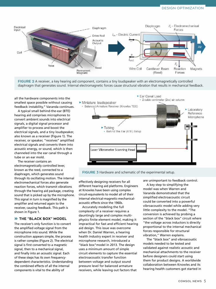
A typical small behind-the-ear (BTE) hearing aid comprises microphones to convert ambient sounds into electrical signals, a digital signal processor and amplifier to process and boost the electrical signals, and a tiny loudspeaker, also known as a receiver (Figure 1). The receiver, or speaker, “receives” amplified electrical signals and converts them into acoustic energy, or sound, which is then channeled into the ear canal through a tube or an ear mold.
The receiver contains an electromagnetically controlled lever, known as the reed, connected to a diaphragm, which generates sound through its oscillating motion. The internal electromechanical forces also generate reaction forces, which transmit vibrations through the hearing aid package, creating sound that is picked up by the microphone. This signal in turn is magnified by the amplifier and returned again to the receiver, causing feedback. This path is shown in Figure 1.
» THE “BLACK BOX” MODELThe receiver’s only function is to convert the amplified voltage signal from the microphone into sound. While the construction appears simple, the process is rather complex (Figure 2). The electrical signal is first converted to a magnetic signal, then to a mechanical signal, and finally into an acoustic signal. Each of these steps has its own frequency-dependent characteristics. Understanding the combined effects of all the internal components is vital to the ability of
effectively designing receivers for all different hearing aid platforms. Engineers at Knowles have been using complex circuit-equivalents to model all of their internal electrical-magnetic-mechanical-acoustic effects since the 1960s.
Accurately modeling the full complexity of a receiver requires a dauntingly large and complex multi-physics finite element model, making it impractical for fast and efficient hearing aid design. This issue was overcome when Dr. Daniel Warren, a hearing health industry expert in receiver and microphone research, introduced a "black box"model in 2013. The design uses a minimum amount of simple circuit elements to capture the essential electroacoustic transfer function between voltage and output sound pressure level for balanced armature receivers, while leaving out factors that
DESIGN OPTIMIZATION
FIGURE 2 A receiver, a key hearing aid component, contains a tiny loudspeaker with an electromagnetically controlled diaphragm that generates sound. Internal electromagnetic forces cause structural vibration that results in mechanical feedback.
FIGURE 3 Hardware and schematic of the experimental setup.
are unimportant to feedback control. A key step to simplifying the
model was when Warren and Varanda demonstrated that the simplified electroacoustic circuit could be converted into a powerful vibroacoustic model while adding very little complexity to the model. “The conversion is achieved by probing a section of the "black box" circuit where "the voltage across inductors is directly proportional to the internal mechanical forces responsible for structural vibration,” Warren explains.
The “black box” and vibroacoustic models needed to be tested and validated against realistic acoustic and mechanical attachments to the receiver before designers could start using them for product designs. A worldwide collaboration between Knowles and its hearing health customers got started in

6 COMSOL NEWS
2014 to validate the models using the COMSOL Multiphysics® software and industry standard tests.
» WORKING TOGETHER ON VALIDATIONTo validate the models, engineers needed to measure the acoustic output and vibration forces at the same time, using a structure that could be easily modeled in FEA. Like common hearing aid tests, this test involved connecting a receiver to a short section of tubing leading to an enclosed cavity with a two cubic centimeter (2 cc) volume, which is a standardized ear canal acoustic load as shown in Figure 3. The acoustic pressure inside the cavity is measured with a laboratory-grade microphone.The receiver was also measured using a complex tubing assembly, similar to a BTE hearing instrument, to help verify the robustness of the model. The long tubing in this design varies in diameter
FIGURE 4 Simulation force and displacement results at 3 kHz of the receiver and silicone tube attachment.
FIGURE 5 Left: Measured (dotted line) vs. simulated (solid line) sound pressure level inside a 2-cc coupler. Right: Measured (dotted line) vs. simulated (solid line) forces and torque acting on the receiver.
and is long enough to support multiple acoustic resonances. At the same time the acoustic output was being measured, the receiver’s structural motion was captured by a laser vibrometer. Both translational and rotational motion were measured by observing the motion at multiple points on the surface of the receiver housing.
Warren and Varanda collaborated with several Knowles customers to perform the measurements described above. With the help of COMSOL Multiphysics, they were able to implement the simplified vibroacoustic circuit model into a simulated replica of the test setup described above. The simulation couples the mechanical interaction between the motion of the receiver and the silicone tubing attachment, thermoviscous losses within the various tubing cross sections, and acoustic pressure loads inside the cavity and tubing with the internal electro-magnetic-acoustic effects in the “black box” receiver model.
The COMSOL model revealed the dependence of the output pressure and mechanical forces on the applied voltage, frequency, and material properties. Figure 4 shows the displacement results from the simulation at 3 kHz and the reaction forces coupled to the receiver.
When Varanda compared the results of simulations with the physical measurements, they showed excellent agreement (Figure 5). The forces acting on the diaphragm and the reed are acoustically dependent on the output sound pressure. However, the coupling between the forces acting on the diaphragm with the structural
reaction forces proves to be, as expected, directly proportional.
» SPREADING THE KNOWLEDGEKnowles shares their model to empower engineers at other hearing aid companies to solve their own system feedback troubles. With a complete representation of the acoustic, mechanical, and electromagnetic behavior inside the hardware, designers are well set up to virtually optimize their products.
“COMSOL® is one of the few modeling and simulation tools that can easily couple the lumped 'black box' receiver circuit with acoustics and solid mechanics,” says Varanda. “Until now, verifying and optimizing hearing aid designs has been as much art as science. We will be very happy to see new hearing instrument designs that have benefitted from these models.”
By joining forces, the intercompany effort has made it easier for everyone in the hearing health industry. “Ultimately, hearing aid designers do not want to get bogged down with complex transducer models and time-consuming simulations. They simply want to focus on their own design and to swap transducers in and out to see how everything will work together,” he adds. “This COMSOL model enables them to do this. The behavior of hundreds of transducers can be easily compared for one hearing aid package.”
Hearing aid designers now have the capability to reduce feedback and improve overall performance better, faster, and more economically than before, which will lead to options for people who are hearing impaired.
DESIGN OPTIMIZATION

COMSOL NEWS 7
Abbott Laboratories, CA, USA
ENHANCING PERFORMANCE ENHANCING PERFORMANCE AND SAFETY OF MEDICAL AND SAFETY OF MEDICAL IMPLANTABLE DEVICES IMPLANTABLE DEVICES WITH MULTIPHYSICS WITH MULTIPHYSICS SIMULATIONSIMULATION
by SARAH FIELDS
DESIGN OPTIMIZATION
At Abbott Laboratories, ventricle assist devices are developed to improve the lives of patients with heart failure. Numerical simulation is used throughout the design process to characterize diverse concurrent aspects of the design, from thermal effects and fluid dynamics to power transfer.
FIGURE 1 An LVAD pump is responsible for circulating oxygen-rich blood throughout the body. Image courtesy of Abbott Laboratories.
The development of a device meant to assist or completely replace functioning of the heart is undeniably complex. This design process involves immense challenges, from supplying power to the device to ensuring it does not interfere with normal biological functioning. Researchers at Abbott Laboratories use multiphysics simulation to engineer left ventricular assist devices (LVADs) in an ongoing effort to improve the outlook and quality of life for patients with heart failure.
The condition typically begins with the left side of the heart, as the left ventricle is responsible for pumping oxygen-rich blood throughout the body a greater distance than the right ventricle, which pumps blood through the lungs. Often, in patients with a poorly functioning left ventricle, an LVAD (see Figure 1) can provide mechanical circulatory support.
The ventricle assist device is one of the

8 COMSOL NEWS
most complex machines ever implanted in a human being. An LVAD must circulate the entire human blood stream and support life, as well as be compatible with the internal environment of the human body. Thoratec, now part of Abbott, brought LVADs to a wide market in 2010, after years of clinical trials.
» DESIGNING A POWERFUL, EFFICIENT, AND HEMOCOMPATIBLE PUMP The design of an LVAD must take many factors into consideration. The device must be small enough to connect to the heart and be made of compatible materials and geometry that permit the device to reside in the body without being rejected. Fluid dynamics, power supply, and thermal management must also be considered. As multiple interacting physical effects must be accounted for at each area of development, multiphysics simulation is vital to the design process.
Freddy Hansen, Staff Research Physicist, at Abbott, uses his expertise in physics and mathematical modeling to characterize complex implantable medical devices like LVADs before experimental studies.
Hansen has been using the COMSOL Multiphysics® software since 2011 and has since created more than 230 models that address a wide range of design challenges pertaining to the unique physics of artificial pumping devices.
“I use COMSOL Multiphysics every day, from proof-of-concept models to quite sophisticated simulations featuring detailed CAD geometries and coupled physics. I work with some complex models for months before I have taken all of the information I want from them.”
DESIGN OPTIMIZATION
FIGURE 2 External equipment of an LVAD. Image courtesy of Abbott Laboratories.
With each generation of LVADs introduced to market, improvements are made that contribute to enhanced safety and quality of life for the patient. Research and development efforts at Abbott are centered on improving biocompatibility, hemocompatibility, and immunocompatibility, such that the device does not illicit an adverse immune response or interfere with other bodily systems.
Geometry and size of the device play an important role in its overall effectiveness. To implant the LVAD, the surgeon connects one end of the LVAD to the left ventricle and the other end to the ascending aorta (see Figure 2). If the device is smaller, it is less cumbersome and less likely to interfere with neighboring organs or tissue. Simulation allows for the evaluation of changes in size or geometry of the LVAD design before implementation in a physical prototype.
» OPTIMIZING LVAD DESIGN FOR BIOCOMPATIBILITYMany simulations were used in the development of the centrifugal pump of the LVAD. One challenge associated with engineering these devices is the prevention of blood clotting in any space in or around the pump. To address this, a magnetically levitated rotor was developed, which eliminated the need for ball bearings and other components with geometries that might promote clotting. Hansen used the Rotating Machinery modeling technology available in the software to model both the magnetically levitated rotor and turbulent fluid flow.
A permanent magnet in the pump rotor is driven by coils in the stator, which exert a torque on the rotor and provide active control of the position of the rotor axis. The vertical position — or levitation — of the rotor is accomplished by magnetic field line tension and does not need active control. The rotor receives blood axially and redirects it radially, into the volute, or fluid collector (see Figure 3). Some of the blood flows back and around the outer edge of the rotor and flows back into the rotor inlet, resulting in a constant washing of the blood, which serves to eliminate places where the blood can stagnate and clot.
Another significant advance was the development of a pump system with
FIGURE 3 Visualization of the magnetically levitated rotor, which eliminates the need for ball bearings and other components with geometries that might promote clotting. Here, the magnitude and direction of the magnetic field in the rotor, as well as the magnitude of the magnetic field in the stator are shown (top left). 3D CFD simulation depicting fluid velocity within the pump chamber (bottom left). Diagram of the centrifugal pump of an LVAD (right).

COMSOL NEWS 9
pulsatile flow, rather than continuous flow, which more closely mimics a functioning heart. The pulsatile flow aids in the washing of the blood, preventing blood clots, and is also believed to have a positive physiological effect on blood vessels throughout the body.
» WIRELESSLY POWERING A FULLY IMPLANTABLE LVADCurrent LVADs require power transfer from external batteries in a controller outside the body to the pump by way of a cable, made with materials engineered to be biocompatible. But what if the cable could be eliminated?
Hansen explored transferring power by way of magnetic resonance coupling. Magnetic resonance coupling occurs when two objects with almost the same resonance frequency transfer energy to each other through their oscillating magnetic fields. In this way, power can be transferred from a power source to another device, even through a biological medium such as tissue.
A fully implantable LVAD system (FILVAS) would decrease infection risk and improve patient quality of life, as the patient would not need to be concerned with cable management. With this concept, the patient could shower or swim without concern for the cable.
To assess the feasibility of wireless power transfer to an LVAD and determine how much power could be delivered between reasonably sized coils, Hansen
coupled a 3D magnetic field model with an electrical circuit model to determine operating efficiency and power loss, as well as optimal circuit design and component values.
He evaluated different materials for important components, such as the wires of the transformer coils. He also studied the misalignment of a coil due to patient walking, running, and other activities, and together with the effect of the presence of nearby magnetic or metallic objects.
Engineers also had to ensure that body temperature and biological systems will not be affected by the implant. The wireless transfer of energy induces small currents in the body tissue near the coils. Hansen modeled the heat generated in the tissue as a result of the induced currents; combined this with models of heat generated inside the implant (in magnetic wires, electronics, and batteries); and then used the thermal conductivity coefficient determined from a famous Cleveland Clinic experiment to determine the temperature increase in body tissue near the implant (see Figure 4).
» PROTECTING LIFE-SUSTAINING BATTERIESPatients must live with their LVADs every single day, which inevitably means that the external LVAD controller must be able to withstand the wear and tear of life, as well as the occasional dropping of the controller to the floor. To ensure that the controller (which contains
FIGURE 4 Model of heating induced in the body through magnetic power transfer. Results show power density distribution in the tissue and the surrounding air.
crucial life-saving batteries) will continue to function even if the patient tosses it around, Hansen developed a mechanical impact analysis of the controller in order to assess its resilience (see Figure 5).
He also analyzed the edges and surfaces of the deformed structural shell and the frame for twisting, to verify the integrity of the controller. The analysis proved that the controller would continue to provide life-sustaining power to the LVAD even after a substantial impact.
» NEW TECHNOLOGY SHOWS IMPROVED OPTIONS FOR PATIENTS IN THE FUTUREIn designing devices to assist and replace the function of the heart, multiphysics analysis has proven to be essential. Hansen combines experimental characterization and mathematical modeling to understand the physics pertaining to ventricle assist devices, and improve the biocompatibility of the device as well as the overall patient experience.
The latest innovations to mechanical pumping systems — including a smaller device size, a more hemocompatible pump, the introduction of pulsatile flow, and now the possibility of wireless power transfer — hold much promise for better treatment in the future.
DESIGN OPTIMIZATION
FIGURE 5 Simulation of a steel ball impacting an LVAD controller to evaluate resiliency of the controller. Visualization of displacement along the vertical axis.
Freddy Hansen, PhD, Staff Research Physicist, Abbott Laboratories

10 COMSOL NEWS
DEMOCRATIZING SIMULATION
To deal with multiple drug modalities, functions, and stages of commercialization, the diverse modeling and simulation tools in the biopharmaceutical industry need to provide considerable breadth, with sufficient depth.
Amgen, a leading multinational biopharmaceutical company, uses multiphysics simulation as a tool in their arsenal at any point in their drug production processes to ensure drug efficacy and safety. Their various products have treated serious illnesses in millions of people around the world. But behind every product is a plethora of processes, and Amgen employs a diverse portfolio of process models to enhance their workflow. In an industry where process modeling is more prevalent than product
At Amgen, a diverse portfolio of multiphysics simulation apps are used to streamline processes, enhance workflow, and ensure the safety and efficacy of drug products.
Amgen, MA, USA
MULTIPHYSICS MULTIPHYSICS MODELING IN MODELING IN
THE BIOPHARMA THE BIOPHARMA INDUSTRY INDUSTRY
by ZACK CONRAD
FIGURE 1 Basic steps in a typical batch filtration and drying process for the isolation, or physical separation, of a chemical substance.
modeling, a portfolio such as this is key. Pablo Rolandi, director of process development at Amgen, has overseen the use of the COMSOL Multiphysics® software as a platform modeling tool for his workforce. “COMSOL® is a mature platform with modern design principles,” Rolandi explains. “With a streamlined and easy-to-use interface and GUI and both single and multiphysics capabilities, we can create a great diversity of tools.” As various problems in the development phase arise, Rolandi and his team turn to multiphysics modeling as a solution. In many cases, these solutions are also accompanied by the development of simulation apps, which can be created directly from the model via the Application Builder. By operating a specialized user interface, the

COMSOL NEWS 11
DEMOCRATIZING SIMULATION
FIGURE 2 Simulation app that calculates drying times for models with no agitation (green) and intermittent agitation (red) and compares them with an experimental result.
FIGURE 3 This sterilization process app calculates the concentration of ethylene oxide.
end user can still benefit from the insights provided by simulation results, even if they are not experts in modeling. For the past few years they have developed app packages that are streamlined, communicable, and easily deployed to serve corporate functions in process development, operations, and R&D.
» ELIMINATING BOTTLENECKS IN PRODUCTIONThe optimization of a drying process serves as a great first example where Rolandi’s team developed a custom app to help solve a production workflow issue. This case centered on relocating the manufacturing process of a small molecule drug substance from a contract manufacturing organization (CMO) to Amgen’s plant in Singapore. In the midst of this, drying operations, isolations performed by an agitated filter dryer (AFD) in a process similar to the one in Figure 1, were identified as potential bottlenecks in the production facility. Naturally, a bottleneck can pose a substantial risk to meeting product demand, so Rolandi and his team set out to model the drying operations and streamline the process. Because the CMO used a different type of dryer for the first three steps of the process, shown in Figure 1, they lacked sufficient characterization data from these isolations to accurately model it and identify the impact of changing operating conditions.
Known properties of the system included material properties; geometric properties of the equipment; and operating conditions, including moisture content, temperature, pressure, and whether agitation is involved
“COMSOL® is a mature platform with modern design principles. With a streamlined and easy-to-use interface and GUI and both single and multiphysics capabilities, we can create a great diversity of tools."
— PABLO ROLANDI, DIRECTOR OF PROCESS DEVELOPMENT AT AMGEN

12 COMSOL NEWS
to visualize the impact of altered operating conditions, as shown in Figure 2. It was ultimately discovered that the combination of agitation with a heating plate reduced the time to dry, thus helping mitigate the bottleneck and increasing efficiency.
» ENSURING STERILIZATION STANDARDS ARE METIn another situation, one of Amgen’s production teams encountered an issue with sterilization. Compounds from manufacturers are transported in primary containers. These are often vials, and must be sterilized
or not. Rolandi, however, still needed to determine two critical factors: the evaporation rate and the diffusion coefficients of the new AFD. To accomplish this, extensive data acquisition was performed and, using multiphysics simulation, they manually estimated the regressed parameters to characterize the model. Once this was completed, a simulation app that calculates drying times was created and deployed to process engineers changing production sites in the pivotal phase. This played a significant part in giving end users the opportunity
DEMOCRATIZING SIMULATION
FIGURE 4 Autoinjector model simulation app that shows an injection time probability distribution. Proprietary data have been hidden.
to a certain standard to be classified as a novel container, as bacteria in drug products can pose tremendous health risks. However, the standard sterilization protocol, which involves diffusion of ethylene oxide as the main transport mechanism, was not meeting the requirements for a novel container.
Naturally, the sterilization process needed to be tweaked, but rather than undertake undue experimentation and costly iterations of trial and error, Rolandi and his team took to simulation to model the ethylene oxide being diffused through the vials.
The app featured
options to select permeation and contamination boundaries and input solubility and diffusivity constants, and generated time-dependent concentration profiles of the ethylene oxide (Figure 3). Process engineers could then use the apps to determine if concentration levels were high enough to warrant sufficient sterilization. As a result, experimentation was either reduced or avoided altogether and the program was accelerated by a number of months. “In the end, it was much more efficient to just create simulation apps,” Rolandi said.
» BEYOND SIMULATION“I’m very keen on thinking beyond simulation, about the development and integration of very advanced applications and techniques,” says Rolandi. “I think there is a strategic challenge with that and we are just getting started.” One of his goals is to incorporate uncertainty into their models. In practice, parameters are rarely exact and operating conditions are variable; integrating these variations into their simulations can lead to more predictive results that can be better understood in context.
For example, Rolandi and his team are working on an autoinjector, a device that injects medicine into a patient without a physician having to administer it. A critical aspect of injections is the time of delivery; this needs to be controlled very precisely in order for the administered drug to perform as intended. The issue is that the delivery time depends on a number of factors, all with varying degrees of uncertainty, including the container geometry, the
“At the moment, there are about a dozen applications and those are being used today across the organization in a way that I am quiteproud of, and COMSOL enabled us to do that."
— PABLO ROLANDI, DIRECTOR OF PROCESS DEVELOPMENT AT AMGEN

COMSOL NEWS 13
within their system by moving away from manual entry and thinking of COMSOL models as “compute kernels”. These can be repurposed with the help of advanced algorithms in a number of high-impact model-based studies, which would mark a major step in implementing enterprise-level modeling that delivers true business value to a large user base and many stakeholders.
Pablo Rolandi, director of process development at Amgen
viscosity and volume of the drug, the spring constants of the injector, and the friction constants of the plunger. If the uncertainty in these factors is not accounted for, a simulated time of delivery will have an unknown variance, thus giving no information on its potential to be precisely controlled. In process modeling, it is invaluable to create a probability distribution of the expected outcomes in order to better understand how the system will behave.
To gain a better grasp of how the uncertainty of these parameters propagates, Rolandi and his team used multiphysics simulation to run a global sensitivity analysis on the system and rigorously quantify the effect of factor variability. The analysis determines a sensitivity index for each parameter, which is a fractional attribution of the
variance in response to that parameter. What they found was that the viscosity of the product, the spring constants, and the needle geometry accounted for 90% of the variance in injection time, allowing them to greatly simplify their model. Because only a few parameters have significant impacts on the injection time, it is much easier for them to manage uncertainty and risk through robust specifications to component providers.
Similar to their other solutions, the injection time model was packaged into a user-friendly and easily deployed simulation app. The app, shown in Figure 4, features user-defined input distributions, runs an uncertainty and sensitivity analysis, writes an automated report, and displays model documentation. The app has delivered cost savings and
speed gains and fostered more effective management of uncertainty throughout the entire process.
» APP DEPLOYMENTAmgen also takes advantage of a local installation of the COMSOL Server™ software to increase accessibility for their employees. “We have an array of applications that we really want to deploy to everybody at Amgen,” Rolandi says. “At the moment, there are about a dozen applications, and those are being used today across the organization in a way that I am quite proud of, and COMSOL enabled us to do that.” With COMSOL Server, app deployment is trivial and they can more effectively manage lifecycles. Users can simply log in via a web browser to access the application library developed by Rolandi’s team. They also have plans to increase the sophistication
FIGURE 5 Amgen has personally branded their COMSOL Server™ library, naming the system COSMOS.
DEMOCRATIZING SIMULATION

14 COMSOL NEWS
MULTIPHYSICS INNOVATION
Intellectual Ventures, WA, USA
INNOVATIVE THERMAL INNOVATIVE THERMAL INSULATION TECHNIQUES INSULATION TECHNIQUES BRING VACCINES TO THE BRING VACCINES TO THE DEVELOPING WORLD DEVELOPING WORLD
by LAURA BOWEN
In many areas of the developing world, there is extremely limited access to electricity, and many places have never had any type of power infrastructure. This presents a huge challenge for aid workers and doctors. In the very recent past, vaccines that needed to be stored at cold, relatively constant temperatures could not be taken into the remote areas where they were needed most. As part of the Global Good program at Intellectual Ventures (IV), a team of innovators invented a thermos-like container called the passive vaccine storage device (PVSD), which uses high-performance insulation to completely change the way vaccines are stored in areas with little or no electricity (Figure 1).
» MEETING STRICT SAFETY REQUIREMENTS If not kept within the necessary temperature range at all times, vaccines can spoil and become unusable. Global Good’s researchers were tasked with following the parameters dictated by the World Health Organization. To be delivered safely, the vaccines are required to stay within a narrow window of 0° and 10°C.
The first prototype that the researchers designed was based on a cryogenic dewar, a device that relies on vacuum and multilayer insulation technology to store extremely cold liquids. Dewars that can normally hold liquid nitrogen or liquid oxygen
Intellectual Ventures’ Global Good program has been hard at work creating new technology to bring vaccines to every corner of the world. The passive vaccine storage device uses just a single batch of ice and requires no external power to store medicine at cold temperatures for an entire month.
FIGURE 1 The Intellectual Ventures team and aid workers with the PVSDs designed to carry vaccines during a field study.

COMSOL NEWS 15
for extended periods of time were only able to hold ice for a few days before it melted.
Global Good’s researchers used experimentation along with thermal and vacuum system modeling in order to identify materials and designs that would allow the PVSD to maintain high vacuum levels at high temperatures. Like a cryogenic dewar, the PVSD relies on multilayer insulation within a vacuum space to minimize heat transfer. The high-quality vacuum virtually eliminates convective and gas conduction heat transfer, while the multilayer insulation dramatically cuts down on radiative heat transfer. The multilayer insulation, made of reflective, extremely thin sheets of aluminum and a low-conductivity spacer, is similar to materials used in spacecraft.
» SIMULATING VACCINE STORAGE IN EXTREME CONDITIONSResearchers for Intellectual Ventures’ Global Good program used an environmental chamber to recreate conditions similar to the climate in Sub-Saharan Africa in order to rigorously test and understand the performance of their prototypes. However, building a quality prototype of a vacuum dewar is an involved effort, so to explore different design directions more efficiently before building prototypes, the team turned to COMSOL Multiphysics® and its Heat Transfer Module and Molecular Flow Module, among others. Their challenges included optimizing the internal geometry for maximum cold storage time, maintaining higher vacuum capacity, and managing outgassing in the vacuum space. The minimization of outgassing is critical, as even moderate amounts of residual outgassing within the vacuum space over the life of the PVSD can cause the vacuum to lose its integrity, increasing heat transfer into the device.
The geometry of the device is optimized to maximize vaccine hold time and to be as accessible as possible for health workers in the field. As a first line of defense against the elements, the outside of the device consists of a metal enclosure padded with protective rubber bumpers, while the inner part of the PVSD consists of a smaller shell connected at the very top to the outside with a cantilever neck (Figure 2). Because
MULTIPHYSICS INNOVATION
FIGURE 2 Top: Thermal simulation of the PVSD shortly after loading; the process of melting ice blocks is modeled using the Phase Change feature in COMSOL Multiphysics. Bottom: The PVSD uses similar temperature control storage methods to a cryogenic dewar. With a single batch of ice, it can store vaccines for extended periods of time.
of this design, conductive heat transfer can only happen at the connection point. In addition, a composite neck maintains the vacuum space so that there is no gas permeation from ambient air. According to David Gasperino, one of the engineers deploying simulation to support the PVSD design effort, “COMSOL Multiphysics® is great for reducing the amount of time spent on complex models.” He went on to say that they especially appreciated “having everything flow together in a seamless, easy-to-access way, where the multiphysics couplings are spelled out very clearly.” The team found the breadth of modules available helpful for capturing the complex physics they needed to explore with their models.
» IMPROVING STORAGE DEVICE DESIGN FOR FUTURE GENERATIONSAs a result of the experimental and theoretical work that went into the PVSD, the device is capable of making a significant impact on the vaccine cold chain in the developing world, allowing vaccines to travel into more remote regions and to be stored for longer periods of time without the need for power. Down the road, Intellectual Ventures will improve their storage device designs to keep vaccines cold for extended periods with even more efficiency. The team will continue working to create groundbreaking tools with the ability to save lives around the world.
“COMSOL Multiphysics® is great for reducing the amount of time spent on complex models having everything flow together in a seamless, easy-to-access way, where the multiphysics couplings are spelled out very clearly.”
— DAVID GASPERINO, ENGINEER, INTELLECTUAL VENTURES

16 COMSOL NEWS
The Technology Partnership (TTP), UK
SIMULATION SIMULATION ADVANCES THE ADVANCES THE
DESIGN OF A DESIGN OF A MICROFLUIDIC MICROFLUIDIC THERAPEUTIC THERAPEUTIC CELL SORTERCELL SORTER
by GEMMA CHURCH
SIMULATION-BASED PRODUCT DEVELOPMENT
Researchers at The Technology Partnership (TTP) in Cambridge, UK, used multiphysics simulation to help create a novel cell sorting device for the treatment of cancer.
Researchers at The Technology Partnership (TTP plc) in Cambridge, UK, have created a novel cell sorting device that could provide a manufacturing process for cell therapies to treat a range of diseases, including cancer, with many other applications in basic research, diagnostics, and bioproduction.
Current cell sorting systems can isolate rare cell phenotypes or subpopulations of cells that behave differently for biological research. However, cell sorting does not translate well to the clinic. Robyn Pritchard, a life sciences consultant at TTP, explained: “While a lot of exciting new
developments in the field of cell therapy need better cell separation technology, current cell sorters are not capable of producing cell therapies.”
The primary traditional method of cell separation is known as jet-in-air sorting, or by its trademark fluorescence-activated cell sorting (FACS). Cells are first measured individually by a laser and subsequently stream through the air in droplets to be individually deflected by high-voltage electrodes. Commercially available jet-in-air systems are not suitable for therapeutic use. This is because of their relatively low cell processing rates; the need for highly skilled operators; and the risks to both patient and operator from nonsterile fluid handling and the production of droplets in the air, which may carry pathogens.
FIGURE 1 Geometry and components of the vortex-actuated cell sorter.

COMSOL NEWS 17
which could create thermal vapor bubbles and was both small (~0.1 mm wide) and easy to manufacture. However, the experiments and COMSOL Multiphysics simulations quickly showed that the listed actuators were too fast and weak to move a cell on their own.”
Pritchard said, “Then we had a moment of inspiration. What if we could amplify the displacement caused by the actuator by using the ideas of inertial microfluidics?” This is currently a hot new research field, utilizing inertial effects to manipulate cells on tiny length scales. “We postulated that if we could use the actuator to generate a tiny vortex, that vortex could flow downstream with a cell of interest, gradually moving it from the waste stream to the sort stream. The idea of VACS was born.”
» CLOSING THE LOOP WITH MULTIPHYSICS SIMULATION “It was unthinkable to design VACS
SIMULATION-BASED PRODUCT DEVELOPMENT
» BEYOND JET-IN-AIR: THE VORTEX-ACTUATED CELL SORTER TTP has invented a new microfluidic cell sorting technology, the vortex-actuated cell sorter (VACS). Similar to jet-in-air sorting, fluorescently labeled cells are measured optically, and cell sorting decisions are made in real time.
VACS consists of an input channel and uses a novel geometry to sort cells into two output channels, one for the waste cells and one for the cells of interest (Figure 1).
The new sorter could address many of the issues associated with existing cell sorters, as Pritchard explained: “For cell therapy, the key challenge is to sort fast enough. Any single-stream sorter, including jet-in-air, reaches a speed limit caused by killing the cells. To go faster requires multiplexing: operating many cell sorters in parallel. To create a multiplex cell sorter without making the measurement and control system too complicated, the best approach is by minimizing the size of the individual sorters. This is so that enough of them fit under just one microscope objective lens. The team was looking to process about half a billion blood cells with high purity and yield in an hour; in other words, about 10 to 20 times than what conventional cell sorters can manage.”
Pritchard added “The biggest
challenge to making a faster cell sorter is to make a much smaller cell sorter that can operate at similar speeds to conventional instruments.”
VACS will be a safer option because it is enclosed and does not produce hazardous aerosols, unlike the jet-in-air systems. The new sorter is also disposable, which mitigates the risk of contamination and cross-contamination across samples. Finally, the sorter is highly practical and portable, easy to automate, and a cost-effective solution for good-manufacturing-practice (GMP) cell therapy production.
» HIGH SPEED IN SMALL PLACESThe VACS device measures 1 mm by 0.25 mm, including the actuators, and can be arrayed on a chip with a pitch of ~1 mm, including all plumbing. “We believe this makes our design the smallest high-speed cell sorter technology in the world,” Pritchard asserted.
“The team started with a short list of actuators that were small enough to fit inside the VACS device. One notable mention was a thin-film microheater,
FIGURE 2 Left: Simulation results showing the working of a VACS device. Plot showing the position of the microresistor actuator, which produces the thermal vapor bubble, and a vector plot of the vortex according to the simulation. Right: The time slices show the cell caught in the vortex, causing the displacement of the cell across the streamlines, before the cell eventually enters the sort channel.
FIGURE 3 Trajectories of cells going to sort (green) and waste (red) in the VACS device.

18 COMSOL NEWS
devices without multiphysics simulation,” according to Pritchard. Not only were these microfluidic effects very far from everyday experience, until recently, nobody believed that inertial effects were important in microfluidic devices. Moreover, each iteration of the device was expensive and time consuming to make and test experimentally.
Multiphysics simulation was instrumental in the conception of this design. Using a fluid dynamics model, the TTP team simulated the effect of the expansion and collapse of the thermal vapor bubble using a “moving wall technique”: moving the boundary locally by a realistic amount to simulate the bubble.
Pritchard said: “This mimicked the edge of the bubble, and the effect of the 10-μs pulse of the thermal vapor bubble but without the need to simulate the complicated physics of the large deformation a bubble would create. As a result of this novel modeling approach, we could iterate between 20 to 30 designs to rapidly get the inertial vortex concept working with enough confidence before we built the real device.” After many iterations of the simulation (Figure 2), the prototype worked as designed for the first time in real life.
Within VACS, when a cell of interest is identified, the actuator creates a thermal vapor bubble, which expands and collapses within 10 μs. This creates an inertial vortex, which persists for 200 μm and permanently deflects the cell by around 20 μm. The cell then travels to a separate sort channel where it is collected. All other cells automatically flow into a waste channel. A composite image of the sort and waste trajectories is shown in Figure 3.
» VALIDATING THE FINAL PRODUCT The team has also used multiphysics to validate their designs. Pritchard explained: “We faced various teething issues with chip fabrication, and
simulation was often our best tool to work out what was causing the issue and fix it. In particular, the quality of several important features came out differently from our microfabrication processes than specified in our design. We used simulation to tweak the design to improve performance based on features that we could build.”
The team is now building the multiplex version of the chip (Figure 4). Multiphysics simulation is being used to test several aspects of this chip. Pritchard explained: “With 16 input channels and 16 individual sorters, we are working with a highly complex microfluidic
system where we have to ensure that equal amounts of fluid and cells flow down each channel.”
The team predicts that the single-channel inertial vortex sorter will be commercially available in the near future, with the multiplex design expected to follow shortly thereafter. Pritchard added: “We hope to prove the multiplex design in the coming months and have a full proof-of-concept machine working shortly after this to demonstrate the technology. This pace of development would not have been possible without the modeling and simulation tools we have used.”
SIMULATION-BASED PRODUCT DEVELOPMENT
FIGURE 4 Inertial vortex sorter with 16 input channels and 16 individual sorters.
“It was unthinkable to design VACS devices without multiphysics simulation.”
— ROBYN PRITCHARD, LIFE SCIENCES CONSULTANT, TTP

COMSOL NEWS 19
RESEARCH SPOTLIGHT
Treating arteries in the heart that have been blocked by plaque is a common challenge for medical professionals. Known as stenosis, this condition restricts blood flow to the heart, resulting in symptoms such as shortness of breath and chest pain. It is sometimes resolved using stents, which are small, mesh-like tubular structures designed to treat blocked arteries. They are usually placed in the coronary artery and expanded with a balloon catheter to keep the artery open, as depicted in Figure 1.
While stents are successful at holding arteries open, an artery can renarrow because of excessive tissue growth over the stent. This is called restenosis and is the body’s natural healing response, but it can actually impede recovery. Thus, drug-
FIGURE 1 A. Restricted blood flow in a vessel; B. Stent insertion and expansion; C. Normalized blood flow (left), arrangement inside a blood vessel (center), and crosssection of a stent strut (right).
Boston Scientific, MN, USA
SIMULATING SIMULATING THE RELEASE THE RELEASE
MECHANISM IN MECHANISM IN DRUG-ELUTING DRUG-ELUTING
STENTSSTENTSby LEXI CARVER, TRAVIS SCHAUER,
AND ISMAIL GULER
Engineers at Boston Scientific are revolutionizing medical device designs. Their recent simulations of drug-eluting stents provide an understanding of the drug release mechanism by tying experimental findings to a computational model.
20 COMSOL NEWS
of medicine release with computer simulation. Using COMSOL Multiphysics®, they have modeled a stent coating to investigate the release profile (the rate at which the medicine diffuses out of the coating and into the vessel tissue) and the influencing factors. They used the Optimization Module and COMSOL Multiphysics to fit their simulation as closely as possible to experimental data curves. Schauer explained, “By gaining knowledge of the underlying mechanisms and microstructure of the coating, we are able to understand the release process and tailor it to achieve a desired profile.” Ultimately, this may lead to a level of control over the release that has until now been impossible.
The stent coating that Schauer and Guler modeled is a microstructure with two phases: a medicine-rich, surface-
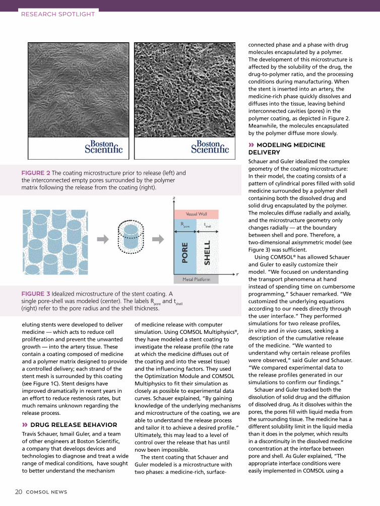
connected phase and a phase with drug molecules encapsulated by a polymer. The development of this microstructure is affected by the solubility of the drug, the drug-to-polymer ratio, and the processing conditions during manufacturing. When the stent is inserted into an artery, the medicine-rich phase quickly dissolves and diffuses into the tissue, leaving behind interconnected cavities (pores) in the polymer coating, as depicted in Figure 2. Meanwhile, the molecules encapsulated by the polymer diffuse more slowly.
» MODELING MEDICINE DELIVERYSchauer and Guler idealized the complex geometry of the coating microstructure: In their model, the coating consists of a pattern of cylindrical pores filled with solid medicine surrounded by a polymer shell containing both the dissolved drug and solid drug encapsulated by the polymer. The molecules diffuse radially and axially, and the microstructure geometry only changes radially — at the boundary between shell and pore. Therefore, a two-dimensional axisymmetric model (see Figure 3) was sufficient.
Using COMSOL® has allowed Schauer and Guler to easily customize their model. “We focused on understanding the transport phenomena at hand instead of spending time on cumbersome programming,” Schauer remarked. “We customized the underlying equations according to our needs directly through the user interface.” They performed simulations for two release profiles, in vitro and in vivo cases, seeking a description of the cumulative release of the medicine. “We wanted to understand why certain release profiles were observed,” said Guler and Schauer. “We compared experimental data to the release profiles generated in our simulations to confirm our findings.”
Schauer and Guler tracked both the dissolution of solid drug and the diffusion of dissolved drug. As it dissolves within the pores, the pores fill with liquid media from the surrounding tissue. The medicine has a different solubility limit in the liquid media than it does in the polymer, which results in a discontinuity in the dissolved medicine concentration at the interface between pore and shell. As Guler explained, “The appropriate interface conditions were easily implemented in COMSOL using a
RESEARCH SPOTLIGHT
eluting stents were developed to deliver medicine — which acts to reduce cell proliferation and prevent the unwanted growth — into the artery tissue. These contain a coating composed of medicine and a polymer matrix designed to provide a controlled delivery; each strand of the stent mesh is surrounded by this coating (see Figure 1C). Stent designs have improved dramatically in recent years in an effort to reduce restenosis rates, but much remains unknown regarding the release process.
» DRUG RELEASE BEHAVIORTravis Schauer, Ismail Guler, and a team of other engineers at Boston Scientific, a company that develops devices and technologies to diagnose and treat a wide range of medical conditions, have sought to better understand the mechanism
FIGURE 2 The coating microstructure prior to release (left) and the interconnected empty pores surrounded by the polymer matrix following the release from the coating (right).
FIGURE 3 Idealized microstructure of the stent coating. A single pore-shell was modeled (center). The labels R
pore and t
shell
(right) refer to the pore radius and the shell thickness.

COMSOL NEWS 21
stiff-spring method, which ensured the continuity of the diffusive flux.” The customizable boundary conditions available in COMSOL Multiphysics allowed Schauer and Guler to easily add the necessary terms.
Certain model parameters had to be estimated because they were "effective" values that could not be measured directly, such as the polymer shell thickness. Another was the retardation coefficient, which accounts for the twisted shape and constriction of the pores, steric effects, and other potential influences on the diffusion through the pores. These parameters were refined using the Optimization Module. Schauer and Guler made an initial guess for the shell thickness and retardation coefficient, based on experimental kinetic
FIGURE 4 Simulation results alongside experimental results showing release curves for the in vitro and in vivo cases.
FIGURE 5 Predicted medicine concentration for the in vitro case at time = 2 hours; C/C
s = dissolved drug concentration/solubility limit (left),
S/S0 = solid drug concentration/initial solid drug concentration (right).
drug release (KDR) data. They compared the model’s predicted release profile to the KDR curves. Based on the results, the Optimization Module was used to modify the shell thickness and retardation coefficient to obtain the best fit between the model results and the experimental data. The release curves (see Figure 4) confirm that the medicine in the pores releases quickly, while the dispersed molecules in the shell diffuse slowly through the encapsulating polymer. The results in Figure 5 depict the faster dissolution and diffusion in the pore, compared to the shell.
» FUTURE STENT STUDIESReducing restenosis rates is an ongoing goal for doctors and medical professionals that is greatly aided by drug-eluting stents. The modeling approach employed by Schauer and Guler offers valuable insight into one type of release mechanism. Although the simplified microstructure model does not capture all the details of the release curves, the pore-shell simulation showed good agreement, lending confidence to the appropriateness of their idealized model.
Researchers at the U.S. Food and Drug Administration (FDA) are developing even more comprehensive simulations, based on diffuse-interface theory, to examine the microstructure formation. These models aim to explain the relationship between processing, microstructure, and release behavior in controlled systems. Ultimately, simulation has the potential to give medical device designers more control over the delivery process and improve treatment for patients with cardiovascular disease.
RESEARCH SPOTLIGHT
“By gaining knowledge of the underlying mechanisms and microstructure of the coating, we are able to understand the release process and tailor it to achieve a desired profile.”
— TRAVIS SCHAUER, ENGINEER AT BOSTON SCIENTIFIC CORPORATION

22 COMSOL NEWS
MULTIPHYSICS INNOVATION
HORIBA Medical, France
OPTIMIZING HEMATOLOGY OPTIMIZING HEMATOLOGY ANALYSIS: WHEN PHYSICAL ANALYSIS: WHEN PHYSICAL PROTOTYPES FAIL, PROTOTYPES FAIL, SIMULATION PROVIDES THE SIMULATION PROVIDES THE ANSWERS ANSWERS by ALEXANDRA FOLEY
Laboratory tests, such as hematology analysis, influence up to 70 percent of critical decisions including hospital admittance, discharge, and treatment. The accuracy of these tests, therefore, is of the utmost importance to the bottom line — curing a patient’s ailment or saving a life. At HORIBA Medical, a worldwide supplier of medical diagnostic equipment, simulation software plays an important role in the research and development process, helping to ensure that these tests are as accurate and encompassing as possible.
At the center of HORIBA Medical’s cutting-edge hematology analysis equipment is a well-known approach to blood analysis that uses a combination of optical measurement and electrical impedance to analyze a sample. The impedance measurement device utilizes a micro aperture-electrode system through which blood passes (see Figure 1). Electrical impedance is then used to count the number of cells and measure the size and distribution of erythrocytes (red blood cells), platelets, and leukocytes (white blood cells). After impedance measurement, a laser and optical detector are used to sort the different types of leukocytes.
In order to take measurements that are inaccessible using just physical prototyping, HORIBA Medical turned to simulation to optimize and improve their line of leading hematology analysis equipment.
FIGURE 1 Diagram of the aperture-electrode system present in the ABX Pentra Series Analyzers.
COMSOL NEWS 23
MULTIPHYSICS INNOVATION
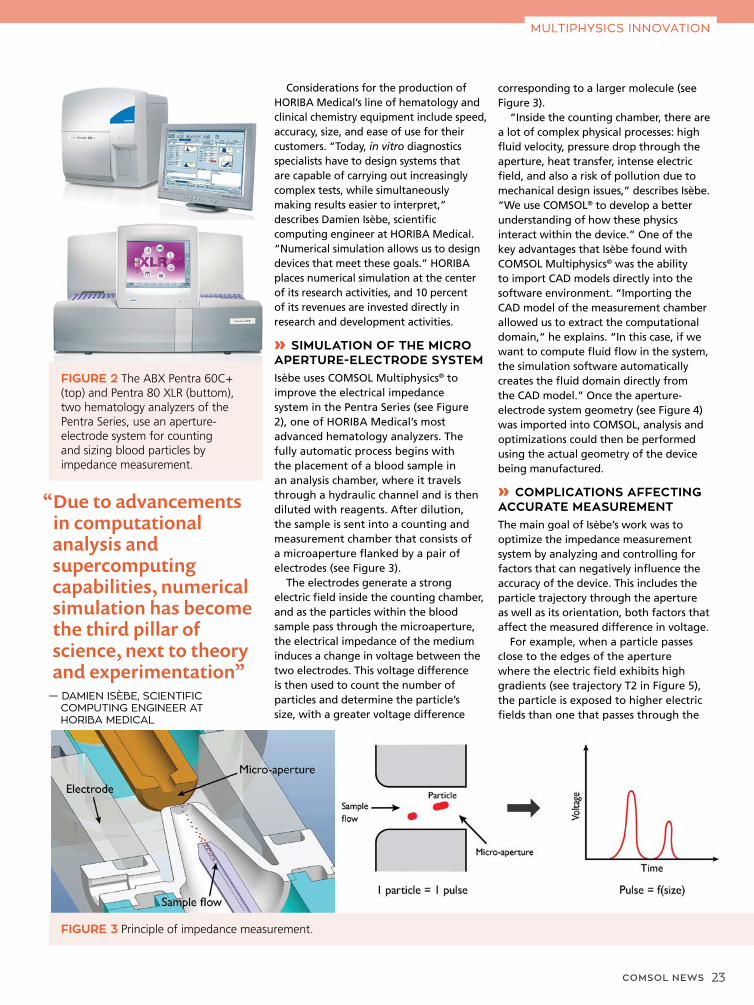
FIGURE 2 The ABX Pentra 60C+ (top) and Pentra 80 XLR (buttom), two hematology analyzers of the Pentra Series, use an aperture-electrode system for counting and sizing blood particles by impedance measurement.
FIGURE 3 Principle of impedance measurement.
Considerations for the production of HORIBA Medical’s line of hematology and clinical chemistry equipment include speed, accuracy, size, and ease of use for their customers. “Today, in vitro diagnostics specialists have to design systems that are capable of carrying out increasingly complex tests, while simultaneously making results easier to interpret,” describes Damien Isèbe, scientific computing engineer at HORIBA Medical. “Numerical simulation allows us to design devices that meet these goals.” HORIBA places numerical simulation at the center of its research activities, and 10 percent of its revenues are invested directly in research and development activities.
» SIMULATION OF THE MICRO APERTURE-ELECTRODE SYSTEMIsèbe uses COMSOL Multiphysics® to improve the electrical impedance system in the Pentra Series (see Figure 2), one of HORIBA Medical’s most advanced hematology analyzers. The fully automatic process begins with the placement of a blood sample in an analysis chamber, where it travels through a hydraulic channel and is then diluted with reagents. After dilution, the sample is sent into a counting and measurement chamber that consists of a microaperture flanked by a pair of electrodes (see Figure 3).
The electrodes generate a strong electric field inside the counting chamber, and as the particles within the blood sample pass through the microaperture, the electrical impedance of the medium induces a change in voltage between the two electrodes. This voltage difference is then used to count the number of particles and determine the particle’s size, with a greater voltage difference
corresponding to a larger molecule (see Figure 3).
“Inside the counting chamber, there are a lot of complex physical processes: high fluid velocity, pressure drop through the aperture, heat transfer, intense electric field, and also a risk of pollution due to mechanical design issues,” describes Isèbe. “We use COMSOL® to develop a better understanding of how these physics interact within the device.” One of the key advantages that Isèbe found with COMSOL Multiphysics® was the ability to import CAD models directly into the software environment. “Importing the CAD model of the measurement chamber allowed us to extract the computational domain,” he explains. “In this case, if we want to compute fluid flow in the system, the simulation software automatically creates the fluid domain directly from the CAD model.” Once the aperture-electrode system geometry (see Figure 4) was imported into COMSOL, analysis and optimizations could then be performed using the actual geometry of the device being manufactured.
» COMPLICATIONS AFFECTING ACCURATE MEASUREMENTThe main goal of Isèbe’s work was to optimize the impedance measurement system by analyzing and controlling for factors that can negatively influence the accuracy of the device. This includes the particle trajectory through the aperture as well as its orientation, both factors that affect the measured difference in voltage.
For example, when a particle passes close to the edges of the aperture where the electric field exhibits high gradients (see trajectory T2 in Figure 5), the particle is exposed to higher electric fields than one that passes through the
“Due to advancements in computational analysis and supercomputing capabilities, numerical simulation has become the third pillar of science, next to theory and experimentation”
— DAMIEN ISÈBE, SCIENTIFIC COMPUTING ENGINEER AT HORIBA MEDICAL

24 COMSOL NEWS
center of the aperture (see trajectory T1 in Figure 5). Such a phenomenon is known as edge effect. Due to this effect, the resulting electrical pulse is distorted and computation of the particle’s size results in overestimation.
This is further complicated by the particle’s orientation through the aperture. The electric field distribution changes depending on a particle that passes horizontally or vertically through the aperture, again resulting in an overestimation of the particle’s size (see Figure 6).
» A REAL IMPROVEMENT FOR DIAGNOSTIC EFFICIENCYIsèbe used simulation techniques to develop a way to account for varying particle trajectories and orientations. “Since this is a very small system, it’s
FIGURE 4 CAD model of the micro aperture-electrode system, which was imported into COMSOL Multiphysics using the CAD Import Module.
very difficult to take any measurements experimentally,” describes Isèbe. “Simulation allows us to improve processes that are inaccessible with just physical prototypes.”
Historically, counting and sizing of biological particles in an aperture-electrode system have been completed with the assumption that a sample is evenly distributed within the micro-aperture. The mean particle size was then determined statistically to compensate for errors due to particle trajectory and orientation. This compensation ignores the electrical pulses generated by the particles that pass close to the edge, but in practice it is difficult to differentiate the altered pulses from the normal ones due to the high speed of counting.
In order to improve the accuracy of the device, Isèbe developed numerical models to prove that hydrodynamic focusing could be used to reduce analysis error (see Figures 7 and 8). “Hydrodynamic focusing uses sheath flow to control the sample rate inside the aperture and to direct the sample flow along the central axis of the aperture,” says Isèbe. “The simulations of this system use a multiphysics approach that models the electrical pulses resulting from the impedance variation combined with particle fluid flow analysis.”
Isèbe ran simulations to analyze how hydrodynamic focusing improves impedance measurement, and to determine the optimal configuration
of the device. “Using these models, we can precisely compute the velocity field within the device and analyze the acceleration phase at the entrance of the microaperture. We can then use this information to determine which designs produce the most accurate results.” The simulation results demonstrated that hydrodynamic focusing greatly improves the accuracy of particle measurement (see Figure 8, top).
Next, these analyses were compared to the experimental results. “When we compared the simulation and experimental results for the two cases,
MULTIPHYSICS INNOVATION
FIGURE 5 Electric field contour plot inside the electrode-aperture. Two possible particle trajectories, T1 and T2, are shown.
“Since this is a very small system, it is very difficult to take any measurements experimentally. Simulation allows us to improve processes that are inaccessible with just physical prototypes.”
— DAMIEN ISÈBE, SCIENTIFIC COMPUTING ENGINEER AT HORIBA MEDICAL

COMSOL NEWS 25
FIGURE 6 Effect of particle orientation on the electric field distribution within the electrode-aperture system and the resulting difference in voltage.
FIGURE 7 Hydrodynamic focusing simulation, showing how sheath flow is used to direct the sample along the central axis of the electrode aperture (sample flow in red and sheath flow in blue).
FIGURE 8 Top: Simulation results of the static particle size distribution without hydrofocusing (left) and with hydrofocusing (right). Bottom: Experimental validation without hydrofocusing (left) and with hydrofocusing (right).
we estimated that the hydrofocused device is about twice as accurate as the nonhydrofocused one,” explains Isèbe, referring to Figure 8, bottom.
» SIMULATION JUSTIFIES TECHNOLOGICAL INNOVATIONThe design and optimization of this system of electrical impedance measurement for hematology analysis was truly a multiphysics application, involving the coupling of mechanical, fluid, chemical, and electrical analyses. The resulting devices, the ABX Pentra Series, are among the most accurate fully automatic analyzers on the market today. “Using simulation, I was able to justify the implementation of this technique for hematology analysis into the diagnostic equipment at HORIBA,” says Isèbe. Currently, Isèbe is working on improvements to the particle fluid flow analysis, and plans for future research include 3D processing and the deformability of particles under hydrodynamic stresses. “Due to advancements in computational analysis and supercomputing capabilities, numerical simulation has become the third pillar of science, next to theory and experimentation,” says Isèbe. “Simulation is now a critical tool for research and development at HORIBA Medical, and it is a key resource used for decision-making in technological innovation.”
MULTIPHYSICS INNOVATION

26 COMSOL NEWS
If the two systems could be combined, they would form an ideal treatment system that could pinpoint any tumor at all times during treatment, in particular, tumors within the thorax or abdomen that move with breathing. This has, until recent years, been regarded as an impossible undertaking. Now, a team based at the Cross Cancer Institute in Edmonton, Canada, has proved that it is not.
» ONE CHALLENGE AFTER ANOTHER Professor Gina Fallone of the University of Alberta, also in Edmonton, established a task force to attack the problem in 2005. Since then, he and his team have been knocking down barriers previously regarded as insurmountable. They achieved proof of concept in 2008 when they built a fully operational prototype designed for the head (see Figure 1).
“It would be difficult to overstate the different engineering and physics issues within the Linac-MR Project,” Fallone says. “We have had to consider the design of the MRI system, the Linac; the optimal combination of both; and the room in which the new installation would be housed.” Simulation plays a vital role in the progression toward clinical use of real-time, MRI-guided radiation, and team members have been using COMSOL Multiphysics® since 2006.
“One of the earliest projects we did with a magnetostatics simulation was to establish a means of shielding the Linac from the MRI’s magnetic fields,” says team member Stephen
MULTIPHYSICS INNOVATION
A rather unpalatable truth is that the targeting of radiation therapy for cancer involves significant uncertainty in accurately targeting tumors. On the other hand, magnetic resonance imaging (MRI) may be used to help by accurately identifying the location of a tumor in soft tissue, but it has to be carried out totally independently of radiation treatment delivered by a linear particle accelerator (Linac) because the two techniques conflict.
MRI scanners need to receive extremely faint radio frequency (RF) signals from the patient to produce an image. The electrical needs of the Linac produce very large RF signals, however, that interferes with the process of collecting faint signals. On the other hand, electrons from the Linac need to be directed precisely onto a target to produce cancer-killing X-rays, but the stray magnetic fields from the MRI deflect the electrons, impairing the Linac’s function.
FIGURE 1 Configuration of the Linac-MR system.
University of Alberta/Cross Cancer Institute, AB, Canada
MRI TUMOR-MRI TUMOR-TRACKED TRACKED
CANCER CANCER TREATMENT TREATMENT
by JENNIFER HAND
In a project that is truly breaking the boundaries of what was thought possible, a team from the Cross Cancer Institute in Canada is combining the superb quality of magnetic resonance imaging with the power of a linear particle accelerator to enable ultraprecise radiation therapy.

COMSOL NEWS 27
of major importance because it means that the room we are constructing to take the Linac MR can be significantly smaller.” COMSOL Multiphysics was also used to establish whether this special room needed to be magnetically shielded (see Figure 3). The results showed that it did, and further simulations determined the thickness of the special steel lining.
The first wholebody Linac MR is being constructed inside this room.
» TIGHT TARGETING The prototype is being used for fundamental research on the engineering of the system’s critical component, and the team is now preparing the documentation required to seek government approval for a Linac MR to be used as an investigational device for humans in clinical trials.
“COMSOL Multiphysics is an extremely practical and helpful tool, which is enabling us in this important work,” says Fallone. “Cancer patients currently have to undergo irradiation of the whole area around a tumor and some internal organs are particularly difficult to treat because they are so difficult to see. The Linac MR is set to transform radiation therapy.”
MULTIPHYSICS INNOVATION
Steciw, an associate professor at the University of Alberta. “Having resolved that problem, we moved on to other issues, such as simulating and optimizing the structure of the MRI scanner, which has to incorporate a hole for the beam of X-rays to pass through. We had previously investigated the impact on the image quality when a Linac rotates around an MRI. We therefore studied angle-specific field heterogeneities and different ways to circumvent these. We verified that designing the Linac and the scanner to move together as one whole system resolved this issue.”
» PROTECTING THE LINACWith regard to shielding the Linac, the initial aim was to shield down to 0.5 Gauss, the magnitude of Earth’s magnetic field. To accomplish this, the steel plate of the shielding wall was initially set at a thickness of 5 centimeters and a dimension of 200 cm by 200 cm. Joel St. Aubin, a former medical physics PhD graduate student who worked on the project, picks up the story.
“Using COMSOL Multiphysics, we were able to verify the tolerances of the Linac to the magnetic field and reduce the shield
to a radius of 30 cm with a thickness of 6 cm. The new shield was more than three times lighter than the original, much more practical from an engineering design point of view. This new shield also dramatically reduced the MRI’s field inhomogeneities — by more than three times — which is important for producing a distortion-free MRI image.”
In addition to the passive shielding of the Linac, the team also investigated active shielding, running an electromagnetics simulation of a counter magnetic field.
» HIGH ENERGY WITH A SHORT WAVEGUIDE“We wanted the Linac MR to generate a 10-megaelectronvolt (MeV) electron beam,” explains Steciw (see Figure 2). “Given current sizing options, that would have meant buying a waveguide that was actually capable of generating 22-MeV electrons and measured 150 cm, too much and too long for our needs. We estimated that we needed 70 cm in length, but by using COMSOL Multiphysics, we found out that we could take the waveguide right down to 30 cm. Now we are designing a new S-band waveguide.
This reduction in length is
FIGURE 2 Cutaway view (left) and electric field distribution (right) of the short 10-MeV waveguide.
FIGURE 3 Passive shielding for a perpendicular Linac MR orientation (magnetic field lines perpendicular to electron trajectories).

28 COMSOL NEWS
RESEARCH SPOTLIGHT
Presbyopia is a natural effect of aging in which a loss of elasticity in the lens of the eye causes far-sightedness. As a result, your visual accommodation gradually declines, as your eyes can no longer effectively change their optical power to maintain a clear image or focus on an object as its distance varies.
The current solutions to this problem are at opposite ends of the treatment spectrum: You can either wear a pair of glasses or opt for an invasive surgical solution that could compromise the quality of your vision (Figure 1).
A novel solution developed by medical device company Kejako will provide a viable treatment that treads the middle ground between surgery and spectacles. Their 3D parametric full-eye model is providing invaluable insights into the root cause of the eye’s degeneration over time. As a result, Kejako is edging closer to an innovative solution that will delay the need for reading glasses or invasive surgery for more than 20 years.
» PERSONALIZED TREATMENT OPTIONSKejako’s cofounder and CEO, David Enfrun, explained: “Our solution has the potential to become the next generation’s standard of care in personalized ophthalmic antiaging medicine,” explained David Enfrun, Kejako’s cofounder and CEO. We focus on early treatments to maintain enough capacity of visual accommodation by offering personalized antiaging laser treatments that could give patients an additional 20 years of comfortable vision.”
Kejako’s solution is designed to treat the root causes of presbyopia and features a series of noninvasive laser eye surgeries, which are prescribed from when a patient starts to develop presbyopia until cataracts develop. This keeps a patient’s visual accommodation amplitude above where spectacles are required (Figure 2).
To correct presbyopia, the team is combining the noninvasive treatment with simulation to provide an all-in-one solution called phakorestoration.
Kejako, Switzerland
3D PARAMETRIC 3D PARAMETRIC FULL EYE MODEL FULL EYE MODEL GIVES 20+ YEARS GIVES 20+ YEARS
OF BETTER VISIONOF BETTER VISIONA research team at Kejako, a medical device company based in Switzerland, share how they are using multiphysics simulation to develop an innovative solution that will delay the need for reading glasses or invasive surgery for decades.
by GEMMA CHURCH
FIGURE 1 Current surgical solutions result in visual compromises, including halos (top), glare (center), and poor acuity in dim light (bottom).

COMSOL NEWS 29
Their simulation work features a 3D parametric full-eye model, which the company developed using multiphysics simulation. Enfrun said: “We began our development work in 2015 with an alternative software that we were familiar with.
However, it soon became clear that this solution was too restrictive. Our project is quintessentially multiphysics.”
“In 2016, we started to work with COMSOL® because of the multiphysics nature of the software and the high quality of customer support.”
The full-eye model has the potential to provide a personalized treatment for every patient. This is important because every patient is different in terms of their physiology and the severity of their presbyopia. Enfrun explained: “One size will not fit all when treating presbyopia, and our model will be fundamental to addressing that issue. We can use the model to optimize each patient’s treatment and provide a personalized procedure.”
» EYEING THE PHYSICSTo create an accurate 3D parametric model of the eye, a full description of this organ must be taken into account and several physics phenomena be considered. Aurélien Maurer, R&D engineer at Kejako and eye model project leader, explained: “We needed a complete solution, including the mechanics and optics of the eye. We wanted to model the entire eye and adapt its properties to look at different outcomes.”
A range of complex physics must be considered to achieve this. Within the eye, there are a lot of different physics and material properties to take into consideration, such as the fluidics of the aqueous humor; optical behavior of the lens and cornea material; and the refractive index, which involves modeling the muscle ligaments as they deform the lens.
The team also wanted to model the gradient of the refractive index as light penetrates the crystalline lens, so they coupled structural mechanics and ray optics. Maurer said: “No one before had looked at the relation between the mechanical deformation and the refractive index gradient in the crystalline lens, so we decided to put this in a model and test it against the existing results in the literature.”
The team’s dual approach of modeling both the mechanical and optical elements of the eye was validated using existing measurements. “If we only model the mechanics or the optics, then we do not get all the information we need. But if we put all of this together,
FIGURE 2 Principle of phakorestoration’s action on visual accommodation as a function of age.
FIGURE 3 Various components of the eye that needed to be taken into consideration for the multiphysics model.
“We started to work with COMSOL® because of the multiphysics nature of the software and the high quality of customer support. "
— DAVID ENFRUN, COFOUNDER AND CEO, KEJAKO
RESEARCH SPOTLIGHT

30 COMSOL NEWS
that is where the magic happens,” Maurer added.
» MULTIPHYSICS FOCUSUsing geometries from statistical measurements and standard optical coherence tomography (OCT) imaging techniques, the team began to develop their model by imaging the eye and then translating this information into a parameterized 3D geometry imported in the COMSOL software.
The mechanical elements of the eye were then modeled, including the
complex muscle ligaments that pull the lens into shape and the viscoelastic properties of the vitreous fluid that fills the eye.
The fibrous nonhomogeneous nature of the sclera was also modeled. Charles-Olivier Zuber, a biomedical PhD student at Kejako and Rostock University, Germany, explained: “The sclera is the white part of the eye and it is made of collagen fibers. Because those fibers are made of collagen, we needed to examine their nonlinear mechanical properties in a multiphysics environment.” The
FIGURE 4 From measurement to simulation. Left: A typical eye imaging from an OCT. Middle: A cross section of the 3D model based on the measurement from the OCT results, created using the SOLIDWORKS® software. Right: Mesh of the 3D model created using COMSOL Multiphysics®.
FIGURE 5 Left: Simulation results showing eye deformation and ray tracing in far vision. Right: Ray focusing after traveling through the eye optical system. Dark colors represent higher ray density.
displacement of the eye material for a specified accommodation relative to the resting state can be determined by taking all of the elements into account (Figure 5, left).
The ray optics capabilities of the software were used to trace the light rays, modeling the refractive properties of the lens and ray focusing on the retina, considering parallel incoming rays
FIGURE 6 Simplified finite multilayer representation of the GRIN with decomposition in equivalent lens. Far vision is pictured on the left, near vision on the right. Colors represent the value of the refractive index with the highest values in red.
RESEARCH SPOTLIGHT

COMSOL NEWS 31
(as if they were emitted by an infinitely far source). This enabled simulations of the patient’s sharpness of vision and the objective amplitude of accommodation to be determined. Ray focusing of the eye optical system (cornea and crystalline lens) can be simulated (Figure 5, right). How rays distribute on the retina depends on individual visual acuity. “We can provide models that produce exactly what the patient sees, enabling us to better understand and treat presbyopia. For example, we can see how the image forms on the retina for each individual, so sharpness of vision can be addressed,” Maurer added. The team validated its visual accommodation analysis and the presbyopia simulation using measurements from more than 50 eyes.
The ability to model this vast range of parameters was key to the creation and success of the 3D parametric full-eye model. Zuber, explained: “What we appreciate about COMSOL is that we have access to all of these parameters driving the geometric configuration, material properties, and physics involved. Such flexibility is very helpful to improve our comprehension of the problem and find the most effective solution.”
» GIVE US A GRINMultiphysics simulation allowed the team to deduce some of the nonmeasurable mechanical properties of the lens, including the gradient of refractive index (GRIN) used in the 3D parametric model of the eye. The refractive index of the human eye lens has subtle fluctuations and this creates a particular reflectance pattern. The GRIN
consists of spatial continuous variation of the refractive index over the lens, which increases from the surface to the center. This repartition has a strong influence on focalization of light, aberration, and thus visual acuity. Through simulation, the GRIN of the eye lens can be calculated, which is vital to understanding how light passes through the structure.
The GRIN acts as a multiplicative factor for the visual accommodation of the eye. As the lens tissues (with their specific refractive index) move with the lens accommodation, it results in two different optical configurations for each extreme state, either far or near vision (Figure 6).
The lens is made of fiber-shaped cells arranged in concentric layers like an onion. This organization is responsible for the lens transparency, but this also has a strong influence on its anisotropic mechanical properties. The model accounts for this microstructure, using the curvilinear coordinate feature available in the software to represent the fiber arrangement (Figure 7). The GRIN value is incredibly difficult to measure directly, but its incorporation into the team’s parametric model (Figure 8) was vital to ensure the accuracy of the model and, subsequently, the effectiveness of any proposed treatment.
» SIMULATION FOR ALLThe team is now building simulation apps using the Application Builder available in the software to extend the reach of its 3D parametric full-eye model and prepare the company for market maturity.
Once the multiphysics model is packaged into a simulation app with
FIGURE 7 Curvilinear coordinate system used to represent the anisotropic material properties of the lens. The GRIN distribution is shown.
FIGURE 8 Left: Example of a GRIN measured with magnetic resonance imaging (MRI). Right: Parametric model of the GRIN.
an easy-to-use interface, Kejako’s work is ready for a clinical setting through a straightforward process. A clinician can use standard OCT imaging to image the patient’s eye. This information is sent to Kejako, where the team of experts can create a personalized 3D parametric full-eye model. This model is then further optimized and a customized phakorestoration procedure is created.
The projected prevalence of presbyopia is predicted to reach more than 1.3 billion people by 2020, so apps will be fundamental to keep up with the demand, as nonexperts in simulation can benefit from multiphysics to create each patient’s phakorestoration treatment.
“Simulation and modeling have allowed for time savings with regards to our in vivo and ex vivo tests. We will move to trial when we are confident that we can do something significant in the human body and are convinced of our solution, and COMSOL Multiphysics® will help us to achieve that in a much shorter time frame,” Enfrun added.
“If we only model the mechanics or the optics, then we do not get all the information we need. But if we put all of this together, that’s where the magic happens.”
— AURÉLIEN MAURER, R&D ENGINEER, KEJAKO
RESEARCH SPOTLIGHT

32 COMSOL NEWS
MULTIPHYSICS INNOVATION
STMicroelectronics, Italy
RELIABLE STRUCTURES RELIABLE STRUCTURES AND WEARABLE SYSTEMS AND WEARABLE SYSTEMS CALL FOR MULTIPHYSICS CALL FOR MULTIPHYSICS SIMULATION SIMULATION by COMSOL
FIGURE 1 Technique used to measure the bioimpedance of an organ.
The increasing demand for miniaturized electronics and internet of things (IoT) devices has created new challenges for the specialists who design microdevices such as actuators, controllers, drivers, sensors, and transmitters. From responsive equipment and wearable monitors to energy-efficient lighting in the office and automation in the factory, engineers need to bridge the microscopic components of semiconductors and our macroscopic world with reliable and innovative products. This shift has inspired engineers to find new solutions by exploring their ideas in the virtual world of numerical simulation.
STMicroelectronics, a world leader in designing and manufacturing semiconductor solutions, employs 7500 individuals in the area of research and development (R&D). Lucia Zullino, technology R&D engineer at STMicroelectronics, explains their efforts. “In our field, we need to analyze very small structures and understand their interaction with large packages in different configurations over a wide range of environments and applications.”
For semiconductor manufacturers, the choice of material and design is critical. This is where simulation plays an important role in the evaluation of materials and performance parameters. “Much of our work is done through the COMSOL Multiphysics® software, which we use to validate hypotheses and to optimize products,” explains Zullino. “There are about 30 users within STMicroelectronics, and although we belong to different departments and work in various locations, we are continually building and sharing knowledge about mathematical modeling techniques used in several projects.”
» MULTIPHYSICS SIMULATION FOR RESEARCH AND PRODUCT DESIGNSimulation is used to understand multiphysics interactions at every stage of the development process for several products. A few examples include: optimizing an epitaxial reactor for faster wafer production, controlling reactant flow distortion in the wet etching process, and investigating the interaction between die and package
Engineers at STMicroelectronics use numerical simulation to optimize their semiconductor solutions for a wide range of applications.

COMSOL NEWS 33
at the microscopic level. In addition to design and manufacturing of microchips, engineers at STMicroelectronics work on the design of miniaturized actuators such as micromirrors used in recognition technologies that require optics and cameras. Simulation was also used in another actuator-related project to investigate printheads and compare the effectiveness of two different working principles: displacement of ink through pressure-generated bubbles or using a membrane actuated by a PZT, a ceramic material made of lead zirconate titanate. Through this work, the researchers were able to determine that the thin-film piezo printhead offers better compatibility with a wide variety of inks, higher printing speed, superior print output quality, and extended printhead lifetime.
» WEARABLE MEDICAL MONITORINGOver the years, STMicroelectronics has developed many healthcare applications. In one prototype project, a patch was designed to measure the bioimpedance of an organ, such as the heart, inside the human body (Figure 1). Working from medical imaging of human organs, researchers created a 3D model (Figure 2) to run an AC/DC simulation in the frequency domain (Figure 3) and assess the effect of the electrode shape and position on the measured physiological parameters. The simulation results they obtained (Figure 4) correlated closely with real-life measurements and enabled the development of a wearable configurable patch capable of indicating physiological changes. These sensors will enable doctors monitoring various heart conditions to get real-time data to provide patients with the best care using the latest technology.
» TACKLING MORE AND MORE COMPLEXITY THANKS TO SIMULATION“Through simulation, we have learned a lot about potential problems and we have gotten better at optimizing semiconductors for the outside world. Simulation now drives product design, both for internal and external customers,” comments Zullino. She and her colleagues see opportunities to continue using multiphysics simulation in all aspects of development. She shared that studies on humidity inside packaging and the potential for corrosion are already in progress.
“We can assess materials and structures more quickly and screen for the best ones, which means less time spent on trials, better technical decisions, and quicker business decisions,” concludes Zullino. “Compared to physical testing, we can implement new solutions and verify them at zero cost. Simulation is one of the key tools that drives innovation.”
FIGURE 2 3D model created from computed tomography (CT) images (top), postprocessed with CAD tools (middle), and then interpolated to generate the volumes (bottom) needed for the analysis.
FIGURE 3 Simulation results showing the electric voltage and current distribution in a human torso.
FIGURE 4 Comparison between measured and simulated bioimpedance values (top) for different electrode shapes and positions (bottom).
MULTIPHYSICS INNOVATION

34 COMSOL NEWS
The University of Oklahoma College of Pharmacy, OK, USA
ADDING QUANTITATIVE ADDING QUANTITATIVE SYSTEMS PHARMACOLOGY SYSTEMS PHARMACOLOGY TO THE PHARMACEUTICAL TO THE PHARMACEUTICAL SCIENCES CURRICULUM SCIENCES CURRICULUM
by BRIDGET PAULUS
SIMULATION IN THE CLASSROOM
The University of Oklahoma College of Pharmacy is teaching PhD students in pharmaceutical sciences how to create multiscale models in order to analyze drug disposition within the human body.
Optimizing drug dosages, evaluating side effects, improving clinical trials, and reducing costs and time to market — these are just a few of the benefits of model-informed drug development. Due to these advantages, the United States Food and Drug Administration (FDA) is encouraging pharmaceutical companies to include simulation in their product development cycles. There is just one problem: Companies often have a hard time finding candidates with strong experience in simulation, as mathematical modeling is minimal in most pharmaceutical sciences programs.
To address this issue, the Institute of Quantitative Systems Pharmacology and the College of Pharmacy at the University of Oklahoma Health Sciences Center partnered in 2014 to develop an innovative curriculum. Within this program, Research Assistant Professor Roberto A. Abbiati designed a PhD-level course on simulation for pharmaceutical sciences students at the University of Oklahoma College of Pharmacy. The class gives an overview of numerical analysis and the modeling workflow in the COMSOL Multiphysics® software. Students learn how to apply modeling to pharmacokinetics, the branch of pharmacology that studies the effect of the human body on the administered drugs. Specifically, Abbiati applies modeling to streamline the quantification of drug concentration levels in the human body and the intended target sites over time — an important concern when developing potentially life-saving treatments.
» TEACHING MODELING TO THE NEXT GENERATION OF PHARMACEUTICAL SCIENTISTSPharmaceutical sciences students learn about a wide variety of subjects, but simulation is not typically one of them. According to Abbiati, this is a problem: "Besides being a desired skill by companies, modeling and simulation help design better experiments," he says.
Abbiati's courses are designed to teach PhD students in pharmaceutical sciences how to take advantage of simulation software in their work. The course starts students off with the MATLAB® software, which serves as a bridge to other kinds of mathematical modeling software. As the course continues, Abbiati and his students delve into numerical analysis and the finite element method.
Eventually, students learn how to build models in COMSOL Multiphysics. Abbiati takes them through each step of the modeling workflow. Students learn how to build geometries (starting in 2D, like the laminar flow example in Figure 1); set up the physics; determine the best mesh for a model (Figure 2); and postprocess the results (Figure 3).
Throughout the course, the class learns how to create both compartmental and multiscale models. The former is the standard for pharmacokinetic applications and is an easier concept to understand. Abbiati says that a standard compartmental model "assumes the human body is like a box, with one flux in and one flux out." Using ordinary differential equations, compartmental
MATLAB is a registered trademark of The MathWorks, Inc.

COMSOL NEWS 35
FIGURE 1 Velocity map for laminar fluid flow in a channel.
the fluid carries the drug with it. He then used the Transport of Diluted Species interface to describe the drug concentration.
Abbiati said that he was able to use this model "to determine how deep the drug penetrates the tumor, depending on changes in its physical structure over time" (Figure 4). The advantage of using multiphysics analysis was that he could "describe where the drug is located at any given time and any given location of the tumor." From his research, it is clear that multiscale modeling is a useful
tool for pharmacokinetics, enabling researchers to better understand how drug concentrations are affected by the human body.
By teaching simulation in his PhD-level pharmaceutical sciences courses, Abbiati is giving students a valuable skill for drug research that could greatly improve future drug development processes. Aside from that, because these students will graduate with a simulation background, they are more attractive to pharmaceutical companies when they are ready to enter the workforce.
modeling is a simple way to determine the drug concentration in the human body over time. There is a major limitation with this type of model, though. Abbiati says, "It cannot determine where the drug is localized within specific tissues, which is a critical limitation in several applications, including cancer treatment."
Enter multiscale modeling. While it requires a more detailed understanding of physiological and biological processes compared to compartmental modeling, multiscale modeling is able to provide valuable insight into how deep a drug can penetrate a certain tissue or organ. This type of simulation involves accounting for size scales ranging from the entire human body, individual organs, single cells, down to the molecular level. Although it sounds like a complex subject, Abbiati demonstrates a step-by-step approach that is easier for the students to learn.
» GAINING INSIGHT INTO TUMOR TREATMENTDr. Abbiati highlighted the benefits of multiscale modeling for pharmacokinetics by sharing some of his own research performed with his team at the Institute of Quantitative Systems Pharmacology. He is currently studying how drugs interact with solid tumors. These drugs, which typically travel via the bloodstream, can have a hard time getting into tumors. The issue is that these types of masses have "physical barriers that limit drug delivery," explained Abbiati. Tumor sites often have high pressure, which makes it difficult for the drug to penetrate them, for instance.
"I'm using COMSOL® to understand why and how the physical structure of the tumor is a barrier for the delivery of the drug," says Abbiati. To gain such insight, he uses multiphysics simulation to model blood flow in microvascular vessels, drug transport within the tumor interstitial space, and drug interaction with tumor cells. Abbiati modeled how the fluid moves according to the pressure gradient within a tumor mass, assuming that
FIGURE 2 Mesh comparison used to introduce students to various mesh options.
FIGURE 3 Velocity pattern for laminar fluid flow in a channel with obstacles of different sizes, an example from Abbiati's course.
FIGURE 4 The drug concentration profile in a tumor.
SIMULATION IN THE CLASSROOM
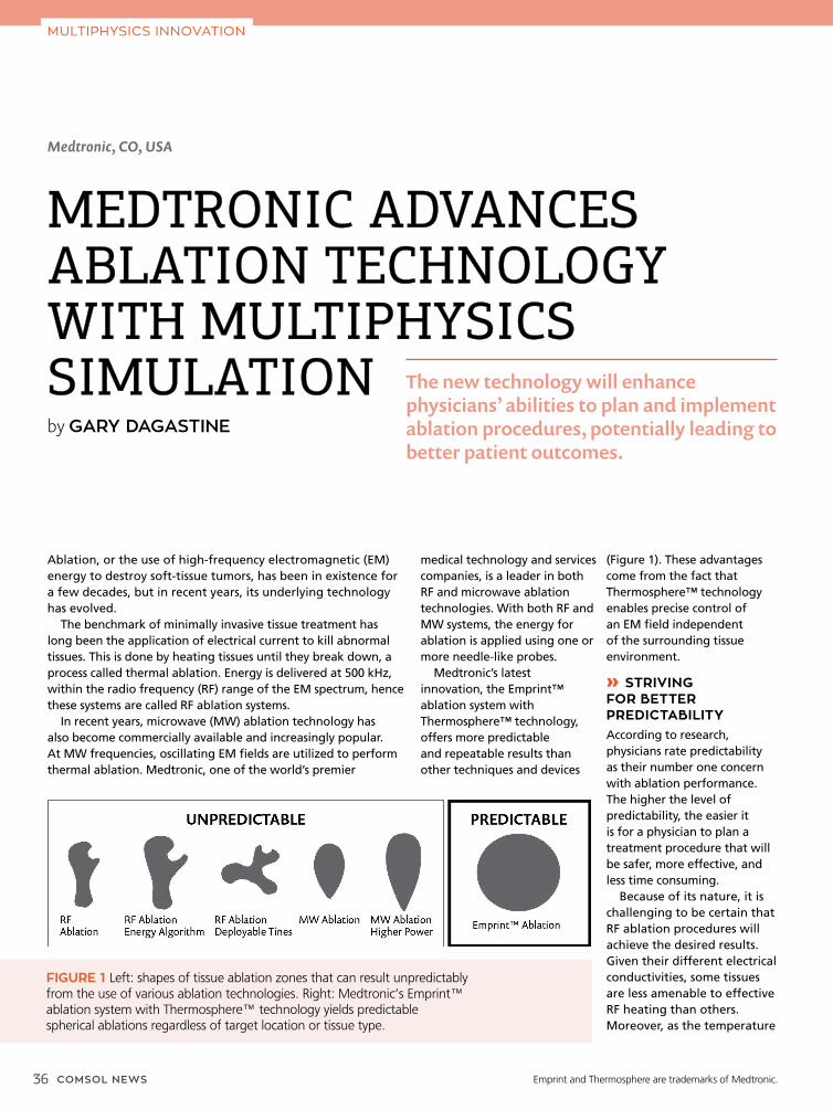
36 COMSOL NEWS
MULTIPHYSICS INNOVATION
Medtronic, CO, USA
MEDTRONIC ADVANCES MEDTRONIC ADVANCES ABLATION TECHNOLOGY ABLATION TECHNOLOGY WITH MULTIPHYSICS WITH MULTIPHYSICS SIMULATION SIMULATION by GARY DAGASTINE
Ablation, or the use of high-frequency electromagnetic (EM) energy to destroy soft-tissue tumors, has been in existence for a few decades, but in recent years, its underlying technology has evolved.
The benchmark of minimally invasive tissue treatment has long been the application of electrical current to kill abnormal tissues. This is done by heating tissues until they break down, a process called thermal ablation. Energy is delivered at 500 kHz, within the radio frequency (RF) range of the EM spectrum, hence these systems are called RF ablation systems.
In recent years, microwave (MW) ablation technology has also become commercially available and increasingly popular. At MW frequencies, oscillating EM fields are utilized to perform thermal ablation. Medtronic, one of the world’s premier
medical technology and services companies, is a leader in both RF and microwave ablation technologies. With both RF and MW systems, the energy for ablation is applied using one or more needle-like probes.
Medtronic’s latest innovation, the Emprint™ ablation system with Thermosphere™ technology, offers more predictable and repeatable results than other techniques and devices
(Figure 1). These advantages come from the fact that Thermosphere™ technology enables precise control of an EM field independent of the surrounding tissue environment.
» STRIVING FOR BETTER PREDICTABILITYAccording to research, physicians rate predictability as their number one concern with ablation performance. The higher the level of predictability, the easier it is for a physician to plan a treatment procedure that will be safer, more effective, and less time consuming.
Because of its nature, it is challenging to be certain that RF ablation procedures will achieve the desired results. Given their different electrical conductivities, some tissues are less amenable to effective RF heating than others. Moreover, as the temperature
The new technology will enhance physicians’ abilities to plan and implement ablation procedures, potentially leading to better patient outcomes.
FIGURE 1 Left: shapes of tissue ablation zones that can result unpredictably from the use of various ablation technologies. Right: Medtronic’s Emprint™ ablation system with Thermosphere™ technology yields predictable spherical ablations regardless of target location or tissue type.
Emprint and Thermosphere are trademarks of Medtronic.

COMSOL NEWS 37
in targeted tissue approaches 100°C, water in the tissue begins to vaporize and electrical conductivity rapidly decreases. This can make it difficult to generate temperatures high enough to cause cell breakdown.
MW ablation technology attempts to overcome these limitations by using an EM field radiated into the tissue (Figure 2). However, in practical application, tissue type and the vaporization of water during ablation cause the size and shape of the EM field to vary.
The Emprint™ ablation system with Thermosphere™ technology realizes the promise of predictability. It gives physicians the ability to easily control the thermal energy delivered by allowing precise control of the EM field across tissues and temperatures. This allows clinicians to accurately predict the boundaries and characteristics of the ablation zone.
» REAL-TIME MONITORING OF ABLATIONS“The challenge now is to monitor the ablation performance in real-time,” said Casey Ladtkow, principal engineer in the Early Technologies unit of Medtronic’s Minimally Invasive Therapies Group (MITG). “At present, when performing ablations, physicians don’t have continuous real-time feedback
FIGURE 2 The photo at left illustrates placement of an ablation probe. The green circle delineates the target (where the lesion is located) and the red circle delineates the margin the ablation is meant to achieve. The image at right shows the site after ablation has taken place.
FIGURE 3 These results show the power dissipation density, or the extent of the ablation, as determined by the thermal damage calculation. The antenna and the surrounding tissue are initially well matched, and the match (i.e., the antenna pattern) changes over time as tissue temperature increases during the procedure (left to right).
FIGURE 4 A plot shows a cross section of the predicted ablation volume, or predicted tissue damage. This information is used to modify the bioheat equation and thereby to modify perfusion conditions in the tissue. Red areas represent coagulated tissue where no perfusion is present, and white areas represent areas of normal perfusion. This makes the model more accurate by creating a realistic on/off condition for the perfusion term in the bioheat equation.
on the effectiveness of their procedure. If they could know exactly what is happening in real-time from start to finish, the effectiveness of ablation treatment would increase,” he said.
With some 40 staff members focused on interventional oncology, the mission of his unit is to deliver procedural solutions that alleviate pain, restore health, and extend life. He and his team are using the COMSOL Multiphysics® software to develop new ablation probes in order to achieve even higher levels of predictable performance and effectiveness.
One development-stage project is to optimize the design of these probes so they can create both a more precise ablation zone and provide real-time feedback using radiometers.
Radiometers measure EM radiation and enable the characterization of the spatial distribution of an EM field. Ladtkow’s team is incorporating radiometers into Medtronic probes in order to give clinicians real-time feedback about the ablation zone. This will enable a clinician to fine tune the zone as needed during the procedure and to make sure the radiation destroys the targeted tissues while minimizing effects on the surrounding healthy tissue.
The team uses COMSOL Multiphysics and its RF Module to help them model the probes and better understand and optimize their emitting/radiating and receiving/monitoring properties. “The performance and accuracy of MW ablation systems are affected by a number of dynamic factors that arise simultaneously in multiple physics domains. The COMSOL® software gives
us the ability to perform the relevant complex modeling quickly and easily, to help us understand these coupled effects and improve our design,” Ladtkow said.
» SIMULATION ENABLES FAST AND SAFE DESIGN, OPTIMIZATION, AND PROTOTYPINGFor such a complex device, the traditional approach of building and evaluating a series of physical prototypes is all but out of the question because of the complexity and relationships among the many physics-based factors that impact device performance.
The team modeled the energy radiator and test designs that incorporated radiometric sensing in the same device. They simulated coupled thermal and
MULTIPHYSICS INNOVATION

38 COMSOL NEWS
electromagnetic effects around the radiative probe hardware to determine radiometric performance under different conditions (Figure 3).
Ladtkow analyzed heat transfer in living tissue using a bioheat equation, which included a perfusion term, to account for blood flow cessation once the tissue coagulated (Figure 4). This helped his team understand heat transport to cells around the tumor and predict the temperature distribution to ensure efficient and predictable energy delivery.
He performed other studies as well: investigations of temperature dependence of reaction rates (to understand the size of the ablation zone), radiometry modeling to determine how much energy enters the tissue and how much is reflected back into the radiator, and liquid-to-
gas phase-change dynamics (Figure 5). “The latter is critical to knowing what the wave pattern will look like, because knowing how much water is in the tissue is critical to knowing how a radiometer will behave, because of the change in wavelength,” he said. “Implementing this model in COMSOL is straightforward.”
Simulation showed that lengthening the proximal radiating section (PRS) and shortening the distal radiating section (DRS) of an antenna would produce an efficient ablation radiator and an efficient receiver. These studies (Figure 6) resulted in versions of a prototype ablation radiator with an integrated radiometer, along with results showing the performance of the integrated probe.
» FROM IMPOSSIBLE TO POSSIBLE“Without COMSOL to help us perform these analyses, it simply would be impossible to do enough experiments to find an optimum solution that integrates an emitter and a receiver. COMSOL helps us see that certain architectures — which we would never have investigated otherwise — might make an integrated device possible,” Ladtkow continued.
His team uses the COMSOL® software in conjunction with the MATLAB® software, and he said that the combination gives him a powerful ability to optimize complex models with highly sophisticated algorithms quickly and easily. He also hopes to integrate the Application Builder available in COMSOL Multiphysics into their modeling workflow. This would enable the team to create simulation apps allowing partners to test and verify different designs, while protecting their proprietary models.
FIGURE 5 Simulation results show the change in heat capacity in the tissue surrounding the probe, dominated by phase change of water in that tissue. Knowing where water is boiling is important because the MW radiation wavelength is dramatically different for liquid water than for vaporized water.
FIGURE 6 A weighted error plot. Blue areas indicate regions where reflected power is low for delivered ablation energy and also where the receiver quality is good. They represent antenna configurations that are both good ablation devices and good radiometers.
From left: The Medtronic team consists of Morgan Hill, Casey Ladtkow, and Robert Behnke.
“Based on our simulations, we are now realizing the potential to introduce ablation devices that will allow clinicians to not only deliver a precise energy dose, but also monitor ablations in real time,” Ladtkow said. “Multiphysics simulation enabled the rapid development, evaluation, and optimization of our design, which would not have been possible otherwise.”
MULTIPHYSICS INNOVATION
“Multiphysics simulation enabled the rapid development, evaluation, and opti mization of our design, which would not have been possible otherwise.”
— CASEY LADTKOW, PRINCIPAL ENGINEER, MEDTRONIC
MATLAB is a registered trademark of The MathWorks, Inc.

COMSOL NEWS 39
TREATMENT METHODS
• Analyzing HIFU Propagation Through a Tissue Phantom
• Taking a Look at Electrochemical Treatment for Tumors via Modeling
• Improving Vascular Access for the Treatment of ESRD Patients
PHYSIOLOGY SIMULATION
• Modeling Fluid-Structure Interaction in a Heart Valve
• New FEM Book Offers Modeling Guidance for Biomedical Applications
• Analyzing the Mechanical Behavior of Cells for Biological Applications
BIOMEMS
• Developing a Silicon MEMS Chip for On-Demand DNA Synthesis
• Evaluating an Insulin Micropump Design for Treating Diabetes
• Designing CSRR-Based Sensors to Monitor Chronic Kidney Disease
• Dielectrophoretic Separation
• Smart(er) Healthcare: Designing RFID Tags for Biomedical Applications
DEVICE DESIGN
• Modeling a Rapid Detection Test in COMSOL Multiphysics®
• Optimizing an NIV Mask Design with Multiphysics Simulation
• Analyzing Magnetic Flowmeters for Blood Flow Measurement
• Designing and Optimizing MRI Birdcage Coils Using Simulation
• Study Contaminant Removal in Membrane Dialysis Devices with an App
• Optimizing Dialyzer Design Using Multiphysics Simulation
• Analyzing an Arterial Self-Expanding Stent with COMSOL Multiphysics®
FURTHER READING FURTHER READING Want to learn even more about how simulation is used in biomedical applications to enhance treatment methods, design devices, and understand physiological processes?
Browse this selection of posts from www.comsol.com/blogs
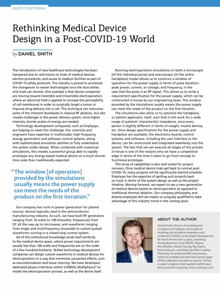
Running electroporation simulations on both a microscopic (of the individual pores) and macroscopic (of the entire handpiece) model allows us to construct a window of operation for the power supply in terms of pulse duration; peak power, current, or voltage; and frequency, in the case that the pulse is an RF signal. This allows us to write a requirement specification for the power supply, which can be constructed in-house by our engineering team. The window provided by the simulations usually means the power supply can meet the needs of the product on the first iteration.
The simulations also allow us to optimize the handpiece, or patient applicator, itself, such that it will work for a wide range of patients’ characteristic impedance, since every person is slightly different in terms of weight, muscle density, etc. Once design specifications for the power supply and handpiece are available, the electronics boards; control systems; and software, including the user interface to the device, can be constructed and integrated seamlessly into the system. The fact that we can execute all stages of this process in-house is one of the reasons why we have a competitive edge in terms of the time it takes to go from concept to functional prototype.
This array of capabilities is also well suited for project recovery. Once medical device trials get back to normal post-COVID-19, many projects will be significantly behind schedule. Emphysys has the expertise of getting such projects back on track in terms of the system design as well as the project timeline. Moving forward, we expect to see a new generation of medical devices based on electroporation as opposed to traditional thermal ablation. Our company philosophy and diverse employee skill set makes us uniquely qualified to take advantage of this industry trend in the coming years.
The introduction of new healthcare technologies has been hampered due to restrictions on trials of medical devices, elective procedures, and access to medical facilities as part of COVID-19 safety protocols. The industry is poised to accelerate the changeover to newer technologies once the dust settles and trials can resume. One example is that device companies are moving toward reversible and irreversible electroporation, where an electrical field is applied to increase the permeability of cell membranes in order to surgically target a tumor or improve drug delivery into a cell. This technique can overcome some of the inherent drawbacks in classical RF ablation, but also creates challenges in the power delivery system, since higher intensity, shorter pulses of energy are needed.
Technology development companies, such as Emphysys, are helping to meet this challenge. Our scientists and engineers have expertise in multimodal, high-frequency energy generation and software control systems, along with sophisticated simulation abilities to fully understand the system under design. When combined with numerical simulations, this creates a powerful group able to rapidly prototype any energy-based medical device on a much shorter time scale than traditionally expected.
Our company has roots in power generation for plasma sources, devices typically used in the semiconductor manufacturing industry. As such, we have built RF generators ranging from 10 watts to 100 kilowatts, frequencies from DC all the way up to microwave, and waveforms ranging from single and multifrequency sinusoidal to custom pulsed waveforms running in a closed-loop control system.
All of this institutional knowledge lends itself perfectly to the medical device space, where power requirements are usually less than 100 watts and frequencies are on the order of a few hundred kilohertz. Skilled technology development companies can design custom waveforms in medical devices for electroporation in a way that minimizes unwanted effects, such as neurostimulation and tissue charring. We have developed dedicated physics interfaces within COMSOL Multiphysics® to model the electroporation process, as well as the device itself.
Daniel Smith, director of modeling and simulation at Emphysys, has 16 years of modeling and simulation experience and worked at COMSOL as the head of development for North America for 12 years, overseeing the development of the MEMS, Plasma, Microfluidics, Particle Tracing, Ray Optics, Semiconductor, and Molecular Flow modules. Previously, he worked at MKS Instruments, where he modeled and optimized various types of fluid calibration and plasma systems. He has a master's degree in both applied mathematics and numerical computing. www.emphysys.com
Rethinking Medical Device Design in a Post-COVID-19 Worldby DANIEL SMITH
ABOUT THE AUTHOR
GUEST EDITORIAL
“The window [of operation] provided by the simulations usually means the power supply can meet the needs of the product on the first iteration."