com the fabulous new · pdf filewith an aggressive viper-like front end and a decidedly...
TRANSCRIPT
A
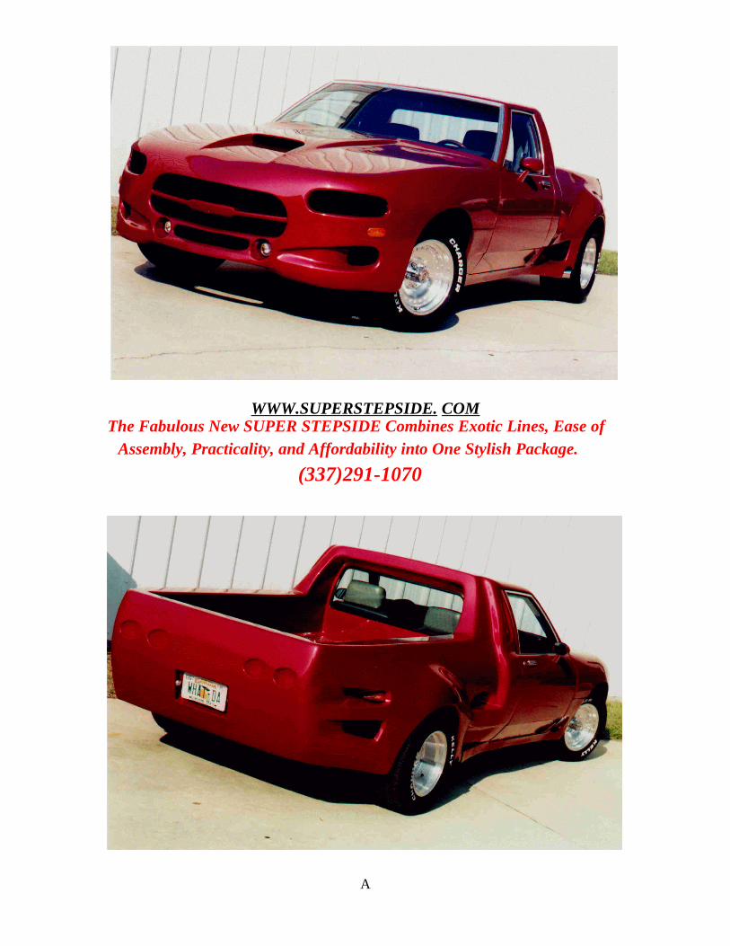
WWW.SUPERSTEPSIDE. COMThe Fabulous New SUPER STEPSIDE Combines Exotic Lines, Ease of
Assembly, Practicality, and Affordability into One Stylish Package.
(337)291-1070
B
BUILDING THE SUPER STEPSIDE
Don Fuselier's Super Stepside prototype pickup first appeared in the May 2001 issue of
Kit Car. As you can see, the lines of the truck are dramatically different, capable of
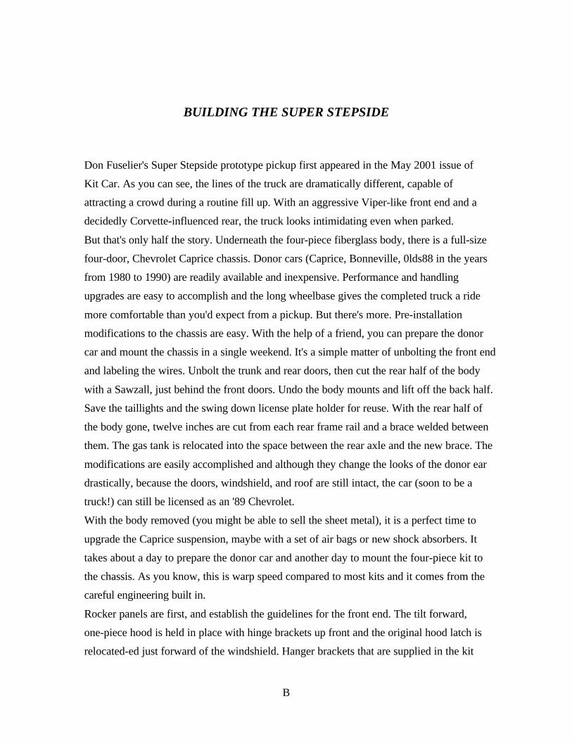
attracting a crowd during a routine fill up. With an aggressive Viper-like front end and a
decidedly Corvette-influenced rear, the truck looks intimidating even when parked.
But that's only half the story. Underneath the four-piece fiberglass body, there is a full-size
four-door, Chevrolet Caprice chassis. Donor cars (Caprice, Bonneville, 0lds88 in the years
from 1980 to 1990) are readily available and inexpensive. Performance and handling
upgrades are easy to accomplish and the long wheelbase gives the completed truck a ride
more comfortable than you'd expect from a pickup. But there's more. Pre-installation
modifications to the chassis are easy. With the help of a friend, you can prepare the donor
car and mount the chassis in a single weekend. It's a simple matter of unbolting the front end
and labeling the wires. Unbolt the trunk and rear doors, then cut the rear half of the body
with a Sawzall, just behind the front doors. Undo the body mounts and lift off the back half.
Save the taillights and the swing down license plate holder for reuse. With the rear half of
the body gone, twelve inches are cut from each rear frame rail and a brace welded between
them. The gas tank is relocated into the space between the rear axle and the new brace. The
modifications are easily accomplished and although they change the looks of the donor ear
drastically, because the doors, windshield, and roof are still intact, the car (soon to be a
truck!) can still be licensed as an '89 Chevrolet.
With the body removed (you might be able to sell the sheet metal), it is a perfect time to
upgrade the Caprice suspension, maybe with a set of air bags or new shock absorbers. It
takes about a day to prepare the donor car and another day to mount the four-piece kit to
the chassis. As you know, this is warp speed compared to most kits and it comes from the
careful engineering built in.
Rocker panels are first, and establish the guidelines for the front end. The tilt forward,
one-piece hood is held in place with hinge brackets up front and the original hood latch is
relocated-ed just forward of the windshield. Hanger brackets that are supplied in the kit
C
are bolted to the original bumper mounts and connect to the hinge supports that are
laminated into the one-piece front end. Match the curves of the front clip to the lines of
the front door by adjusting the hinge brackets. When the cut lines are correct, drill holes in
the bracket and add Grade 8 bolts and nylon lock nuts. Mark the location and reinstall the
original hood latch.
The rear clip is almost as simple. With a little help from your friends, lift the one-piece
fiberglass bed into position with the front portion resting on the sheet metal of the roof.
Use 2X4 shims, 10" long, positioned on the frame rails to temporarily support the rear of
the clip. Proper alignment is achieved when the lines of the clip match the rear door
opening. Special construction hangars supplied with the kit lock the rear of the clip to the
frame rails. Epoxy is used to join the front portion of the fiberglass clip to the sheet metal
of the roof. Once the rear portion is fitted into place, the rocker panels are trimmed for a
precise fit.
Since an elaborate stereo was planned for this kit, the back wall was moved back 5". This
provided additional leg room as well as space for the new stereo. In order to seal the rear
wall from the elements, a basic pattern was created for the piece of 3/4" plywood. The
sheet, mounted just below the back window, is laminated into place and seals the cab. A
local glazier came to the shop and cut glass for the rear window.
Final touches include positioning the headlights under the hood. Rather than connecting
them inside the front clip they are rigidly mounted on a bar that runs behind the radiator.
The lights remain in position when the hood is raised. By using a single Toyota headlamp
and housing on each side, we kept the adjustment mechanism and had minimal problems
connecting the wiring. The same technique is used for the rear lights. The cut-down
Caprice taillight assemblies slip inside the double wall at the rear of truck. 'The light shines
through the four Corvette style cut outs and once again the original wiring is simply
reconnected. The spring loaded license plate was inset into the Stepside's finished opening.
Once it was in place, the gas tank extension tube was trimmed to fit and the cap installed.
We added stainless-steel mesh grilles to the air ducts, chose ultra bright LED lenses for
the parking lights, and used accessory side marker lights in the rear.
All that remained was preparing the body for paint and redoing the interior. Follow along
and see how easily the body is mounted.
Page 1
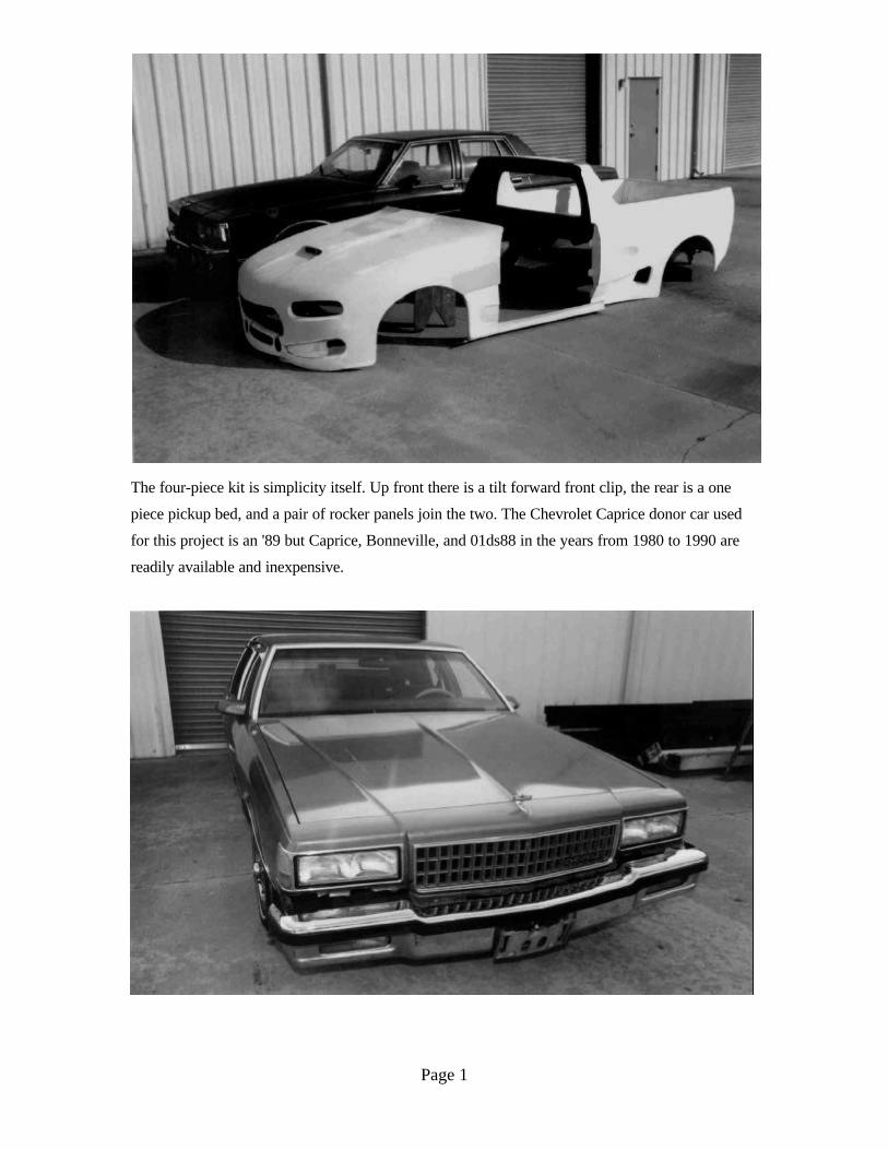
The four-piece kit is simplicity itself. Up front there is a tilt forward front clip, the rear is a one
piece pickup bed, and a pair of rocker panels join the two. The Chevrolet Caprice donor car used
for this project is an '89 but Caprice, Bonneville, and 01ds88 in the years from 1980 to 1990 are
readily available and inexpensive.
Page 2
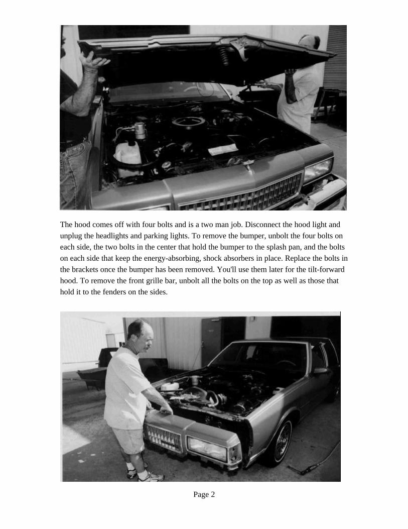
The hood comes off with four bolts and is a two man job. Disconnect the hood light and
unplug the headlights and parking lights. To remove the bumper, unbolt the four bolts on
each side, the two bolts in the center that hold the bumper to the splash pan, and the bolts
on each side that keep the energy-absorbing, shock absorbers in place. Replace the bolts in
the brackets once the bumper has been removed. You'll use them later for the tilt-forward
hood. To remove the front grille bar, unbolt all the bolts on the top as well as those that
hold it to the fenders on the sides.
Page 3
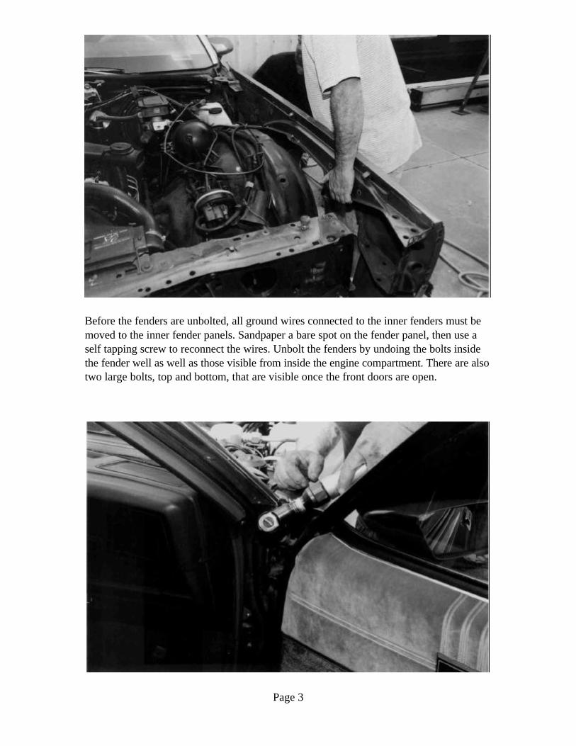
Before the fenders are unbolted, all ground wires connected to the inner fenders must bemoved to the inner fender panels. Sandpaper a bare spot on the fender panel, then use aself tapping screw to reconnect the wires. Unbolt the fenders by undoing the bolts insidethe fender well as well as those visible from inside the engine compartment. There are alsotwo large bolts, top and bottom, that are visible once the front doors are open.
Page 4
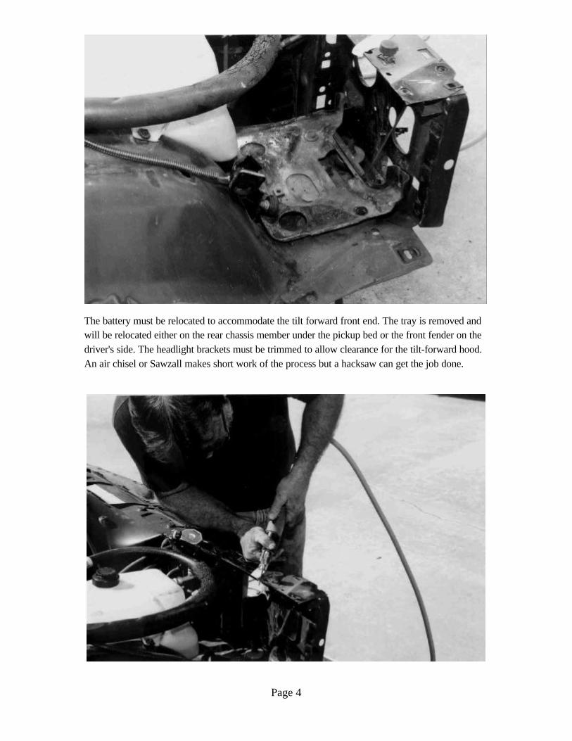
The battery must be relocated to accommodate the tilt forward front end. The tray is removed andwill be relocated either on the rear chassis member under the pickup bed or the front fender on thedriver's side. The headlight brackets must be trimmed to allow clearance for the tilt-forward hood.An air chisel or Sawzall makes short work of the process but a hacksaw can get the job done.
Page 5
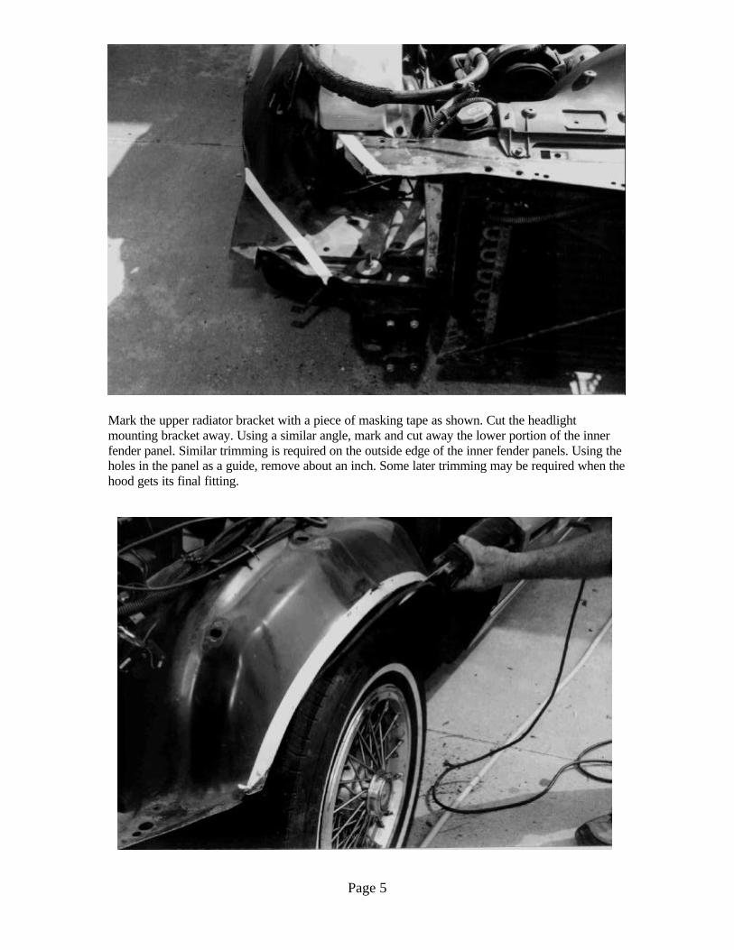
Mark the upper radiator bracket with a piece of masking tape as shown. Cut the headlightmounting bracket away. Using a similar angle, mark and cut away the lower portion of the innerfender panel. Similar trimming is required on the outside edge of the inner fender panels. Using theholes in the panel as a guide, remove about an inch. Some later trimming may be required when thehood gets its final fitting.
Page 6
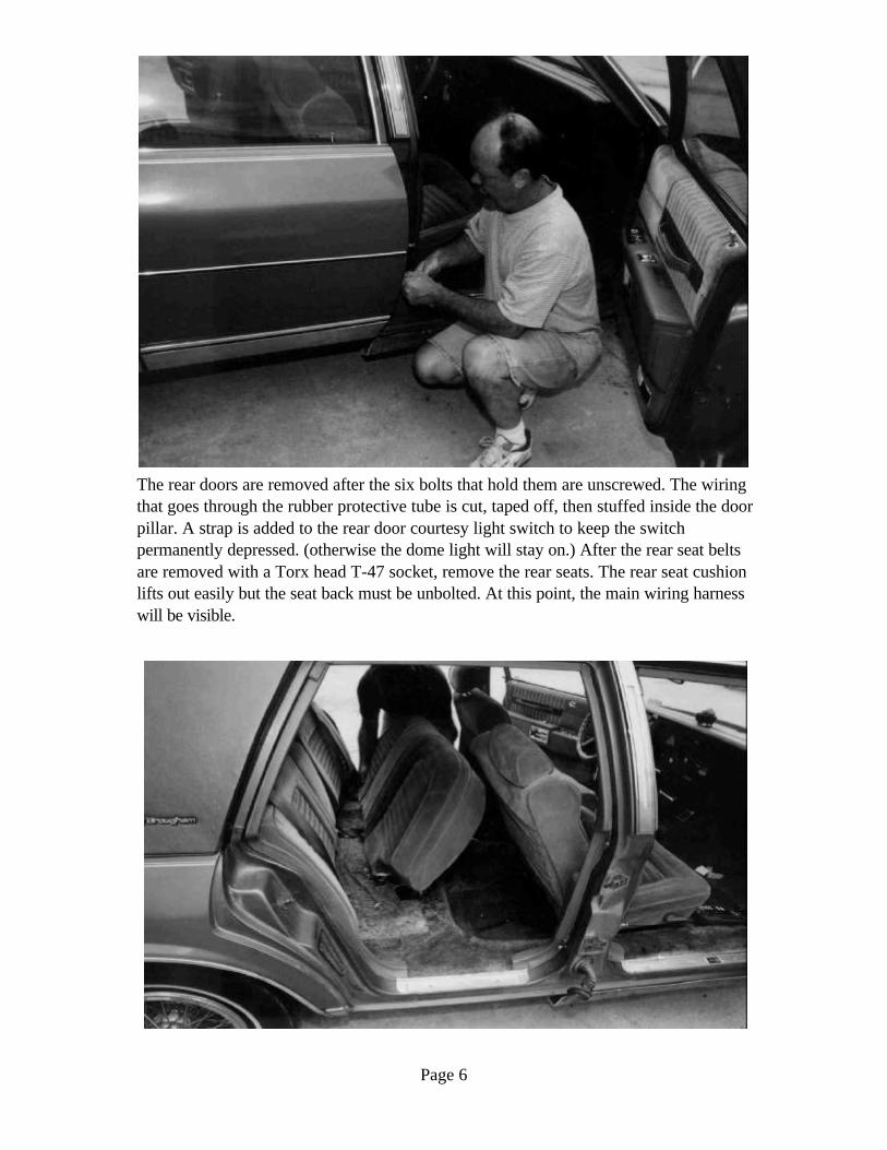
The rear doors are removed after the six bolts that hold them are unscrewed. The wiringthat goes through the rubber protective tube is cut, taped off, then stuffed inside the doorpillar. A strap is added to the rear door courtesy light switch to keep the switchpermanently depressed. (otherwise the dome light will stay on.) After the rear seat beltsare removed with a Torx head T-47 socket, remove the rear seats. The rear seat cushionlifts out easily but the seat back must be unbolted. At this point, the main wiring harnesswill be visible.
Page 7
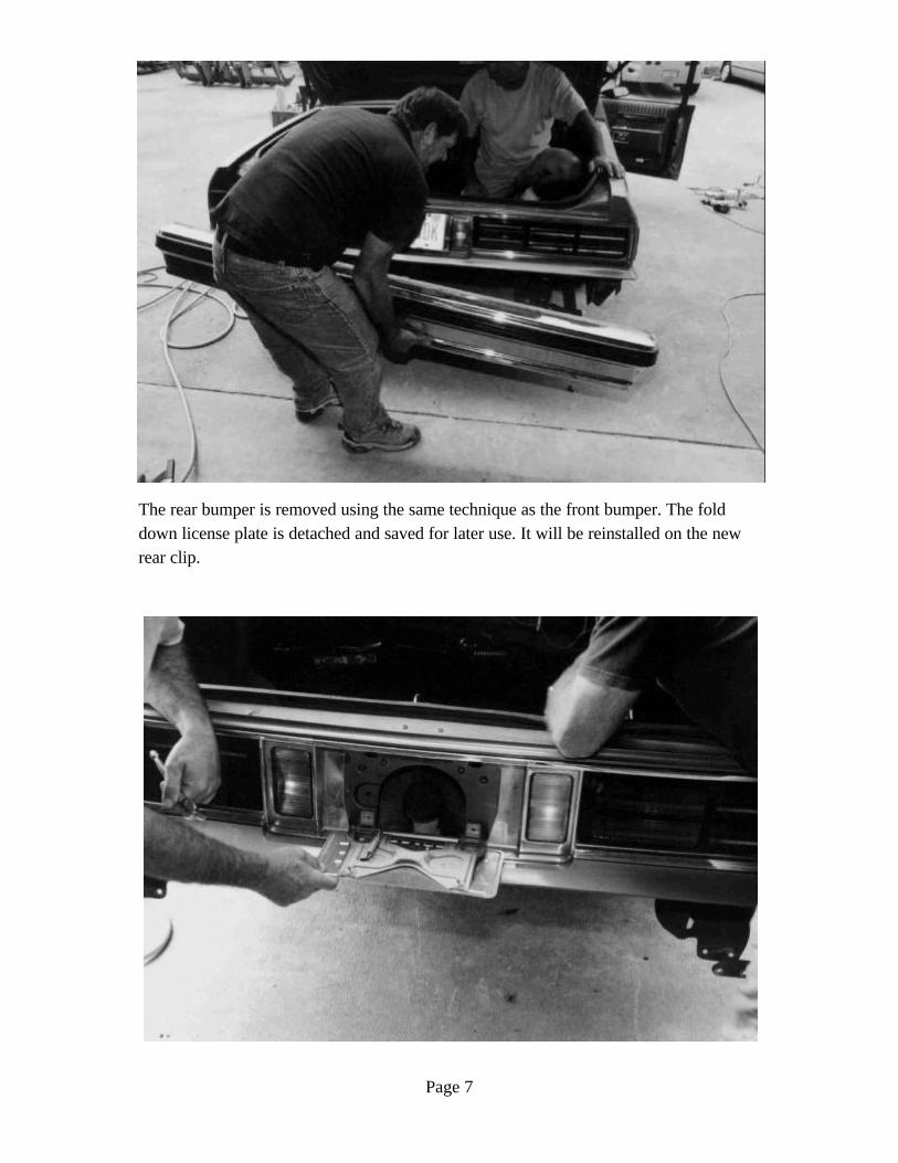
The rear bumper is removed using the same technique as the front bumper. The folddown license plate is detached and saved for later use. It will be reinstalled on the newrear clip.
Page 8
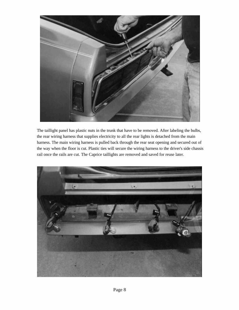
The taillight panel has plastic nuts in the trunk that have to be removed. After labeling the bulbs,the rear wiring harness that supplies electricity to all the rear lights is detached from the mainharness. The main wiring harness is pulled back through the rear seat opening and secured out ofthe way when the floor is cut. Plastic ties will secure the wiring harness to the driver's side chassisrail once the rails are cut. The Caprice taillights are removed and saved for reuse later.
Page 9
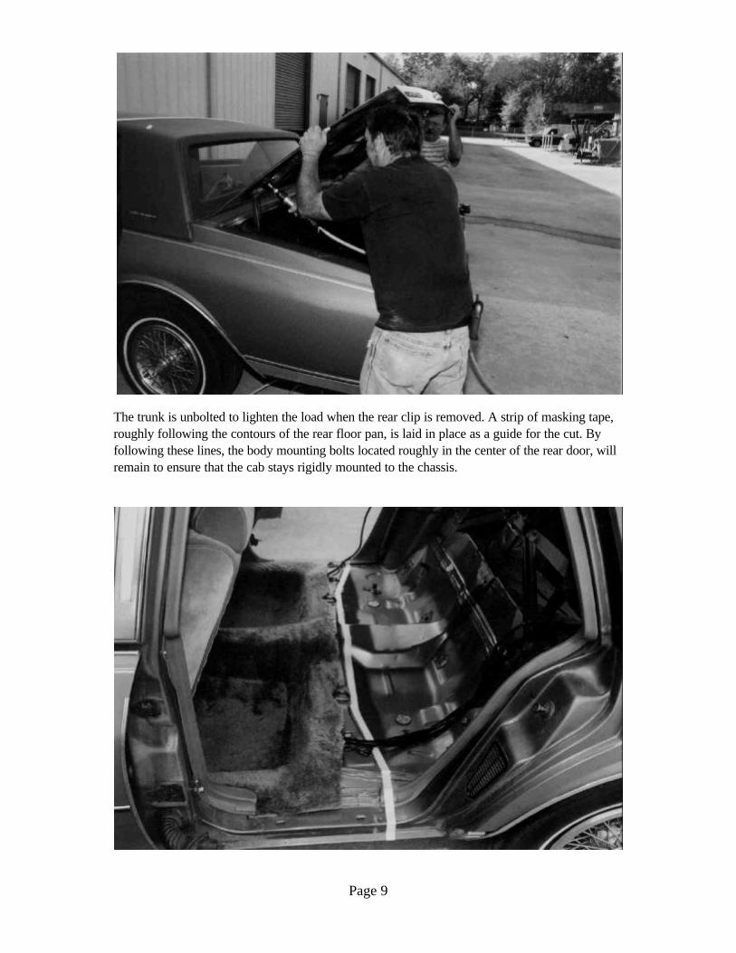
The trunk is unbolted to lighten the load when the rear clip is removed. A strip of masking tape,roughly following the contours of the rear floor pan, is laid in place as a guide for the cut. Byfollowing these lines, the body mounting bolts located roughly in the center of the rear door, willremain to ensure that the cab stays rigidly mounted to the chassis.
Page 10
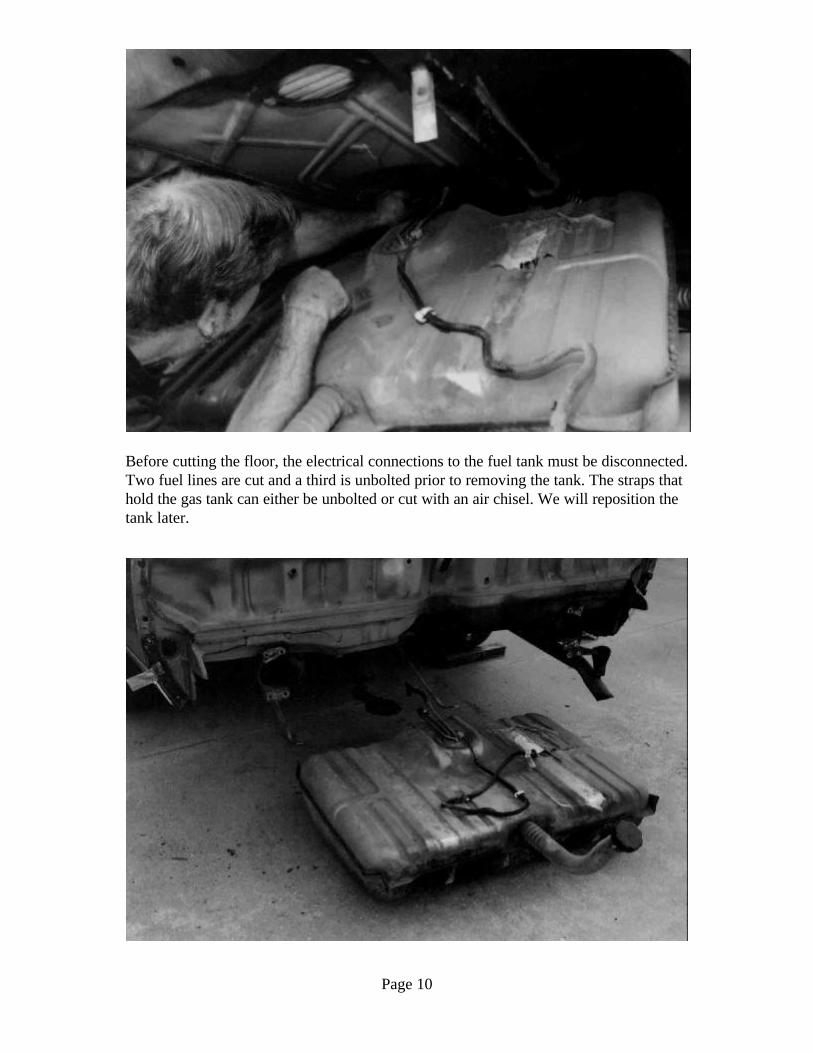
Before cutting the floor, the electrical connections to the fuel tank must be disconnected.Two fuel lines are cut and a third is unbolted prior to removing the tank. The straps thathold the gas tank can either be unbolted or cut with an air chisel. We will reposition thetank later.
Page 11
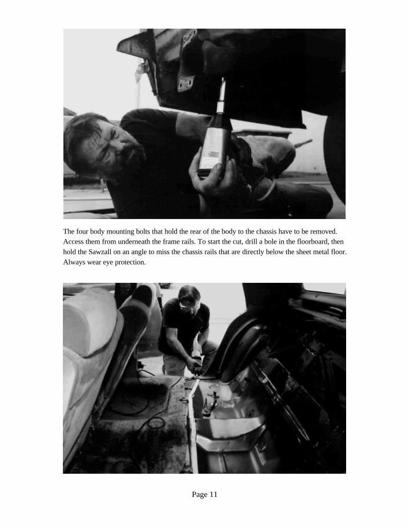
The four body mounting bolts that hold the rear of the body to the chassis have to be removed.Access them from underneath the frame rails. To start the cut, drill a bole in the floorboard, thenhold the Sawzall on an angle to miss the chassis rails that are directly below the sheet metal floor.Always wear eye protection.
Page 12
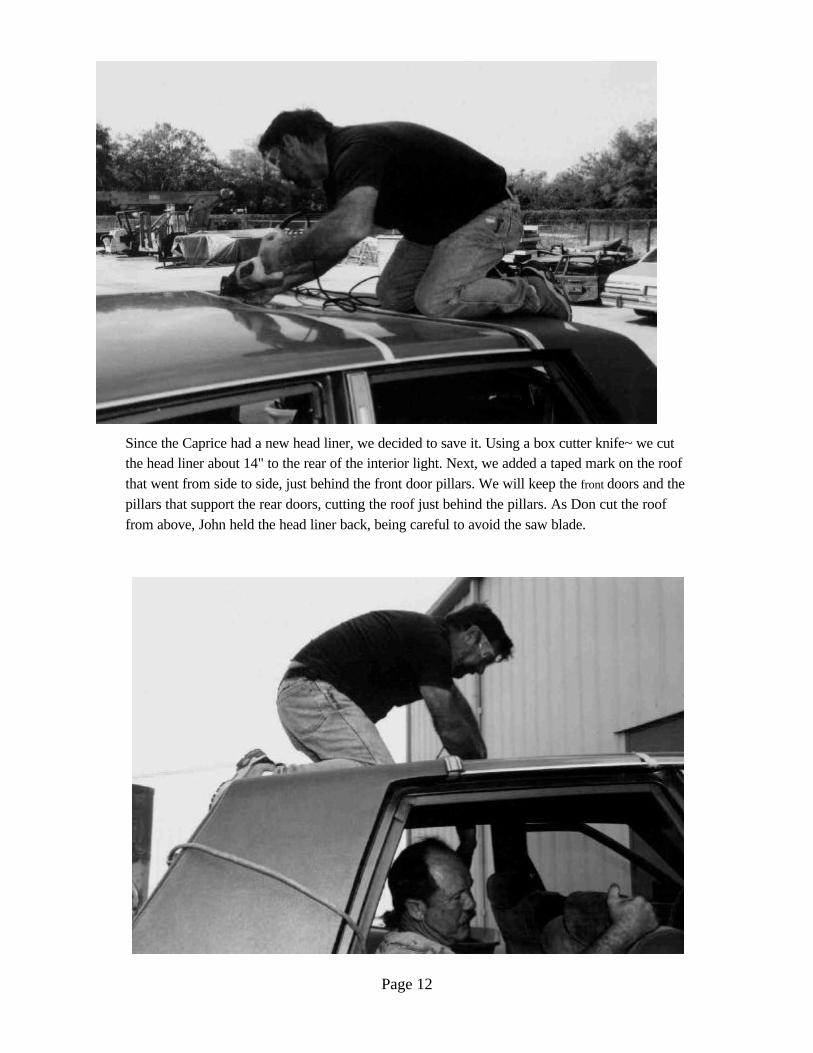
Since the Caprice had a new head liner, we decided to save it. Using a box cutter knife~ we cutthe head liner about 14" to the rear of the interior light. Next, we added a taped mark on the roofthat went from side to side, just behind the front door pillars. We will keep the front doors and thepillars that support the rear doors, cutting the roof just behind the pillars. As Don cut the rooffrom above, John held the head liner back, being careful to avoid the saw blade.
Page 13
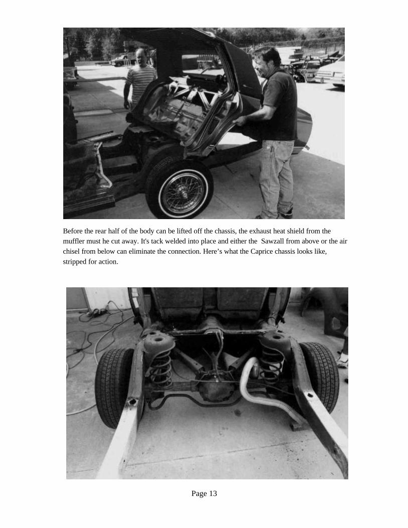
Before the rear half of the body can be lifted off the chassis, the exhaust heat shield from themuffler must he cut away. It's tack welded into place and either the Sawzall from above or the airchisel from below can eliminate the connection. Here’s what the Caprice chassis looks like,stripped for action.
Page 14
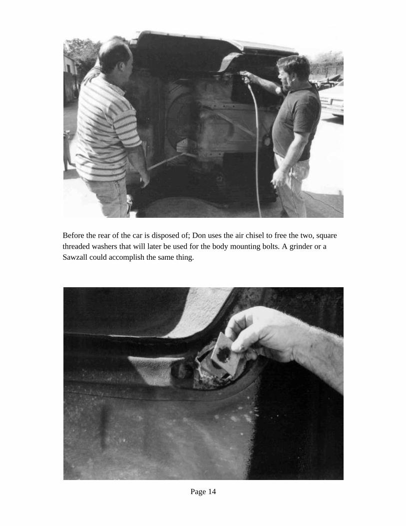
Before the rear of the car is disposed of; Don uses the air chisel to free the two, squarethreaded washers that will later be used for the body mounting bolts. A grinder or aSawzall could accomplish the same thing.
Page 15
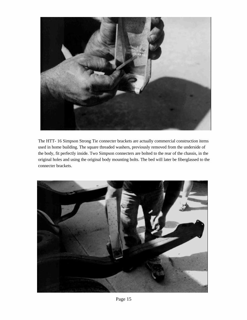
The HTT- 16 Simpson Strong Tie connecter brackets are actually commercial construction itemsused in home building. The square threaded washers, previously removed from the underside ofthe body, fit perfectly inside. Two Simpson connecters are bolted to the rear of the chassis, in theoriginal holes and using the original body mounting bolts. The bed will later be fiberglassed to theconnecter brackets.
Page 16
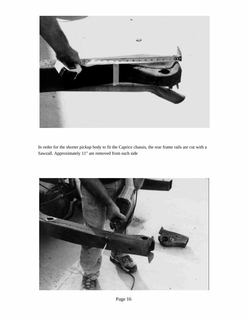
In order for the shorter pickup body to fit the Caprice chassis, the rear frame rails are cut with aSawzall. Approximately 11" are removed from each side
Page 17
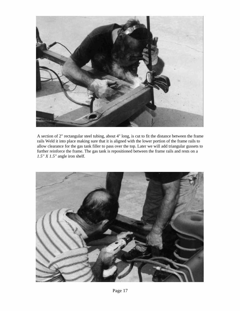
A section of 2" rectangular steel tubing, about 4" long, is cut to fit the distance between the framerails Weld it into place making sure that it is aligned with the lower portion of the frame rails toallow clearance for the gas tank filler to pass over the top. Later we will add triangular gussets tofurther reinforce the frame. The gas tank is repositioned between the frame rails and rests on a1.5" X 1.5" angle iron shelf.
Page 18
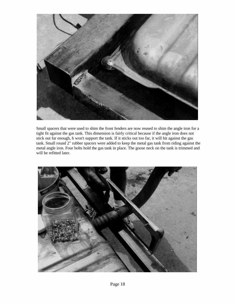
Small spacers that were used to shim the front fenders are now reused to shim the angle iron for atight fit against the gas tank. This dimension is fairly critical because if the angle iron does notstick out far enough, h won't support the tank. If it sticks out too far, it will hit against the gastank. Small round 2" rubber spacers were added to keep the metal gas tank from riding against themetal angle iron. Four bolts hold the gas tank in place. The goose neck on the tank is trimmed andwill be refitted later.
Page 19
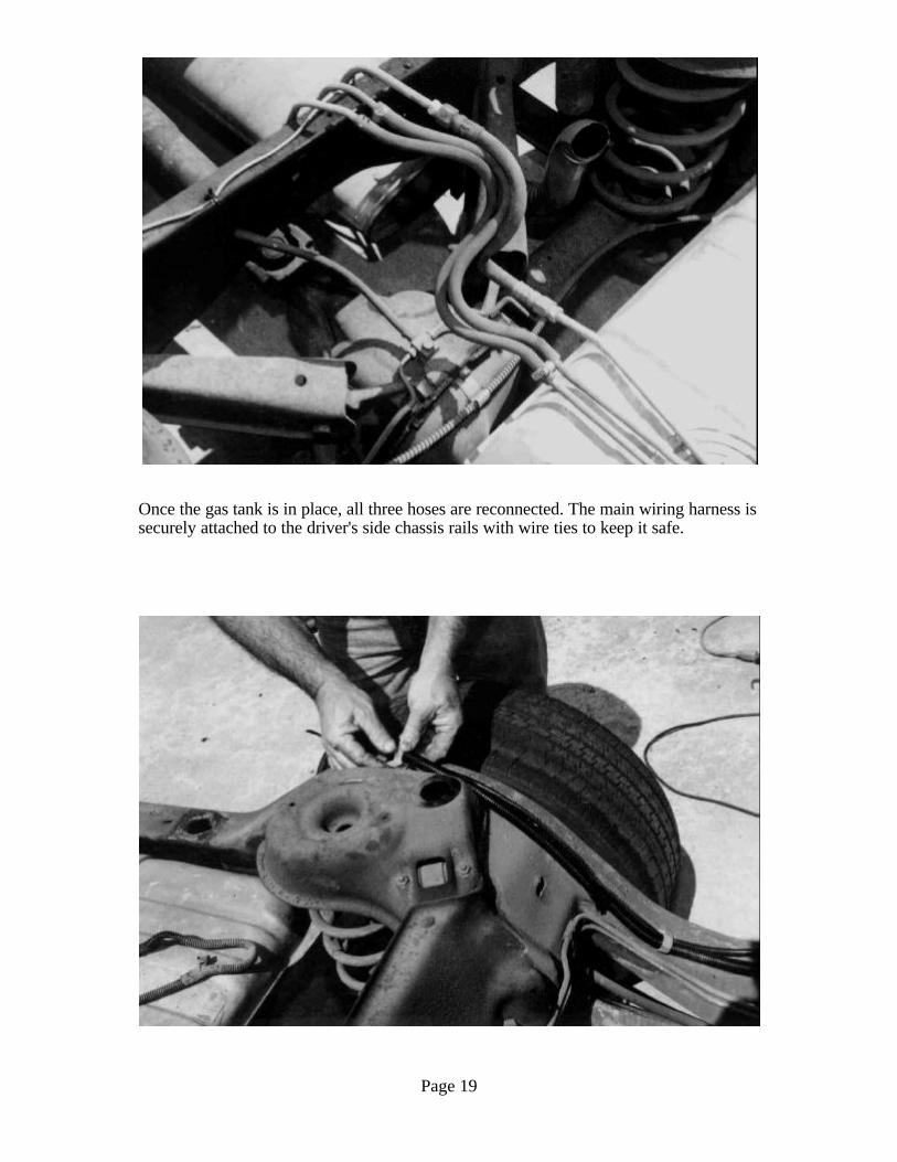
Once the gas tank is in place, all three hoses are reconnected. The main wiring harness issecurely attached to the driver's side chassis rails with wire ties to keep it safe.
Page 20
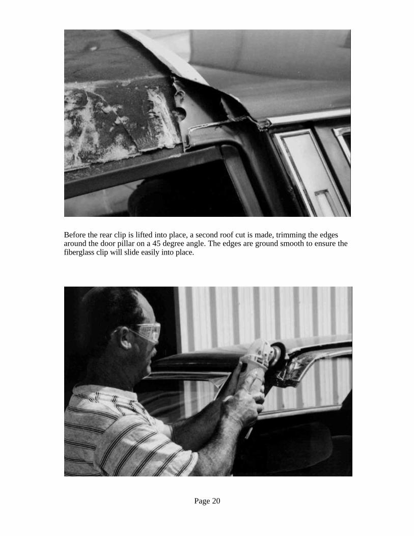
Before the rear clip is lifted into place, a second roof cut is made, trimming the edgesaround the door pillar on a 45 degree angle. The edges are ground smooth to ensure thefiberglass clip will slide easily into place.
Page 21
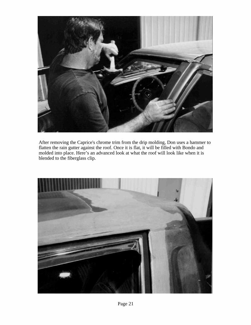
After removing the Caprice's chrome trim from the drip molding, Don uses a hammer toflatten the rain gutter against the roof. Once it is flat, it will be filled with Bondo andmolded into place. Here’s an advanced look at what the roof will look like when it isblended to the fiberglass clip.
Page 22
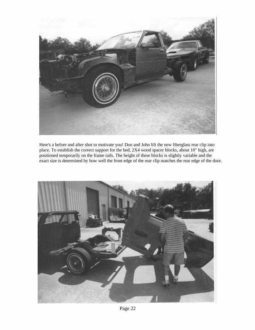
Here's a before and after shot to motivate you! Don and John lift the new fiberglass rear clip intoplace. To establish the correct support for the bed, 2X4 wood spacer blocks, about 10" high, arepositioned temporarily on the frame rails. The height of these blocks is slightly variable and theexact size is determined by how well the front edge of the rear clip matches the rear edge of the door.
Page 23
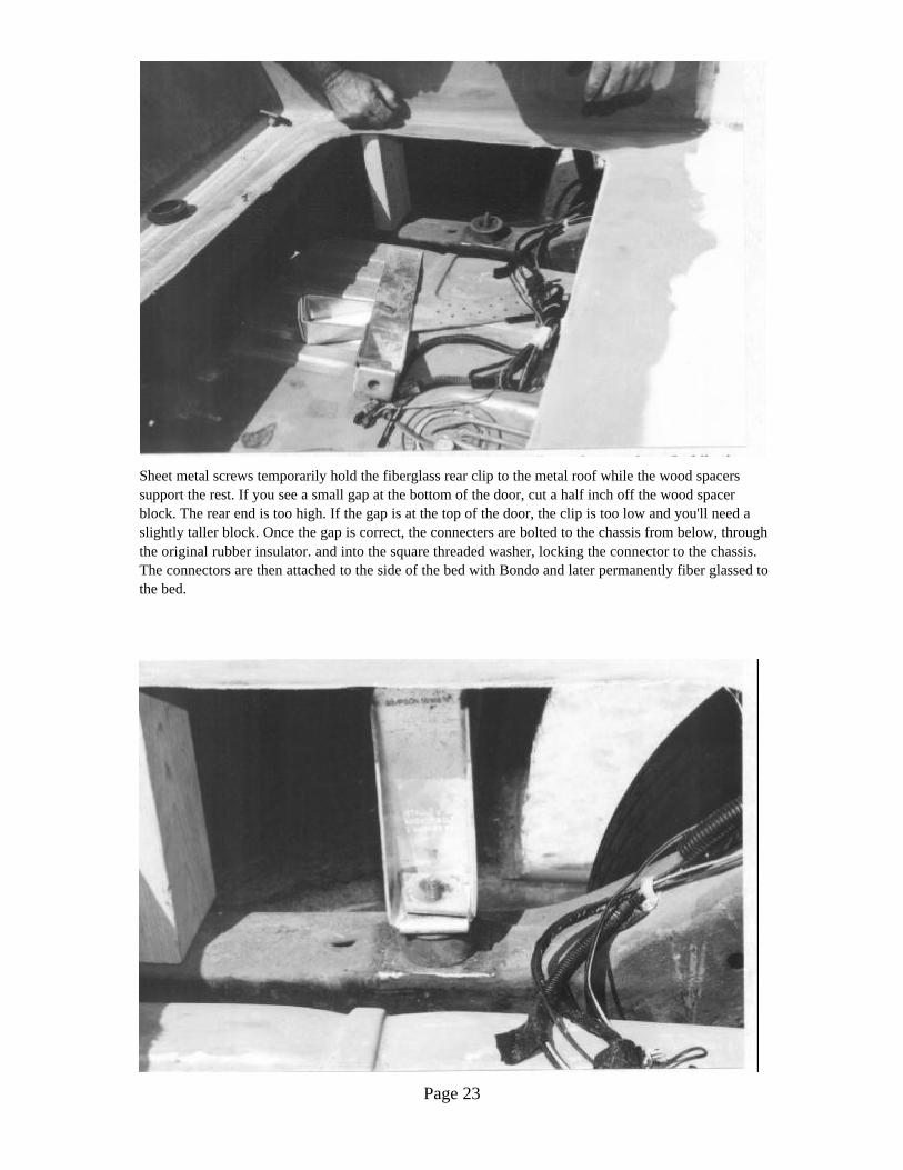
Sheet metal screws temporarily hold the fiberglass rear clip to the metal roof while the wood spacerssupport the rest. If you see a small gap at the bottom of the door, cut a half inch off the wood spacerblock. The rear end is too high. If the gap is at the top of the door, the clip is too low and you'll need aslightly taller block. Once the gap is correct, the connecters are bolted to the chassis from below, throughthe original rubber insulator. and into the square threaded washer, locking the connector to the chassis.The connectors are then attached to the side of the bed with Bondo and later permanently fiber glassed tothe bed.
Page 24
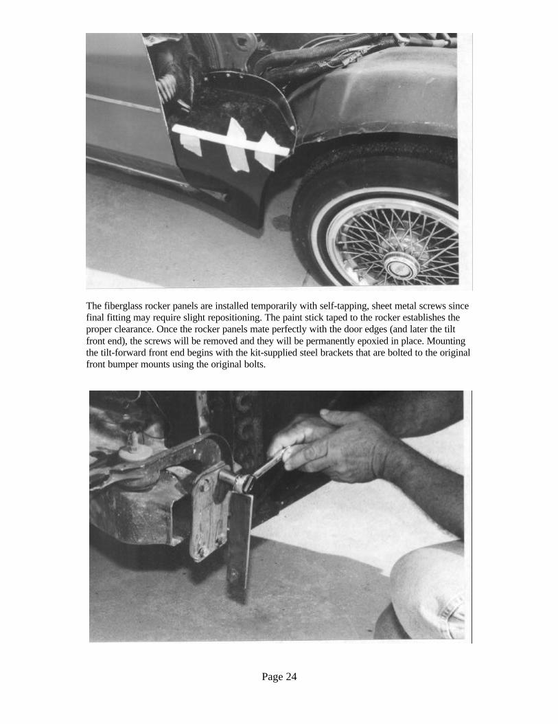
The fiberglass rocker panels are installed temporarily with self-tapping, sheet metal screws since final fitting may require slight repositioning. The paint stick taped to the rocker establishes theproper clearance. Once the rocker panels mate perfectly with the door edges (and later the tiltfront end), the screws will be removed and they will be permanently epoxied in place. Mountingthe tilt-forward front end begins with the kit-supplied steel brackets that are bolted to the originalfront bumper mounts using the original bolts.
Page 25
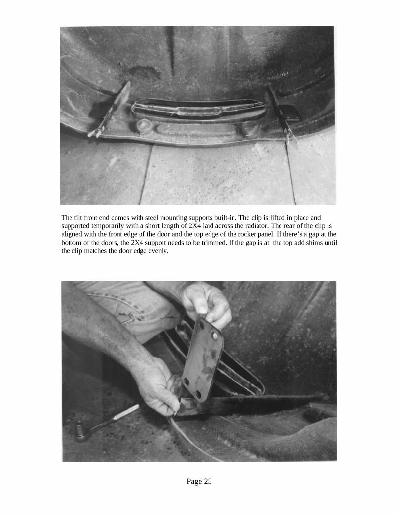
The tilt front end comes with steel mounting supports built-in. The clip is lifted in place andsupported temporarily with a short length of 2X4 laid across the radiator. The rear of the clip isaligned with the front edge of the door and the top edge of the rocker panel. If there’s a gap at thebottom of the doors, the 2X4 support needs to be trimmed. lf the gap is at the top add shims untilthe clip matches the door edge evenly.
Page 26
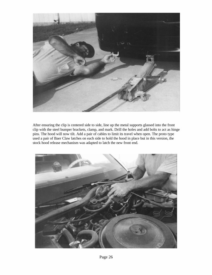
After ensuring the clip is centered side to side, line up the metal supports glassed into the frontclip with the steel bumper brackets, clamp, and mark. Drill the holes and add bolts to act as hingepins. The hood will now tilt. Add a pair of cables to limit its travel when open. The proto typeused a pair of Baer Claw latches on each side to hold the hood in place but in this version, thestock hood release mechanism was adapted to latch the new front end.
Page 27
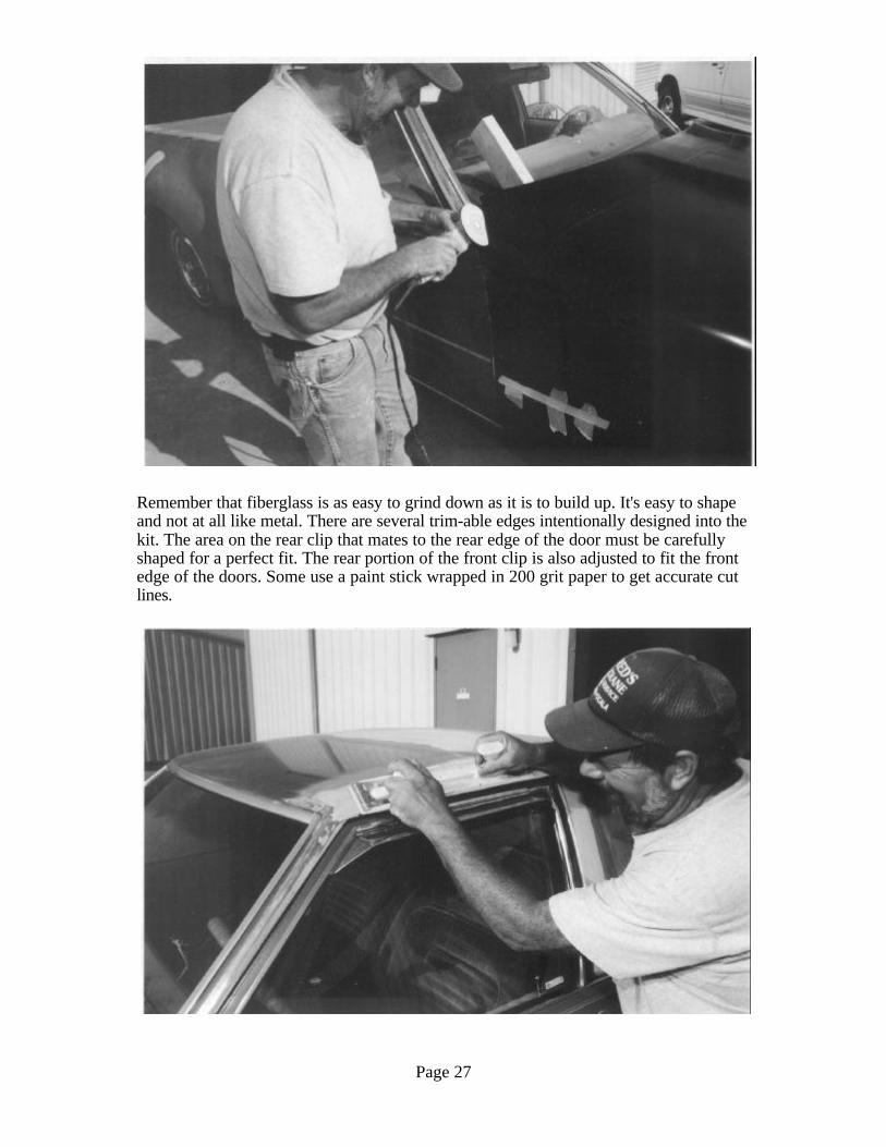
Remember that fiberglass is as easy to grind down as it is to build up. It's easy to shapeand not at all like metal. There are several trim-able edges intentionally designed into thekit. The area on the rear clip that mates to the rear edge of the door must be carefullyshaped for a perfect fit. The rear portion of the front clip is also adjusted to fit the frontedge of the doors. Some use a paint stick wrapped in 200 grit paper to get accurate cutlines.
Page 28
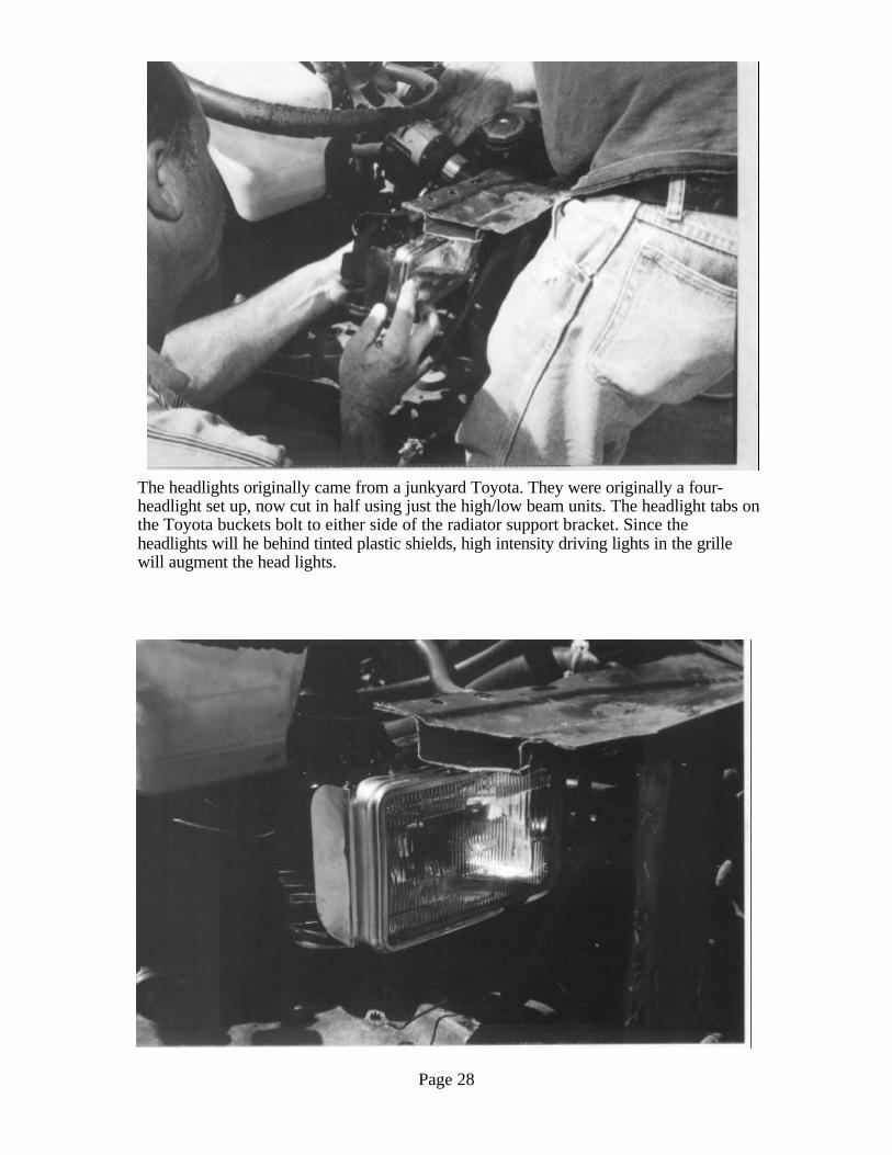
The headlights originally came from a junkyard Toyota. They were originally a four-headlight set up, now cut in half using just the high/low beam units. The headlight tabs onthe Toyota buckets bolt to either side of the radiator support bracket. Since theheadlights will he behind tinted plastic shields, high intensity driving lights in the grillewill augment the head lights.
Page 29
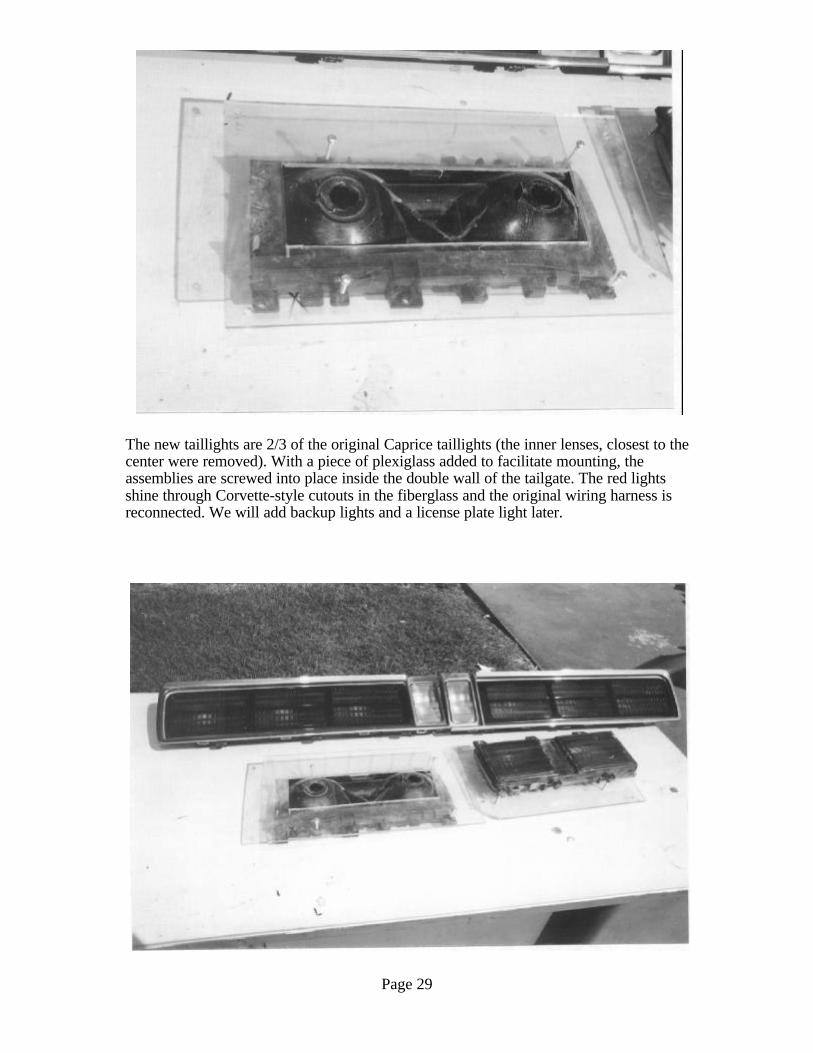
The new taillights are 2/3 of the original Caprice taillights (the inner lenses, closest to thecenter were removed). With a piece of plexiglass added to facilitate mounting, theassemblies are screwed into place inside the double wall of the tailgate. The red lightsshine through Corvette-style cutouts in the fiberglass and the original wiring harness isreconnected. We will add backup lights and a license plate light later.
Page 30
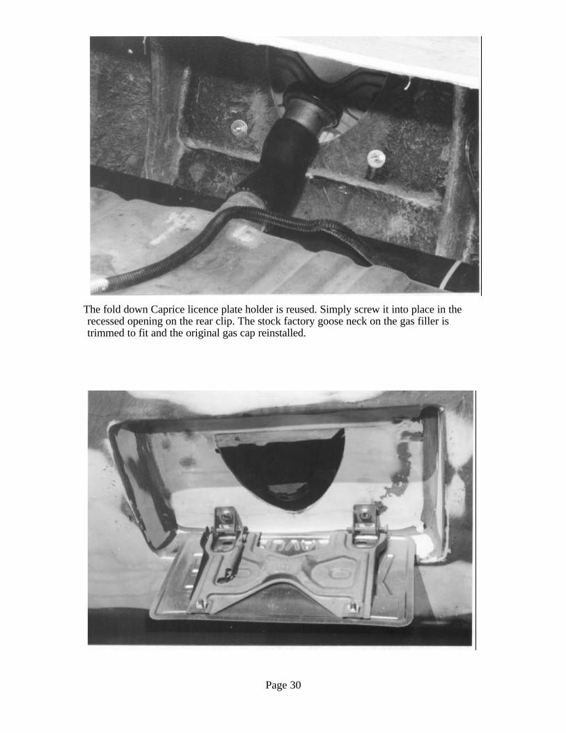
The fold down Caprice licence plate holder is reused. Simply screw it into place in the recessed opening on the rear clip. The stock factory goose neck on the gas filler istrimmed to fit and the original gas cap reinstalled.
Page 31
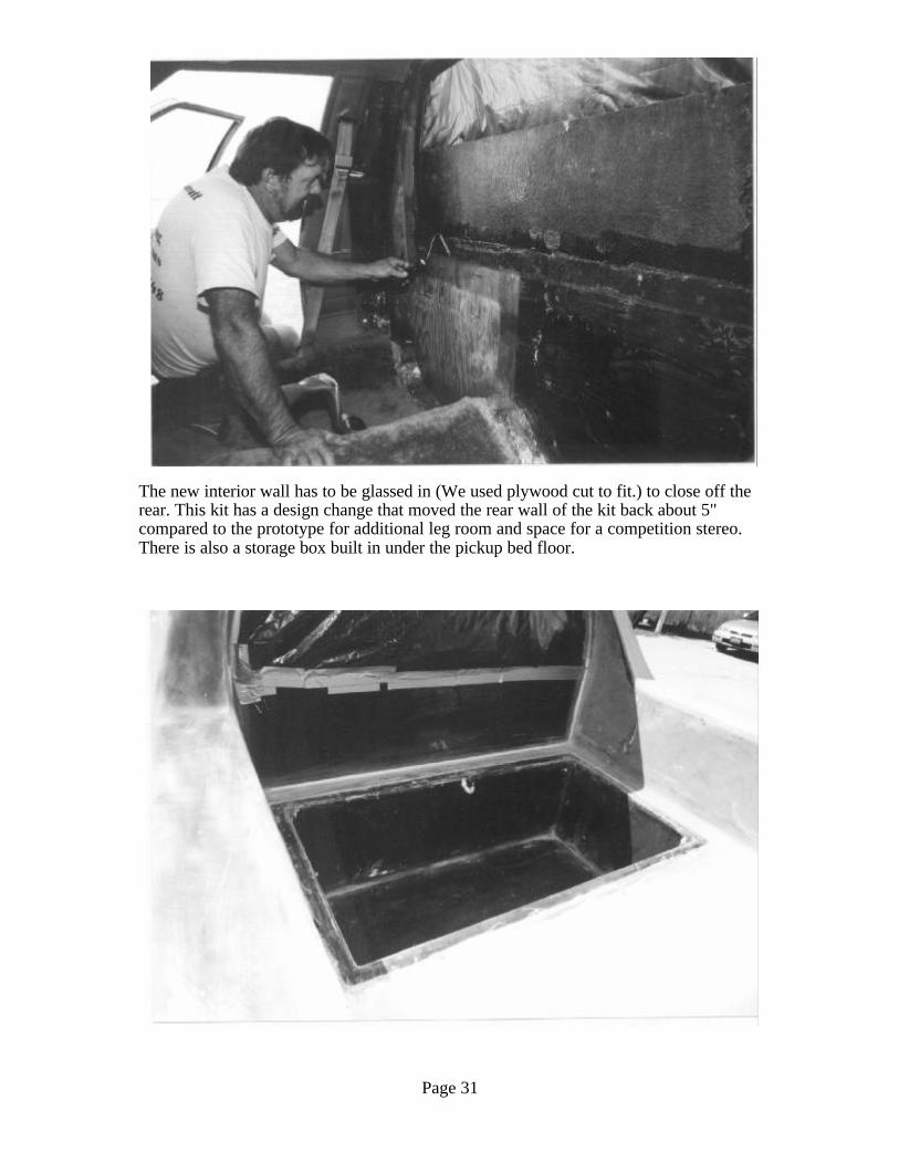
The new interior wall has to be glassed in (We used plywood cut to fit.) to close off therear. This kit has a design change that moved the rear wall of the kit back about 5"compared to the prototype for additional leg room and space for a competition stereo.There is also a storage box built in under the pickup bed floor.
Page 32
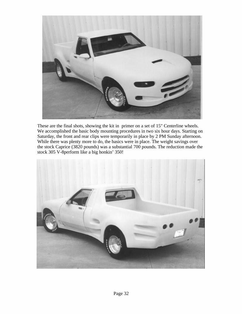
These are the final shots, showing the kit in primer on a set of 15" Centerline wheels.We accomplished the basic body mounting procedures in two six hour days. Starting onSaturday, the front and rear clips were temporarily in place by 2 PM Sunday afternoon.While there was plenty more to do, the basics were in place. The weight savings overthe stock Caprice (3820 pounds) was a substantial 700 pounds. The reduction made thestock 305 V-8perform like a big honkin’ 350!

Page 33
NOTES