$#-&4 8*3&4 range of world-class hv, mv and lv cables includes single & multi core...
TRANSCRIPT


1
NUHAS OMAN – QUALITY & RELIABILITY.
INTRODUCTION Nuhas Oman LLC, an integral part of The Al Bahja Group of Companies, is a Quality producer of:
• HV, MV and LV Cables
• Enamelled Copper Wires
• Oxygen Free Continuous Cast Copper Wire Rods
• Drawn Copper Conductors
Our state-of-the-art manufacturing facilities with cutting edge technology ensure that our products meet with
highest quality standards. All our products utilize only OXYGEN FREE HIGH CONDUCTIVITY
ELECTRONIC GRADE Copper produced through the Outokompu UPCAST technology, producing minimum
99.99% pure copper with oxygen content less than 5 ppm. The usage of
Our range of World-class HV, MV and LV Cables includes Single & Multi Core Armoured and Un-armoured
Cables, Specialty, Control, Instrumentation and also LSF, FRLS, LSOH & Custom Cables to meet the
requirements of a broad spectrum of applications ranging from
The Cables are produced in compliance to the requirements of BS, IEC, VDE, ASTM, ICEA & UL
specifications. The by acclaimed independent international certifying agencies
confirming compliance to respective standards.
Nuhas that conform to relevant International standards and
Our quality cycle encompasses raw material and consumable sourcing, in-process production controls and
certification of finished goods prior to delivery. A well-equipped in-house quality assurance facility, manned by
qualified professionals from the industry, ensures that all products delivered meet stringent quality controls
and parameters. Our state-of-the-art laboratory is equipped to test as per relevant international standards as
also to individual customer specifications.
The company endeavours to cater to the domestic, regional and global markets while maintaining the sanctity
of our pristine environment.
is a continuing process at Nuhas Oman LLC and we at Nuhas Oman ceaselessly
strive to achieve product excellence through TOTAL QUALITY MANAGEMENT to provide the best value to
our customers.

2 3
SINGLE CORE PVC INSULATED FLEXIBLE CABLES
Type H05V-K, H07V-K Applications Flexible wire, for protected installation in
equipment and lighting fitting conduit or under plaster
Standards BS 6004:2000
Construction 1) Fine stranded Oxygen Free Electronic copper wire 2) PVC Insulation
Packing In rolls of 100 yards, spools, drums or as per customer requirements
Technical Data
Max. Operating Temperature: 70 0 C Rated Voltage: 300/500 V H05V-K 450/750 V H07V-K
NOMINAL CROSS SECTION
CLASS OF COPPER
CON- DUCTOR
INSULATION THICKNESS
MAX. OVERALL DIAMETER
APPROX. NET WEIGHT
STANDARD LENGTH
(mm 2 ) (mm Nominal) (mm) (kg/km) H05V-K 300/500 V Yards
0.5 5 0.6 2.5 9 100
0.75 5 0.6 2.7 11 100
1.0 5 0.6 2.8 14 100
H07V-K 450/750 V
1.5 5 0.7 3.4 21 100
2.5 5 0.8 4.1 32 100
4 5 0.8 4.8 47 100
6 5 0.8 5.3 66 100
Meters 10 5 1.0 6.8 110 300
16 5 1.0 8.1 170 300
25 5 1.2 10.2 266 1000
35 5 1.2 11.7 360 1000
50 5 1.4 13.9 494 1000
70 5 1.4 16.0 696 1000
95 5 1.6 18.2 965 1000
120 5 1.6 20.2 1203 1000
150 5 1.8 22.5 1483 1000
185 5 2.0 24.9 1852 1000
240 5 2.2 28.4 2424 1000
SINGLE CORE PVC INSULATED CABLES
Type H05V-U, H07V-U, H07V R Applications Standards BS 6004:2000
Construction 1) Oxygen Free Electronic Copper Conductor 2) PVC Insulation
Packing In rolls of 100 yards, spools, drums or as per customer requirements
Technical Data
Max. Operating Temperature: 70 º C Rated Voltage: 300/500 V (H05V-U) 450/750 V(H07V-U, H07V-R)
NOMINAL CROSS SECTION
CLASS OF COPPER
CON- DUCTOR
INSULATION THICKNESS
MAX. OVERALL DIAMETER
APPROX. NET WEIGHT
STANDARD LENGTH
(mm 2 ) (mm Nominal) (mm) (kg/km)
H05V-U 300/500 V Yards 0.50 1 0.6 2.3 9 100 0.75 1 0.6 2.5 11 100 1.0 1 0.6 2.7 14 100
H07V-U 450/750 V 1.5 1 0.7 3.2 21 100 2.5 1 0.8 3.9 32 100 4 1 0.8 4.4 47 100 6 1 0.8 5.0 66 100
H07V-R 450/750 V 1.5 2 0.7 3.3 21 100 2.5 2 0.8 4.0 32 100 4 2 0.8 4.6 47 100 6 2 0.8 5.2 66 100
Meters 10 2 1.0 6.7 115 300 16 2 1.0 7.8 175 300 25 2 1.2 9.3 260 1000 35 2 1.2 10.5 350 1000 50 2 1.4 11.9 480 1000 70 2 1.4 13.6 670 1000 95 2 1.6 15.7 925 1000 120 2 1.6 17.2 1150 1000 150 2 1.8 19.0 1415 1000 185 2 2.0 21.1 1775 1000 240 2 2.2 23.8 2320 1000 300 2 2.4 26.5 2895 1000 400 2 2.6 29.6 3695 1000 500 2 2.8 33.0 4720 1000 630 2 2.8 36.7 6030 500
In dry rooms, in apparatus, switch and distribution boards, for laying in conduit on and under plaster and on insulating supports above plaster

4 5
HEAT RESISTANT SINGLE CORE PVC INSULATED CABLES
Type H07V2-R H07V2-U Applications In dry rooms, in apparatus, switch and
distribution boards, for laying in conduit on and under plaster and on insulating supports above plaster
Standards BS 6004:2000
Construction 1) Oxygen Free Electronic Copper Conductor 2) HR PVC Insulation
Packing In rolls of 100 yards, spools, drums or as per customer requirements
Technical Data
Max. Operating Temperature: 90 º C Rated Voltage: 450/750 V
NOMINAL CROSS SECTION
CLASS OF COPPER
CON- DUCTOR
INSULATION THICKNESS
MAX. OVERALL DIAMETER
APPROX. NET WEIGHT
STANDARD LENGTH
(mm 2 ) (mm Nominal) (mm) (kg/km)
H07V2-U 450/750 V Yards 1.5 1 0.7 3.2 21 100
2.5 1 0.8 3.9 32 100
4 1 0.8 4.4 47 100
6 1 0.8 5.0 66 100
H07V2-R 450/750 V 1.5 2 0.7 3.3 21 100
2.5 2 0.8 4.0 32 100
4 2 0.8 4.6 47 100
6 2 0.8 5.2 66 100
Meters 10 2 1.0 6.7 110 300
16 2 1.0 7.8 170 300
25 2 1.2 9.3 255 1000
35 2 1.2 10.5 345 1000
50 2 1.4 11.9 470 1000
70 2 1.4 13.6 665 1000
95 2 1.6 15.7 920 1000
120 2 1.6 17.2 1145 1000
150 2 1.8 19.0 1410 1000
185 2 2.0 21.1 1765 1000
240 2 2.2 23.8 2310 1000
300 2 2.4 26.5 2885 1000
400 2 2.6 29.6 3685 1000
500 2 2.8 33.0 4710 1000
630 2 2.8 36.7 6030 500
HEAT RESISTANT SINGLE CORE PVC INSULATED FLEXIBLE CABLES
Type H07V2K Applications Flexible wire, for protected installation in equipment and lighting fitting conduit or under plaster
Standards BS 6004:2000
Construction 1) Fine stranded Oxygen Free Electronic copper wire 2) HR PVC Insulation
Packing In rolls of 100 yards, spools, drums or as per customer requirements
Technical Data
Max. Operating Temperature: 90 0 C Rated Voltage: 450/750 V
NOMINAL CROSS SECTION
CLASS OF COPPER
CON- DUCTOR
INSULATION THICKNESS
MAX. OVERALL DIAMETER
APPROX. NET WEIGHT
STANDARD LENGTH
(mm 2 ) (mm Nominal) (mm) (kg/km)
H07V2-K 450/750 V Yards
1.5 5 0.7 3.4 21 100
2.5 5 0.8 4.1 32 100
4 5 0.8 4.8 47 100
6 5 0.8 5.3 66 100
Meters 10 5 1.0 6.8 110 300
16 5 1.0 8.1 170 300
25 5 1.2 10.2 266 1000
35 5 1.2 11.7 360 1000
50 5 1.4 13.9 494 1000
70 5 1.4 16.0 696 1000
95 5 1.6 18.2 965 1000
120 5 1.6 20.2 1203 1000
150 5 1.8 22.5 1483 1000
185 5 2.0 24.9 1852 1000
240 5 2.2 28.4 2424 1000

6 7
FLEXIBLE CIRCULAR TWIN 2, 3, 4 & 5 CORE CABLES
Reference Standards
BS 6500:2000 Applications For household appliances under
medium mechanical stresses, also in damp and wet conditions Construction 1) Oxygen Free Electronic
Copper Conductor – Class 5 2) PVC Insulation Type TI 2 3) PVC Sheath – Type TM 2
Packing In coils/drums or as per customer requirements
Technical Data
Rated Voltage: 300/500 V Temperature: 70°C
No. of cores Nominal Cross
Section Nominal
Insulation thickness
Nominal Sheath
Thickness
Approx. cable dia.
Approx. weight per km.
mm 2 (mm) (mm) (mm) (kg.)
2 0.75 0.6 0.8 6.5 70
2 1.0 0.6 0.8 6.7 75
2 1.5 0.7 0.8 7.8 100
2 2.5 0.8 1.0 9.5 150
3 0.75 0.6 0.8 6.7 75
3 1.0 0.6 0.8 7.0 90
3 1.5 0.7 0.9 8.4 120
3 2.5 0.8 1.0 10.6 185
4 0.75 0.6 0.80 7.5 90
4 1.0 0.6 0.90 8.0 110
4 1.5 0.7 1.00 9.5 160
4 2.5 0.8 1.10 11.6 230
5 0.75 0.6 0.9 8.2 105
5 1.0 0.6 0.9 8.7 120
5 1.5 0.7 1.10 10.6 175
5 2.5 0.8 1.20 13.0 265
No. of cores Nominal Cross
Section Nominal
Insulation thickness
Approx. cable dia. Approx. weight per
km.
(No.) (mm 2 ) (mm) (mm) (kg.)
2 1.0 0.6 7.3 70
2 1.5 0.7 8.7 97
2 2.5 0.8 9.9 130
3 1.0 0.6 7.7 90
3 1.5 0.7 9.2 125
3 2.5 0.8 10.5 170
Temperature: 70°C requirements
FIRE ALARM / SIGNAL CABLES
Reference Standards
BS 7629-1, BS 6387 Category CWZ
Applications In populated places where there is risk of fire. Can be used in wide variety of applications including voice alarm, fire and security circuits and networking
requirements due to excellent data/ signal transmission characteristics
Voltage: 300/500 V
Construction 1) Oxygen Free Electronic Copper Conductor
2) Mica tape 3) FRLSOH Insulation 4) Overall Screen with Aluminium
Mylar tape and Tinned copper drain wire
5) FRLSOH Sheath
Packing In coils/drums or as per customer Technical Data

8 9
FLAT CABLES WITHOUT EARTH CONDUCTOR
Reference Standards
BS 6004:2000 Applications Fixed installation in dry or damp
premises, electric power & lighting devices, telecommunication appliances
Voltage: 300/500 V. Temperature : 70 0 C
Construction 1) Oxygen Free Electronic Copper Conductor
2) PVC Insulation 3) PVC Sheath
Packing In drums or as per customers requirements
Technical Data
No. of cores Nominal cross-sectional
area of conductors mm 2
Radial thickness of Insulation (mm)
Mean overall dimension (mm)
2 1.0 0.6 4.7 x 7.4 2 1.5 0.7 5.4 x 8.4 2 2.5 0.8 6.2 x 9.8 2 4.0 0.8 7.2 x 11.5 2 6.0 0.8 8.0 x 13.0 2 10.0 1.0 9.6 x 16.0 2 16.0 1.0 11.0 x 18.5 3 1.0 0.6 4.7 x 9.8 3 1.5 0.7 5.4 x 11.5 3 2.5 0.8 6.2 x 13.5 3 4.0 0.8 7.4 x 16.5 3 6.0 0.8 8.0 x 18.0 3 10.0 1.0 9.6 x 22.5 3 16.0 1.0 11.0 x 26.5
FLAT CABLES WITH EARTH CONDUCTOR
Standards BS 6004:2000 Applications Fixed installation in dry or damp
premises Construction 1) Oxygen Free Electronic Copper Conductor
2) PVC Insulation 3) PVC Sheath 4) Earth Conductor
Packing In drums or as per customer requirements
Technical Data
Voltage: 300/500 V. Temperature : 70 0 C
No. of cores Copper
conductor mm 2
Thickness of Insulation (mm)
Approx. overall dimension (mm)
Earth Conductor, minimum nominal cross-
sectional area mm 2
2 1.0 0.6 4.7 x 8.6 1 2 1.5 0.7 5.4 x 9.6 1 2 2.5 0.8 6.2 x 11.5 1.5 2 4.0 0.8 7.2 x 13.0 1.5 2 6.0 0.8 8.0 x 15.0 2.5 2 10.0 1.0 9.6 x 19.0 4 2 16.0 1.0 11.0 x 22.5 6 3 1.0 0.6 4.7 x 11.0 1 3 1.5 0.7 5.4 x 12.5 1 3 2.5 0.8 6.2 x 14.5 1 3 4.0 0.8 7.4 x 18.0 1.5 3 6.0 0.8 8.0 x 20.0 2.5 3 10.0 1.0 9.6 x 25.5 4 3 16.0 1.0 11.0 x 29.5 6

10 11
SINGLE CORE THERMOSETTING INSULATED LSF WIRING CABLES
Type H05Z-U , H07Z- U, HO7Z- R Applications These types of Cables are having self-extinguishing behaviour without halogenidric acids emission. Furthermore toxic and corrosive gases and smoke evolution is reduced to very low level. These characteristics make this ideal for usage where safety behaviour is important at public places in case of fire.
Reference Standards
BS 7211: 98
Construction 1) Oxygen Free Electronic Copper Conductor 2) Thermosetting / LSF Insulation
Technical Data
Max. Operating Temperature: 90 º C Rated Voltage: 300/500 V H05Z-U 450/750 V H07Z- U, HO7Z- R, Packing In rolls of 100 yards, spools,
drums or as per customer requirements. Requirements
for LSF Cables Oxygen index - Minimum 30 Smoke density - Maximum 60% Acid gas - Maximum 0.5% by weight
NOMINAL CROSS SECTION
CLASS OF COPPER
CON- DUCTOR
INSULATION THICKNESS
MAX. OVERALL DIAMETER
APPROX. NET WEIGHT
STANDARD LENGTH
(mm 2 ) (mm) (mm) (kg/km) H05Z-U 300/500 V Yards
0.50 1 0.6 2.3 9 100 0.75 1 0.6 2.5 11 100 1.00 1 0.6 2.7 14 100
H07Z-U 450/750 V 1.5 1 0.7 3.2 21 100 2.5 1 0.8 3.9 32 100 4.0 1 0.8 4.4 47 100 6.0 1 0.8 5.0 66 100
H07Z-R 450/750 V 1.5 2 0.7 3.3 21 100 2.5 2 0.8 4.0 32 100 4.0 2 0.8 4.6 47 100 6.0 2 0.8 5.2 66 100
Meters 10 2 1.0 6.7 110 300 16 2 1.0 7.8 170 300 25 2 1.2 8.2 255 1000 35 2 1.2 9.3 345 1000 50 2 1.4 10.9 470 1000 70 2 1.4 12.6 665 1000 95 2 1.6 14.7 920 1000 120 2 1.6 16.2 1150 1000 150 2 1.8 17.8 1415 1000 185 2 2.0 20.1 1765 1000 240 2 2.2 22.8 2310 1000 300 2 2.4 25.3 2890 1000 400 2 2.6 29.0 3685 1000 500 2 2.8 32.2 4700 1000 630 2 2.8 35.4 6000 500
SINGLE CORE THERMOSETTING INSULATED SHEATHED LSF CABLES
Reference Standards
BS 7211: 98 Applications These types of Cables are having sel f-ext inguishing behaviour without halogenidric acids emission. Furthermore toxic and corrosive gases and smoke evolution is reduced to very low level. These characteristics make this ideal for usage where safety behaviour is important at public places in case of fire
Max. Operating Temperature: 90 º C Rated Voltage: 300/500 V
Construction 1) Oxygen Free Electronic Copper Conductor 2) Thermosetting / LSF Insulation 3) LSF Sheath
Packing In rolls of 100 yards, spools, drums or as per customer requirements.
Technical Data
Requirements for LSF Cables
Oxygen index - Minimum 30 Smoke density - Maximum 60% Acid gas - Maximum 0.5% by weight
NOMINAL CROSS
SECTION
CLASS OF COPPER CONDUCTOR
INSULATION THICKNESS
SHEATH THICKNESS
MAX. OVERALL DIAMETER
APPROX. NET WEIGHT
(mm 2 ) (mm) (mm) (mm) (kg/km)
1.0 1 0.7 0.8 4.8 28
1.0 2 0.7 0.8 4.9 28
1.5 1 0.7 0.8 5.0 36
1.5 2 0.7 0.8 5.2 36
2.5 1 0.7 0.8 5.5 50
2.5 2 0.7 0.8 5.6 51
4 1 0.7 0.8 6.0 72
4 2 0.7 0.9 6.4 75
6 1 0.7 0.9 6.8 95
6 2 0.7 0.9 7.1 98
10 2 0.7 0.9 8.1 150
16 2 0.7 0.9 9.2 220
25 2 0.9 1.0 11.4 300
35 2 0.9 1.1 12.8 400

12 13
TWO CORE THERMOSETTING INSULATED SHEATHED LSF CABLES
Reference Standards
BS 7211: 98 Applications These types of Cables are having sel f-ext inguishing behaviour without halogenidric acids emission. Furthermore toxic and corrosive gases and smoke evolution is reduced to very low level. These characteristics make this ideal for usage where safety behaviour is important at public places in case of fire
Max. Operating Temperature: 90 º C Rated Voltage: 450/750 V
Construction 1) Oxygen Free Electronic Copper Conductor 2) Thermosetting / LSF
Insulation 3) LSF Sheath
Packing In rolls of 100 yards, spools, drums or as per customer requirements
Technical Data
Requirements for LSF Cables
Oxygen index - Minimum 30 Smoke density - Maximum 60% Acid gas - Maximum 0.5% by weight
CONDUCTOR SIZE
CLASS OF COPPER
CONDUCTOR
INSULATION THICKNESS
INNER COVERING THICKNESS
SHEATH THICKNESS
MAX. OVERALL DIAMETER
(mm 2 ) (mm) (mm) (mm) (mm) 2x1.0 1 0.7 0.4 1.2 9.5
2x1.0 2 0.7 0.4 1.2 9.7
2x1.5 1 0.7 0.4 1.2 10.1
2x1.5 2 0.7 0.4 1.2 10.3
2x2.5 1 0.7 0.4 1.2 11.0
2x2.5 2 0.7 0.4 1.2 11.3
2x4 1 0.7 0.4 1.2 12.1
2x4 2 0.7 0.4 1.2 12.4
2x6 1 0.7 0.4 1.2 13.2
2x6 2 0.7 0.4 1.2 13.7
2x10 1 0.7 0.4 1.4 15.5
2x10 2 0.7 0.6 1.4 16.7
2x16 2 0.7 0.6 1.4 18.8
2x25 2 0.9 0.8 1.4 23.2
2x35 2 0.9 0.8 1.6 26.0
THREE CORE THERMOSETTING INSULATED SHEATHED LSF CABLES
Reference Standards
BS 7211: 98 Applications These types of Cables are having sel f-ext inguishing behaviour without halogenidric acids emission. Furthermore toxic and corrosive gases and smoke evolution is reduced to very low level. These characteristics make this ideal for usage where safety behaviour is important at public places in case of fire
Max. Operating Temperature: 90 º C Rated Voltage: 450/750 V
Construction 1) Oxygen Free Electronic Copper Conductor 2) Thermosetting / LSF
Insulation 3) LSF Sheath
Packing In rolls of 100 yards, spools, drums or as per customer requirements
Technical Data
Requirements for LSF Cables
Oxygen index - Minimum 30 Smoke density - Maximum 60% Acid gas - Maximum 0.5% by weight
CONDUCTOR SIZE
CLASS OF COPPER
CONDUCTOR
INSULATION THICKNESS
INNER COVERING THICKNESS
SHEATH THICKNESS
MAX. OVERALL DIAMETER
(mm 2 ) (mm) (mm) (mm) (mm) 3x1.0 1 0.7 0.4 1.2 10.0
3x1.0 2 0.7 0.4 1.2 10.2
3x1.5 1 0.7 0.4 1.2 10.6
3x1.5 2 0.7 0.4 1.2 10.9
3x2.5 1 0.7 0.4 1.2 11.6
3x2.5 2 0.7 0.4 1.2 11.9
3x4 1 0.7 0.4 1.2 12.7
3x4 2 0.7 0.4 1.2 13.1
3x6 1 0.7 0.4 1.2 14.0
3x6 2 0.7 0.4 1.4 15.0
3x10 1 0.7 0.6 1.4 16.9
3x10 2 0.7 0.6 1.4 17.5
3x16 2 0.7 0.6 1.4 19.9
3x25 2 0.9 0.8 1.4 24.7
3x35 2 0.9 0.8 1.6 27.6
14 15
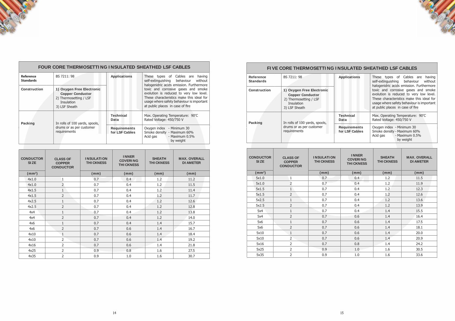
FOUR CORE THERMOSETTING INSULATED SHEATHED LSF CABLES
BS 7211: 98 Applications These types of Cables are having self-extinguishing behaviour without halogenidric acids emission. Furthermore toxic and corrosive gases and smoke evolution is reduced to very low level. These characteristics make this ideal for usage where safety behaviour is important at public places in case of fire
Max. Operating Temperature: 90 º C Rated Voltage: 450/750 V
Construction 1) Oxygen Free Electronic Copper Conductor 2) Thermosetting / LSF Insulation 3) LSF Sheath
Packing In rolls of 100 yards, spools, drums or as per customer requirements
Technical Data
Requirements for LSF Cables
Oxygen index - Minimum 30 Smoke density - Maximum 60% Acid gas - Maximum 0.5% by weight
CONDUCTOR SIZE
CLASS OF COPPER
CONDUCTOR
INSULATION THICKNESS
INNER COVERING THICKNESS
SHEATH THICKNESS
MAX. OVERALL DIAMETER
(mm 2 ) (mm) (mm) (mm) (mm)
4x1.0 1 0.7 0.4 1.2 11.2
4x1.0 2 0.7 0.4 1.2 11.5
4x1.5 1 0.7 0.4 1.2 11.4
4x1.5 2 0.7 0.4 1.2 11.7
4x2.5 1 0.7 0.4 1.2 12.6
4x2.5 2 0.7 0.4 1.2 12.8
4x4 1 0.7 0.4 1.2 13.8
4x4 2 0.7 0.4 1.2 14.0
4x6 1 0.7 0.4 1.4 15.7
4x6 2 0.7 0.6 1.4 16.7
4x10 1 0.7 0.6 1.4 18.4
4x10 2 0.7 0.6 1.4 19.2
4x16 2 0.7 0.6 1.4 21.8
4x25 2 0.9 0.8 1.6 27.5
4x35 2 0.9 1.0 1.6 30.7
FIVE CORE THERMOSETTING INSULATED SHEATHED LSF CABLES
Reference Standards
BS 7211: 98 Applications These types of Cables are having self-extinguishing behaviour without halogenidric acids emission. Furthermore toxic and corrosive gases and smoke evolution is reduced to very low level. These characteristics make this ideal for usage where safety behaviour is important at public places in case of fire
Max. Operating Temperature: 90 º C Rated Voltage: 450/750 V
Construction 1) Oxygen Free Electronic Copper Conductor 2) Thermosetting / LSF
Insulation 3) LSF Sheath
Packing In rolls of 100 yards, spools, drums or as per customer requirements
Technical Data
Requirements for LSF Cables
Oxygen index - Minimum 30 Smoke density - Maximum 60% Acid gas - Maximum 0.5% by weight
CONDUCTOR SIZE
CLASS OF COPPER
CONDUCTOR
INSULATION THICKNESS
INNER COVERING THICKNESS
SHEATH THICKNESS
MAX. OVERALL DIAMETER
(mm 2 ) (mm) (mm) (mm) (mm) 5x1.0 1 0.7 0.4 1.2 11.5
5x1.0 2 0.7 0.4 1.2 11.9
5x1.5 1 0.7 0.4 1.2 12.3
5x1.5 2 0.7 0.4 1.2 12.6
5x2.5 1 0.7 0.4 1.2 13.6
5x2.5 2 0.7 0.4 1.2 13.9
5x4 1 0.7 0.4 1.4 15.5
5x4 2 0.7 0.6 1.4 16.4
5x6 1 0.7 0.6 1.4 17.5
5x6 2 0.7 0.6 1.4 18.1
5x10 1 0.7 0.6 1.4 20.0
5x10 2 0.7 0.6 1.4 20.9
5x16 2 0.7 0.8 1.4 24.2
5x25 2 0.9 1.0 1.6 30.5
5x35 2 0.9 1.0 1.6 33.6

16
GENERAL CABLE TECHNICAL DATA & RATING FACTORS

17
Current carrying capacities at ambient temperature 30°C
Volt Drop Data
+ Volt drop for sizes 25mm 2 and 35mm 2 are based on total impedance 'z' only. For 'r' and 'x: data, lEE Wiring Regulations 16th Edition should be referred to.
NOTE : Data in the above table is based on lEE Wiring Regulations 16th Edition. The current carrying capacities of Heat Resistant PVC insulated cables are higher, please refer to Technical Department if data is required.
The tabulated current carrying capacities relate to continuous loading and are also known as the "full thermal ratings" implying that the cables will operate at their maximum conductor continuous temperature of 70°C. The data is extracted from lEE Wiring Regulations 16th Edition.
The tabulated current rating capacities also relate to installations where the overload protection is afforded by a fuse to BS 88 or BS 1361 or a miniature circuit breaker to BS 3871. Where the conductor is protected by a semi-enclosed fuse to BS 3036, the size of the conductor is to be such that its tabulated current carrying capacity is not less than the value of the fuse rating adjusted by multiplier 1.38 in addition to the correction factors for ambient temperature, thermal insulation and grouping. For details refer to clause 6.2 of Appendix 4 - lEE Wiring Regulations 16th Edition.
For a given cable run, to calculate the voltage drop (in mV), the tabulated value (mV/A/m) has to be multiplied by the cable route length in metres and the design current. For three-phase circuits the tabulated mV/A/m values relate to the line voltage. For cables of 16mm2 or less cross sectional area, the inductance can be ignored and mV/A/m values are based on resistance (r) only. For cables of cross sectional area greater than 16mm2, mV/A/m values based on resistance (r) and inductance (x) are significant. However for brevity, Table, for single core cables of sizes 25mm2 & 35mm2, list (mV/A/m) z values based on total impedance (z) only. Where the power factor of the A.C. load is widely different from the cable power factor, use of (mV/A/m) z values for calculating the volt drop may give a pessimistically high value. For detailed information, reference should be made to Appendix 4 of the lEE Wiring Regulations 16th Edition.
Table 1 Single Core PVC Insulated Non-Sheathed Cables - Cables
in conduit on a wall or ceiling or in trunking (Reference Method 3)
2
Current carrying
Capacities (amperes)
Volt Drop (mV/A/m)
Current carrying
capacities (amperes)
Volt Drop (mV/A/m)
3 or 4 three phase
ac
2 cables single phase ac
r x z
3 or 4 cables three phase ac
r x z
134 0.95 0.30 1.00 0.81 0.26 0.85
171 0.65 0.29 0.72 0.56 0.25 0.61
207 0.49 0.28 0.56 0.42 0.24 0.48
239 0.39 0.27 0.47 0.33 0.23 0.41
262 0.31 0.27 0.41 0.27 0.23 0.36
296 0.25 0.27 0.37 0.22 0.23 0.32
346 0.195 0.26 0.33 0.17 0.23 0.29
Conductor Cross
Sectional Area mm
1
1.5
2.5
4
6
10
16
+25
+35
394 0.160 0.26 0.31 0.14 0.23 0.27
467 0.130 0.26 0.29 0.12 0.22 0.25
2 cables single
phase ac or dc
13.5
17.5
24
32
41
57
76
101
125
3 or 4 cables three phase
ac
12
15.5
21
28
36
50
68
89
110
2 cables single
phase ac
44
29
18
11
7.3
4.4
2.8
1.8
1.3
3 or 4 cables three phase
ac
38
25
15
9.5
6.4
3.8
2.4
1.55
1.10 533 0.110 0.26 0.28 0.10 0.22 0.25
Conductor Cross
Sectional Area mm 2
50
70
95
120
150
185
240
300
400
500
630
2 cables single
phase ac or dc
151
192
232
269
300
341
400
458
546
626
720 611 0.094 0.25 0.27 0.08 0.22 0.24

18
Table 4 Conductor Resistance
Nominal conductor area
mm 2
Maximum diameter of conductor
mm
Maximum conductor
resistance per km at 20°C
ohm
Nominal conductor area
mm 2
Maximum diameter of conductor
mm
Maximum conductor
resistance per km at 20°C
ohm
1.5* 1.38 12.1 50 8.30 0.387
1.5 1.59 12.1 70 10.00 0.268
2.5* 1.78 7.41 95 11.70 0.193
2.5 2.01 7.41 120 13.15 0.153
150 14.55 0.124
4 2.55 4.61 185 16.30 0.0991
6 3.12 3.08 240 18.75 0.0754
10 4.05 1.83 300 21.00 0.0601
16 4.85 1.15 400 23.90 0.0470
25 6.15 0.727 500 28.40 0.0366
35 7.25 0.524 630 31.70 0.0283
Conductor short circuit ratings
Short circuit rating of copper conductor shall be calculated using following formula: Short circuit current I = kA/ √t Where,
k = 0.115 A = Cross sectional Area of conductor t = Duration in seconds
e.g. Short circuit rating of 300mm 2 Cu conductor for 1 sec. I = 0.115 x 300/ √1 = 34.5kA/sec.
The values of short circuit ratings derived from above formula based on the PVC insulated cable being fully loaded at the start of the short circuit conductor temperature of 70°C and final conductor temperature of 160°C.
Wiring Cable Installation
Wiring cables should be installed in accordance with lEE Wiring Regulations, 16th Edition or local installation regulations.
Minimum internal radius at bends:
CABLE DIAMETER Minimum internal radius
Up to 10 mm 3 x cable diameter
Exceeding 10 mm but less than 25 mm 4 x cable diameter
Exceeding 25 mm 6 x cable diameter
19
Thermal Insulation
Current ratings pertaining to cables or cable conduits totally surrounded by thermally insulating material are not included in the above tables. For such situations, in the absence of precise information, a rating factor of 0.5 may be applied to the appropriate current ratings.
For multi-core cables, current ratings of cables installed in thermally.insulated ceilings but in contact with a thermally conductive surface on one side are stated. For similar information applicable to single core cables, reference should be made to the lEE Wiring Regulations 16th Edition.
Table2 Rating Factors For ambient temperature other than 30°C, the tabulated
current ratings should be adjusted by factors as follows:
Ambient temperature °C 25 30 35 40 45 50 55 60 65 70 75 80 85
Overload protection afforded by device other than semi-enclosed fuse to BS 3036
Heat resisting PVC (90°C)* 1.03 1.0 0.97 0.94 0.91 0.87 0.84 0.80 0.76 0.71 0.61 0.5 0.35
Ordinary PVC (70°C) 1.03 1.0 0.94 0.87 0.79 0.71 0.61 0.50 035
Semi-enclosed fuse to BS 3036 (formerly coarse excess current protection)
Heat resisting PVC (90°C)* 1.03 1.0 0.97 0.94 0.91 0.87 0.84 0.80 0.76 0.72 0.68 0.63 0.49
Ordinary PVC (70°C) 1.03 1.0 0.97 0.94 0.91 0.87 0.84 0.69 0.48
These factors are applicable only to ratings in Table1.
Table 3 Correction factors for groups of cables
(Ref.IEE wiring regulation sixteenth edition)
Method of Installation Correction factor
Number of circuits or multicore cables 2 3 4 5 6 7 8 9 10 12 14 16 18 20
Enclosed in conductor trunking (Method 3 or 4) or bunched and clipped directly to non- metallic surface (Method 1)
0.80 0.70 0.65 0.60 0.57 0.54 0.52 0.50 0.48 0.45 0.43 0.41 0.39 0.38
Single layer clipped to a non-metallic surface (Method 1)
Touching 0.85 0.79 0.75 0.73 0.72 0.72 0.71 0.70 - - - - - -
Spaced* 0.94 0.90 0.90 0.90 0.90 0.90 0.90 0.90 0.90 0.90 0.90 0.90 0.90 0.90
Single layer multicore on a perforated metal cable tray, vertical or horizontal (Method 11)
Touching 0.86 0.81 0.77 0.75 0.74 0.73 0.73 0.72 0.71 0.70 - - - -
Spaced* 0.91 0.89 0.88 0.87 0.87 - - - - - - - - -
Single layer single core on a perforated metal cable tray. touching (Method 11)
Horizontal 0.90 0.85 - - - - - - - - - - - -
Vertical 0.85 - - - - - - - - - - - - -
Single layer Multicore touching on ladder supports (Method 13)
0.86 0.82 0.80 0.79 0.78 0.78 0.78 0.77 - - - - - -
* 'Spaced ' means a clearance between adjacent surfaces of at least one cable diameter (D). Where the horizontal clearances between adjacent cables exceeds 2D no correction factor need be applied. Notes: 1. The factors in the table are applicable to groups of cables all of one size. The value of current derived from application of the appropriate factors is the maximum continuous current to be carried by any of the cables in the group. 2. If, due to known operating conditions, a cable is expected to carry not more than 30% of its grouped rating, it may be ignored for the purpose of obtaining the rating factor for the rest of the group.

20 21

22


1
NUHAS OMAN – QUALITY & RELIABILITY.
INTRODUCTION Nuhas Oman LLC, an integral part of The Al Bahja Group of Companies, is a Quality producer of:
• HV, MV and LV Cables
• Enamelled Copper Wires
• Oxygen Free Continuous Cast Copper Wire Rods
• Drawn Copper Conductors
Our state-of-the-art manufacturing facilities with cutting edge technology ensure that our products meet with
highest quality standards. All our products utilize only OXYGEN FREE HIGH CONDUCTIVITY
ELECTRONIC GRADE Copper produced through the Outokompu UPCAST technology, producing minimum
99.99% pure copper with oxygen content less than 5 ppm. The usage of
Our range of World-class HV, MV and LV Cables includes Single & Multi Core Armoured and Un-armoured
Cables, Specialty, Control, Instrumentation and also LSF, FRLS, LSOH & Custom Cables to meet the
requirements of a broad spectrum of applications ranging from
The Cables are produced in compliance to the requirements of BS, IEC, VDE, ASTM, ICEA & UL
specifications. The by acclaimed independent international certifying agencies
confirming compliance to respective standards.
Nuhas that conform to relevant International standards and
Our quality cycle encompasses raw material and consumable sourcing, in-process production controls and
certification of finished goods prior to delivery. A well-equipped in-house quality assurance facility, manned by
qualified professionals from the industry, ensures that all products delivered meet stringent quality controls
and parameters. Our state-of-the-art laboratory is equipped to test as per relevant international standards as
also to individual customer specifications.
The company endeavours to cater to the domestic, regional and global markets while maintaining the sanctity
of our pristine environment.
is a continuing process at Nuhas Oman LLC and we at Nuhas Oman ceaselessly
strive to achieve product excellence through TOTAL QUALITY MANAGEMENT to provide the best value to
our customers.

2 3
XLPE INSULATED AND PVC SHEATHED ARMOURED CABLES
Sing
le C
ore
Two
Core
Th
ree
Core
Reference standards BS 5467 Construction 1) Oxygen free Electronic Copper Conductor 2) XLPE Insulation 3) Galvanized steel wire armour for multicore & aluminium wire for single core cables 4) PVC sheath
Applications For installation under ground, indoor ducts where mechanical damage is not expected. Suitable for comparatively higher operating tenperature with XLPE insulation. Technical data Max. Operating temperature: 90ºC Voltage: 600/1000 V
mm2 mm mm mm mm mm kg/km
Nominal Area of conductor
Thickness of Insulation
Nom thickness of
bedding
Armour wire Diameter
Nom thickness of oversheath
Approximate overall diameter
Approximate Cable Weight
50 1.0 0.8 0.9 1.5 16.5 690 70 1.1 0.8 1.25 1.5 19.0 950 95 1.1 0.8 1.25 1.6 21.0 1230 120 1.2 0.8 1.25 1.6 23.0 1490 150 1.4 1.0 1.6 1.7 26.0 1900 185 1.6 1.0 1.6 1.8 28.0 2320 240 1.7 1.0 1.6 1.8 31.0 2930 300 1.8 1.0 1.6 1.9 33.5 3580 400 2.0 1.2 2.0 2.0 38.0 4600 500 2.2 1.2 2.0 2.1 41.5 5680 630 2.4 1.2 2.0 2.2 46.0 7160 800 2.6 1.4 2.5 2.4 52.0 9315 1000 2.8 1.4 2.5 2.5 57.0 11490 1.5 0.7 0.8 0.9 1.3 12.0 255 2.5 0.7 0.8 0.9 1.4 13.5 305 4 0.7 0.8 0.9 1.4 14.5 360 6 0.7 0.8 0.9 1.4 15.5 430 10 0.7 0.8 0.9 1.5 17.5 580 16 0.7 0.8 1.25 1.5 20.0 835 25 0.9 0.8 1.25 1.6 19.5 995 35 0.9 1.0 1.6 1.7 22.5 1395 50 1.0 1.0 1.6 1.8 25.5 1735 70 1.1 1.0 1.6 1.9 28.5 2250 95 1.1 1.2 2.0 2.0 32.0 3055 120 1.2 1.2 2.0 2.1 34.5 3635 150 1.4 1.2 2.0 2.2 38.0 4360 185 1.6 1.4 2.5 2.4 42.0 5495 240 1.7 1.4 2.5 2.5 48.5 7000 300 1.8 1.6 2.5 2.6 53.0 8450 400 2.0 1.6 2.5 2.8 58.5 10335 1.5 0.7 0.8 0.9 1.3 12.5 290 2.5 0.7 0.8 0.9 1.4 14.0 350 4 0.7 0.8 0.9 1.4 15.0 420 6 0.7 0.8 0.9 1.4 16.0 505 10 0.7 0.8 1.25 1.5 19.5 800 16 0.7 0.8 1.25 1.6 21.0 1035 25 0.9 1.0 1.6 1.7 23.0 1465 35 0.9 1.0 1.6 1.8 25.5 1840 50 1.0 1.0 1.6 1.8 28.0 2305 70 1.1 1.0 1.6 1.9 31.5 3030 95 1.1 1.2 2.0 2.1 36.0 4160 120 1.2 1.2 2.0 2.2 40.0 5050 150 1.4 1.4 2.5 2.3 45.0 6415 185 1.6 1.4 2.5 2.4 48.0 7580 240 1.7 1.4 2.5 2.6 54.0 9565 300 1.8 1.6 2.5 2.7 60.0 11640 400 2.0 1.6 2.5 2.9 64.0 14290
TABLE 1
XLPE INSULATED AND PVC SHEATHED ARMOURED CABLES
Four
Cor
e Fi
ve C
ore
Reference standards BS 5467 Construction 1) Oxygen free Electronic Copper Conductor 2) XLPE Insulation 3) Galvanized steel wire armour for multicore & aluminium wire for single core cables 4) PVC sheath
Applications For installation under ground, indoor ducts where mechanical damage is not expected. Suitable for comparatively higher operating tenperature with XLPE insulation. Technical data Max. Operating temperature: 90ºC Voltage: 600/1000 V
mm2 mm mm mm mm mm kg/km
Nominal Area of conductor
Thickness of Insulation
Nom thickness of
bedding
Armour wire Diameter
Nom thickness of oversheath
Approximate overall diameter
Approximate Cable Weight
1.5 0.7 0.8 0.9 1.3 13.5 330 2.5 0.7 0.8 0.9 1.4 14.5 400 4 0.7 0.8 0.9 1.4 16.0 490 6 0.7 0.8 1.25 1.5 18.5 700 10 0.7 0.8 1.25 1.5 20.5 920 16 0.7 0.8 1.25 1.6 22.0 1240 25 0.9 1.0 1.6 1.7 26.0 1860 35 0.9 1.0 1.6 1.8 28.5 2330 50 1.0 1.0 1.6 1.9 31.5 2940 70 1.1 1.2 2.0 2.1 37.0 4150 95 1.1 1.2 2.0 2.2 40.5 5300 120 1.2 1.4 2.5 2.3 47.0 6940 150 1.4 1.4 2.5 2.4 50.0 8170 185 1.6 1.4 2.5 2.6 55.0 9850 240 1.7 1.6 2.5 2.7 62.0 12480 300 1.8 1.6 2.5 2.9 68.0 15100 400 2.0 1.8 3.15 3.2 78.0 19710 1.5 0.6 0.8 0.9 1.4 15.5 420 2.5 0.7 0.8 0.9 1.4 17.0 500 4 0.7 0.8 1.25 1.5 19.0 700 6 0.7 0.8 1.25 1.5 20.5 855 10 0.7 0.8 1.25 1.6 23.0 1170 16 0.7 1.0 1.6 1.7 26.0 1660 25 0.9 1.0 1.6 1.8 30.0 2285 35 0.9 1.0 1.6 1.9 33.0 2530 50 1.0 1.2 2.0 2.0 38.5 3920 70 1.1 1.2 2.0 2.2 43.5 5170
TABLE 1 (Contd.)

4 5
PVC INSULATED AND PVC SHEATHED ARMOURED CABLES
Sing
le C
ore
Two
Core
Th
ree
Core
Reference standards BS 6346 Construction 1) Oxygen free Electronic Copper Conductor 2) PVC Insulation 3) Galvanized steel wire armour for multicore & aluminium wire for single core cables 4) PVC sheath
Applications For installation under ground, indoor ducts where mechanical damage is not expected. Technical data Max. Operating temperature: 70ºC Voltage: 600/1000 V
mm2 mm mm mm mm mm kg/km
Nominal Area of conductor
Thickness of Insulation
Nom thickness of
bedding
Armour wire Diameter
Nom thickness of oversheath
Approximate overall diameter
Approximate Cable Weight
50 1.4 0.8 1.25 1.5 18.5 755 70 1.4 0.8 1.25 1.6 20.5 985 95 1.6 0.8 1.25 1.6 22.5 1285 120 1.6 1.0 1.6 1.7 25.5 1625 150 1.8 1.0 1.6 1.7 27.5 1950 185 2.0 1.0 1.6 1.8 29.5 2345 240 2.2 1.0 1.6 1.9 32.5 2975 300 2.4 1.0 1.6 1.9 35.0 3625 400 2.6 1.2 2.0 2.1 40.0 4655 500 2.8 1.2 2.0 2.1 43.5 5770 630 2.8 1.2 2.0 2.2 47.0 7250 800 2.8 1.4 2.5 2.4 53.0 9250 1000 3.0 1.4 2.5 2.5 58.0 11320 1.5 0.6 0.8 0.9 1.4 12.5 265 2.5 0.7 0.8 0.9 1.4 13.5 320 4 0.8 0.8 0.9 1.4 15.0 395 6 0.8 0.8 0.9 1.5 16.5 475 10 1.0 0.8 1.25 1.6 20.0 770 16 1.0 0.8 1.25 1.6 21.5 935 25 1.2 1.0 1.6 1.7 22.5 1225 35 1.2 1.0 1.6 1.8 24.5 1515 50 1.4 1.0 1.6 1.9 28.0 1900 70 1.4 1.0 1.6 1.9 30.0 2375 95 1.6 1.2 2.0 2.1 35.0 3300 120 1.6 1.2 2.0 2.2 37.0 3845 150 1.8 1.2 2.0 2.3 40.5 4590 185 2.0 1.4 2.5 2.4 44.0 5765 240 2.2 1.4 2.5 2.5 51.5 7350 300 2.4 1.6 2.5 2.7 56.5 8885 400 2.6 1.6 2.5 2.9 62.0 10850 1.5 0.6 0.8 0.9 1.4 12.5 295 2.5 0.7 0.8 0.9 1.4 14.0 370 4 0.8 0.8 0.9 1.4 15.5 465 6 0.8 0.8 1.25 1.5 18.0 650 10 1.0 0.8 1.25 1.6 21.0 925 16 1.0 0.8 1.25 1.6 23.0 1160 25 1.2 1.0 1.6 1.7 24.5 1595 35 1.2 1.0 1.6 1.8 27.5 1985 50 1.4 1.0 1.6 1.9 30.5 2520 70 1.4 1.2 2.0 2.0 35.0 3470 95 1.6 1.2 2.0 2.1 39.0 4470 120 1.6 1.2 2.0 2.2 42.5 5335 150 1.8 1.4 2.5 2.4 48.0 6805 185 2.0 1.4 2.5 2.5 50.5 7995 240 2.2 1.6 2.5 2.6 57.5 10150 300 2.4 1.6 2.5 2.8 63.5 12315 400 2.6 1.6 2.5 3.0 68.0 15000
TABLE 2
PVC INSULATED AND PVC SHEATHED ARMOURED CABLES
Four
Cor
e Fi
ve C
ore
Reference standards BS 6346 Construction 1) Oxygen free Electronic Copper Conductor 2) PVC Insulation 3) Galvanized steel wire armour for multicore & aluminium wire for single core cables 4) PVC sheath
Applications For installation under ground, indoor ducts where mechanical damage is not expected. Technical data Max. Operating temperature: 70ºC Voltage: 600/1000 V
mm2 mm mm mm mm mm kg/km
Nominal Area of conductor
Thickness of Insulation
Nom thickness of
bedding
Armour wire Diameter
Nom thickness of oversheath
Approximate overall diameter
Approximate Cable Weight
1.5 0.6 0.8 0.9 1.4 13.5 340 2.5 0.7 0.8 0.9 1.4 15.0 430 4 0.8 0.8 1.25 1.5 17.5 640 6 0.8 0.8 1.25 1.5 19.0 765 10 1.0 0.8 1.25 1.6 23.0 1100 16 1.0 1.0 1.6 1.7 26.0 1575 25 1.2 1.0 1.6 1.8 28.5 2045 35 1.2 1.0 1.6 1.9 31.0 2520 50 1.4 1.2 2.0 2.0 35.0 3405 70 1.4 1.2 2.0 2.1 39.0 4375 95 1.6 1.2 2.0 2.2 43.5 5675 120 1.6 1.4 2.5 2.4 50.0 7305 150 1.8 1.4 2.5 2.5 53.5 8630 185 2.0 1.6 2.5 2.6 58.5 10400 240 2.2 1.6 2.5 2.8 66.0 13130 300 2.4 1.6 2.5 3.0 72.0 15895 400 2.6 1.8 3.15 3.3 82.0 20655 1.5 0.6 0.8 0.9 1.4 14.5 380 2.5 0.7 0.8 0.9 1.5 16.0 495 4 0.8 0.8 1.25 1.5 19.0 720 6 0.8 0.8 1.25 1.6 20.5 885 10 1.0 1.0 1.6 1.7 26.0 1450 16 1.0 1.0 1.6 1.7 28.0 1845 25 1.2 1.0 1.6 1.9 32.5 2530 35 1.2 1.0 1.6 1.9 35.0 2750 50 1.4 1.2 2.0 2.1 41.0 4280 70 1.4 1.2 2.0 2.2 46.0 5495
TABLE 2 (Contd.)

6 7
XLPE INSULATED AND LSF SHEATHED ARMOURED CABLES
Sing
le C
ore
Two
Core
Th
ree
Core
Reference standards BS 6724 Construction 1) Oxygen free Electronic Copper Conductor 2) XLPE Insulation 3) Galvanized steel wire armour for multicore & aluminium wire for single core cables 4) LSF sheath
Applications These cables have self-extinguishing behaviour without halogen acid gas emission. Furthermore toxic and corrosive gases and smoke emission is reduced to very low level. These characteristics make the cable ideal for use where safety behaviour is important as at public places in case of fire. Technical data Max. Operating temperature: 90ºC Voltage: 600/1000 V
mm2 mm mm mm mm mm kg/km
Nominal Area of conductor
Thickness of Insulation
Nom thickness of
bedding
Armour wire Diameter
Nom thickness of oversheath
Approximate overall diameter
Approximate Cable Weight
50 1.0 0.8 0.9 1.5 17.0 705 70 1.1 0.8 1.25 1.5 19.5 965 95 1.1 0.8 1.25 1.6 21.5 1250 120 1.2 0.8 1.25 1.6 23.5 1510 150 1.4 1.0 1.6 1.7 26.5 1925 185 1.6 1.0 1.6 1.8 29.0 2345 240 1.7 1.0 1.6 1.8 32.0 2960 300 1.8 1.0 1.6 1.9 34.5 3610 400 2.0 1.2 2.0 2.0 39.5 4635 500 2.2 1.2 2.0 2.1 43.0 5715 630 2.4 1.2 2.0 2.2 47.5 7200 800 2.6 1.4 2.5 2.4 54.0 9355 1000 2.8 1.4 2.5 2.5 59.0 11525 1.5 0.7 0.8 0.9 1.3 11.5 260 2.5 0.7 0.8 0.9 1.4 13.0 310 4 0.7 0.8 0.9 1.4 14.0 370 6 0.7 0.8 0.9 1.4 15.5 440 10 0.7 0.8 0.9 1.5 17.5 590 16 0.7 0.8 1.25 1.5 19.5 850 25 0.9 0.8 1.25 1.6 19.5 1010 35 0.9 1.0 1.6 1.7 22.5 1410 50 1.0 1.0 1.6 1.8 25.0 1755 70 1.1 1.0 1.6 1.9 28.0 2270 95 1.1 1.2 2.0 2.0 32.0 3080 120 1.2 1.2 2.0 2.1 35.0 3660 150 1.4 1.2 2.0 2.2 38.5 4385 185 1.6 1.4 2.5 2.4 43.5 5520 240 1.7 1.4 2.5 2.5 48.0 7025 300 1.8 1.6 2.5 2.6 52.0 8470 400 2.0 1.6 2.5 2.8 57.5 10450 1.5 0.7 0.8 0.9 1.3 12.0 295 2.5 0.7 0.8 0.9 1.4 13.5 360 4 0.7 0.8 0.9 1.4 15.0 430 6 0.7 0.8 0.9 1.4 16.0 515 10 0.7 0.8 1.25 1.5 19.0 815 16 0.7 0.8 1.25 1.6 21.0 1050 25 0.9 1.0 1.6 1.7 23.0 1485 35 0.9 1.0 1.6 1.8 25.0 1860 50 1.0 1.0 1.6 1.8 27.5 2330 70 1.1 1.0 1.6 1.9 31.5 3055 95 1.1 1.2 2.0 2.1 36.0 4190 120 1.2 1.2 2.0 2.2 39.5 5085 150 1.4 1.4 2.5 2.3 44.5 6450 185 1.6 1.4 2.5 2.4 48.5 7615 240 1.7 1.4 2.5 2.6 53.5 9595 300 1.8 1.6 2.5 2.7 58.5 11665 400 2.0 1.6 2.5 2.9 65.0 14305
TABLE 3
XLPE INSULATED AND LSF SHEATHED ARMOURED CABLES
Four
Cor
e Fi
ve C
ore
Reference standards BS 6724 Construction 1) Oxygen free Electronic Copper Conductor 2) XLPE Insulation 3) Galvanized steel wire armour for multicore & aluminium wire for single core cables 4) LSF sheath
Applications These cables have self-extinguishing behaviour without halogen acid gas emission. Furthermore toxic and corrosive gases and smoke emission is reduced to very low level. These characteristics make the cable ideal for use where safety behaviour is important as at public places in case of fire. Technical data Max. Operating temperature: 90ºC Voltage: 600/1000 V
mm2 mm mm mm mm mm kg/km
Nominal Area of conductor
Thickness of Insulation
Nom thickness of
bedding
Armour wire Diameter
Nom thickness of oversheath
Approximate overall diameter
Approximate Cable Weight
1.5 0.7 0.8 0.9 1.3 13.0 340 2.5 0.7 0.8 0.9 1.4 14.5 410 4 0.7 0.8 0.9 1.4 16.0 500 6 0.7 0.8 1.25 1.5 18.0 710 10 0.7 0.8 1.25 1.5 20.5 935 16 0.7 0.8 1.25 1.6 22.5 1255 25 0.9 1.0 1.6 1.7 25.5 1885 35 0.9 1.0 1.6 1.8 27.5 2355 50 1.0 1.0 1.6 1.9 31.0 2970 70 1.1 1.2 2.0 2.1 36.5 4185 95 1.1 1.2 2.0 2.2 40.5 5340 120 1.2 1.4 2.5 2.3 46.0 6985 150 1.4 1.4 2.5 2.4 50.0 8215 185 1.6 1.4 2.5 2.6 55.0 9890 240 1.7 1.6 2.5 2.7 61.5 12520 300 1.8 1.6 2.5 2.9 67.0 15285 400 2.0 1.8 3.15 3.2 76.5 19930 1.5 0.6 0.8 0.9 1.4 14.0 430 2.5 0.7 0.8 0.9 1.4 15.5 510 4 0.7 0.8 1.25 1.5 17.0 715 6 0.7 0.8 1.25 1.5 19.5 870 10 0.7 0.8 1.25 1.6 22.0 1190 16 0.7 1.0 1.6 1.7 26.0 1680 25 0.9 1.0 1.6 1.8 30.5 2315 35 0.9 1.0 1.6 1.9 34.0 2560 50 1.0 1.2 2.0 2.0 39.5 3960 70 1.1 1.2 2.0 2.2 45.0 5215
TABLE 3 (Contd.)

8 9
XLPE INSULATED AND PVC SHEATHED UN - ARMOURED CABLES
Sing
le C
ore
Two
Core
Th
ree
Core
Reference standards Single core cables -BS7889/IEC60502-1 Multicore cables - IEC 60502-1 Construction 1) Oxygen free Electronic Copper Conductor 2) XLPE Insulation 3) PVC sheath
Applications For fixed installation in industrial areas, buildings and similar applications but not for direct burial in the ground. Suitable for comparatively higher temperature with XLPE insulation. Technical data Max. Operating temperature: 90ºC Voltage: 600/1000 V
mm2 mm mm mm kg/km
Nominal Area of conductor
Thickness of Insulation
Thickness of oversheath
Approximate overall diameter
Approximate Cable Weight
50 1.0 1.4 14.0 520 70 1.1 1.4 16.0 720 95 1.1 1.5 18.0 975 120 1.2 1.5 20.0 1215 150 1.4 1.6 22.0 1495 185 1.6 1.6 24.5 1830 240 1.7 1.7 27.5 2375 300 1.8 1.8 30.5 2955 400 2.0 1.9 34.0 3755 500 2.2 2.0 38.0 4805 630 2.4 2.2 42.5 6230 800 2.6 2.3 47.5 7940 1000 2.8 2.4 53.0 9855 1.5 0.7 1.8 10.0 110 2.5 0.7 1.8 11.0 135 4 0.7 1.8 12.0 170 6 0.7 1.8 13.0 220 10 0.7 1.8 15.0 325 16 0.7 1.8 16.5 450 25 0.9 1.8 16.0 615 35 0.9 1.8 18.0 810 50 1.0 1.8 20.5 1060 70 1.1 1.8 23.0 1465 95 1.1 2.0 26.0 1985 120 1.2 2.1 28.5 2470 150 1.4 2.2 32.0 3045 185 1.6 2.3 34.5 3730 240 1.7 2.5 41.5 4880 300 1.8 2.7 45.5 6075 400 2.0 2.9 51.0 7715 1.5 0.7 1.8 10.5 130 2.5 0.7 1.8 11.5 165 4 0.7 1.8 12.5 220 6 0.7 1.8 14.0 285 10 0.7 1.8 16.0 435 16 0.7 1.8 17.5 615 25 0.9 1.8 18.0 880 35 0.9 1.8 20.5 1165 50 1.0 1.8 23.5 1535 70 1.1 1.9 26.5 2145 95 1.1 2.0 30.0 2895 120 1.2 2.1 33.5 3630 150 1.4 2.3 37.5 4480 185 1.6 2.4 40.5 5505 240 1.7 2.6 46.5 7165 300 1.8 2.8 52.5 8930 400 2.0 3.1 57.0 11365
TABLE 4
XLPE INSULATED AND PVC SHEATHED UN - ARMOURED CABLES
Four
Cor
e Fi
ve C
ore
Reference standards Single core cables -BS7889/IEC60502-1 Multicore cables - IEC 60502-1 Construction 1) Oxygen free Electronic Copper Conductor 2) XLPE Insulation 3) PVC sheath
Applications For fixed installation in industrial areas, buildings and similar applications but not for direct burial in the ground. Suitable for comparatively higher temperature with XLPE insulation. Technical data Max. Operating temperature: 90ºC Voltage: 600/1000 V
mm2 mm mm mm kg/km
Nominal Area of conductor
Thickness of Insulation
Thickness of oversheath
Approximate overall diameter
Approximate Cable Weight
1.5 0.7 1.8 11.5 155 2.5 0.7 1.8 12.5 200 4 0.7 1.8 13.5 270 6 0.7 1.8 15.0 355 10 0.7 1.8 17.5 545 16 0.7 1.8 19.0 795 25 0.9 1.8 22.0 1165 35 0.9 1.8 23.5 1530 50 1.0 1.9 26.0 2030 70 1.1 2.0 30.5 2840 95 1.1 2.1 34.0 3830 120 1.2 2.3 39.5 4825 150 1.4 2.4 43.0 5925 185 1.6 2.6 48.0 7320 240 1.7 2.8 55.0 9520 300 1.8 3.0 60.5 11860 400 2.0 3.3 69.0 15135 1.5 0.7 1.8 12.0 175 2.5 0.7 1.8 13.0 230 4 0.7 1.8 14.5 315 6 0.7 1.8 16.0 420 10 0.7 1.8 18.5 655 16 0.7 1.8 20.5 965 25 0.9 1.8 24.5 1450 35 0.9 1.8 27.5 1585 50 1.0 2.0 31.5 2560 70 1.1 2.1 36.5 3570
TABLE 4 (Contd.)
10 11
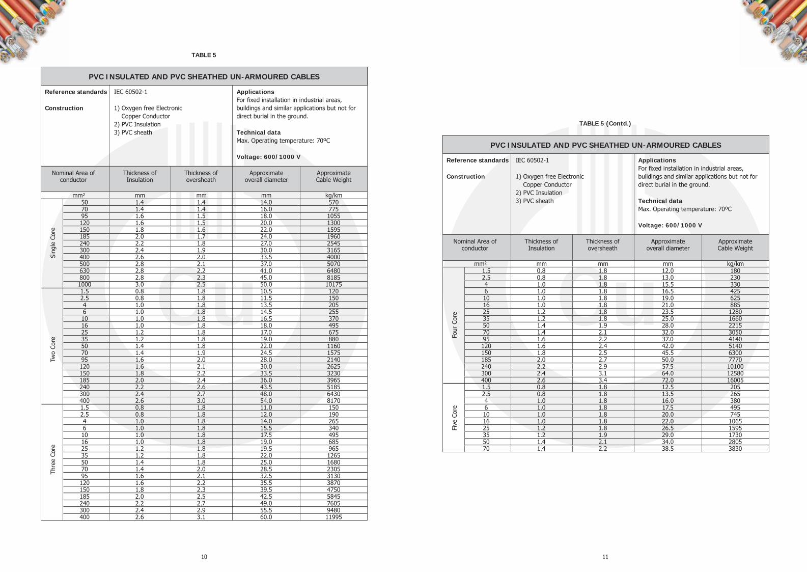
PVC INSULATED AND PVC SHEATHED UN-ARMOURED CABLES
Sing
le C
ore
Reference standards IEC 60502-1 Construction 1) Oxygen free Electronic Copper Conductor 2) PVC Insulation 3) PVC sheath
Applications For fixed installation in industrial areas, buildings and similar applications but not for direct burial in the ground. Technical data Max. Operating temperature: 70ºC Voltage: 600/1000 V
mm2 mm mm mm kg/km
Nominal Area of conductor
Thickness of Insulation
Thickness of oversheath
Approximate overall diameter
Approximate Cable Weight
50 1.4 1.4 14.0 570 70 1.4 1.4 16.0 775 95 1.6 1.5 18.0 1055 120 1.6 1.5 20.0 1300 150 1.8 1.6 22.0 1595 185 2.0 1.7 24.0 1960 240 2.2 1.8 27.0 2545 300 2.4 1.9 30.0 3165 400 2.6 2.0 33.5 4000 500 2.8 2.1 37.0 5070 630 2.8 2.2 41.0 6480 800 2.8 2.3 45.0 8185 1000 3.0 2.5 50.0 10175 1.5 0.8 1.8 10.5 120 2.5 0.8 1.8 11.5 150 4 1.0 1.8 13.5 205 6 1.0 1.8 14.5 255 10 1.0 1.8 16.5 370 16 1.0 1.8 18.0 495 25 1.2 1.8 17.0 675 35 1.2 1.8 19.0 880 50 1.4 1.8 22.0 1160 70 1.4 1.9 24.5 1575 95 1.6 2.0 28.0 2140 120 1.6 2.1 30.0 2625 150 1.8 2.2 33.5 3230 185 2.0 2.4 36.0 3965 240 2.2 2.6 43.5 5185 300 2.4 2.7 48.0 6430 400 2.6 3.0 54.0 8170 1.5 0.8 1.8 11.0 150 2.5 0.8 1.8 12.0 190 4 1.0 1.8 14.0 265 6 1.0 1.8 15.5 340 10 1.0 1.8 17.5 495 16 1.0 1.8 19.0 685 25 1.2 1.8 19.5 965 35 1.2 1.8 22.0 1265 50 1.4 1.8 25.0 1680 70 1.4 2.0 28.5 2305 95 1.6 2.1 32.5 3130 120 1.6 2.2 35.5 3870 150 1.8 2.3 39.5 4750 185 2.0 2.5 42.5 5845 240 2.2 2.7 49.0 7605 300 2.4 2.9 55.5 9480 400 2.6 3.1 60.0 11995
Two
Core
Th
ree
Core
TABLE 5
1.5 0.8 1.8 12.0 180 2.5 0.8 1.8 13.0 230 4 1.0 1.8 15.5 330 6 1.0 1.8 16.5 425 10 1.0 1.8 19.0 625 16 1.0 1.8 21.0 885 25 1.2 1.8 23.5 1280 35 1.2 1.8 25.0 1660 50 1.4 1.9 28.0 2215 70 1.4 2.1 32.0 3050 95 1.6 2.2 37.0 4140 120 1.6 2.4 42.0 5140 150 1.8 2.5 45.5 6300 185 2.0 2.7 50.0 7770 240 2.2 2.9 57.5 10100 300 2.4 3.1 64.0 12580 400 2.6 3.4 72.0 16005 1.5 0.8 1.8 12.5 205 2.5 0.8 1.8 13.5 265 4 1.0 1.8 16.0 380 6 1.0 1.8 17.5 495 10 1.0 1.8 20.0 745 16 1.0 1.8 22.0 1065 25 1.2 1.8 26.5 1595 35 1.2 1.9 29.0 1730 50 1.4 2.1 34.0 2805 70 1.4 2.2 38.5 3830
PVC INSULATED AND PVC SHEATHED UN-ARMOURED CABLES
Reference standards IEC 60502-1 Construction 1) Oxygen free Electronic Copper Conductor 2) PVC Insulation 3) PVC sheath
Applications For fixed installation in industrial areas, buildings and similar applications but not for direct burial in the ground. Technical data Max. Operating temperature: 70ºC Voltage: 600/1000 V
mm2 mm mm mm kg/km
Nominal Area of conductor
Thickness of Insulation
Thickness of oversheath
Approximate overall diameter
Approximate Cable Weight
Five
Cor
e Fo
ur C
ore
TABLE 5 (Contd.)

12 13
ARMOURED CONTROL CABLES - XLPE INSULATION
Reference standards BS 5467 Construction 1) Oxygen free Electronic Copper Conductor 2) XLPE Insulation 3) Galvanized steel wire armour 4) PVC sheath
Applications For installation underground, indoor ducts and in open where mechanical protection is required or for higher tensile stresses during installation and operation. Suitable for comparatively higher operating tenperature with XLPE insulation. Technical data Max. Operating temperature: 90ºC Voltage: 600/1000 V
nos mm2 mm mm mm mm mm kg/km 7 1.5 0.6 0.8 0.9 1.4 15.0 455 12 1.5 0.6 0.8 1.25 1.5 19.0 725 19 1.5 0.6 0.8 1.25 1.6 21.5 965 27 1.5 0.6 1.0 1.6 1.7 26.0 1380 37 1.5 0.6 1.0 1.6 1.7 28.5 1675 48 1.5 0.6 1.0 1.6 1.8 32.0 2080 7 2.5 0.7 0.8 0.9 1.4 16.5 590 12 2.5 0.7 0.8 1.25 1.6 22.0 965 19 2.5 0.7 1.0 1.6 1.7 26.0 1465 27 2.5 0.7 1.0 1.6 1.8 30.0 1845 37 2.5 0.7 1.0 1.6 1.8 33.0 2275 48 2.5 0.7 1.2 2.0 2.0 38.5 3080 7 4.0 0.7 0.8 1.25 1.5 19.5 850 12 4.0 0.7 1.0 1.6 1.6 25.0 1405 19 4.0 0.7 1.0 1.6 1.7 29.0 1850 27 4.0 0.7 1.0 1.6 1.9 34.0 2385 37 4.0 0.7 1.2 2.0 2.0 38.5 3360 48 4.0 0.7 1.2 2.0 2.1 43.5 4053
Thickness of Insulation
Nom thickness of
bedding
Armour wire Diameter
Nom thickness of oversheath
Approximate overall diameter
Approximate Cable Weight
No. of cores
Area of conductor
TABLE 6
ARMOURED CONTROL CABLES - PVC INSULATION
Reference standards BS 6346 Construction 1) Oxygen free Electronic Copper Conductor 2) PVC Insulation 3) Galvanized steel wire armour 4) PVC sheath
Applications For installation underground, indoor ducts and in open where mechanical protection is required or for higher tensile stresses during installation and operation Technical data Max. Operating temperature: 70ºC Voltage: 600/1000 V
nos mm2 mm mm mm mm mm kg/km 7 1.5 0.6 0.8 0.9 1.4 15.0 470 12 1.5 0.6 0.8 1.25 1.5 19.0 815 19 1.5 0.6 0.8 1.25 1.6 21.5 1100 27 1.5 0.6 1.0 1.6 1.7 26.0 1625 37 1.5 0.6 1.0 1.6 1.8 28.5 1910 48 1.5 0.6 1.0 1.6 1.9 32.5 2320 7 2.5 0.7 0.8 1.25 1.5 17.5 735 12 2.5 0.7 0.8 1.25 1.6 22.0 1070 19 2.5 0.7 1.0 1.6 1.7 26.0 1625 27 2.5 0.7 1.0 1.6 1.8 30.0 2080 37 2.5 0.7 1.0 1.6 1.9 33.5 2645 48 2.5 0.7 1.2 2.0 2.1 39.0 3495 7 4.0 0.8 0.8 1.25 1.6 20.0 920 12 4.0 0.8 1.0 1.6 1.7 26.5 1555 19 4.0 0.8 1.0 1.6 1.8 30.0 2035 27 4.0 0.8 1.2 2.0 2.0 36.5 2995 37 4.0 0.8 1.2 2.0 2.1 40.0 3690 48 4.0 0.8 1.2 2.0 2.2 45.5 4495
Thickness of Insulation
Nom thickness of
bedding
Armour wire Diameter
Nom thickness of oversheath
Approximate overall diameter
Approximate Cable Weight
No. of cores
Area of conductor
TABLE 7

14 15
UN-ARMOURED CONTROL CABLES - XLPE INSULATION
Reference standards IEC 60502-1 Construction 1) Oxygen free Electronic Copper Conductor 2) XLPE Insulation 3) PVC sheath
Applications For fixed installation in industrial areas, buildings and similar applications but not for direct burial in the ground. Suitable for comparatively higher temperature with XLPE insulation. Technical data Max. Operating temperature: 90ºC Voltage: 600/1000 V
nos mm2 mm mm mm kg/km 7 1.5 0.7 1.8 13.0 230 10 1.5 0.7 1.8 16.5 315 12 1.5 0.7 1.8 17.0 355 19 1.5 0.7 1.8 19.5 510 24 1.5 0.7 1.8 22.5 630 27 1.5 0.7 1.8 23.0 690 30 1.5 0.7 1.8 24.0 755 37 1.5 0.7 1.8 26.0 900 48 1.5 0.7 1.8 29.5 1135 7 2.5 0.7 1.8 14.5 305 10 2.5 0.7 1.8 18.0 420 12 2.5 0.7 1.8 18.5 480 19 2.5 0.7 1.8 21.5 705 24 2.5 0.7 1.8 25.0 875 27 2.5 0.7 1.8 25.5 960 30 2.5 0.7 1.8 26.5 1055 37 2.5 0.7 1.8 28.5 1265 48 2.5 0.7 1.9 33.0 1625 7 4 0.7 1.8 16.0 420 10 4 0.7 1.8 20.0 580 12 4 0.7 1.8 20.5 670 19 4 0.7 1.8 24.0 995 24 4 0.7 1.8 28.0 1240 27 4 0.7 1.8 29.0 1370 30 4 0.7 1.9 30.0 1520 37 4 0.7 1.9 32.5 1840 48 4 0.7 2.1 37.5 2380
Thickness of Insulation
Thickness of oversheath
Approximate overall diameter
Approximate Cable Weight
No. of cores
Area of conductor
ARMOURED CONTROL LSF CABLES - THERMOSETTING INSULATION
Reference standards BS 6724 Construction 1) Oxygen free Electronic Copper Conductor 2) Thermosetting Insulation 3) Galvanized steel wire armour 4) LSF sheath
Applications These cables have self-extinguishing behaviour without halogen acid gas emission. Furthermore toxic and corrosive gases and smoke emission is reduced to very low level. These characteristics make the cable ideal for use where safety behaviour is important as at public places in case of fire. Technical data Max. Operating temperature: 90ºC Voltage: 600/1000 V
nos mm2 mm mm mm mm mm kg/km 7 1.5 0.6 0.8 0.9 1.4 15.0 465 12 1.5 0.6 0.8 1.25 1.5 19.0 740 19 1.5 0.6 0.8 1.25 1.6 21.5 980 27 1.5 0.6 1.0 1.6 1.7 26.0 1405 37 1.5 0.6 1.0 1.6 1.7 28.5 1705 48 1.5 0.6 1.0 1.6 1.8 32.0 2115 7 2.5 0.7 0.8 0.9 1.4 16.5 600 12 2.5 0.7 0.8 1.25 1.6 22.0 980 19 2.5 0.7 1.0 1.6 1.7 26.0 1490 27 2.5 0.7 1.0 1.6 1.8 30.0 1875 37 2.5 0.7 1.0 1.6 1.8 33.0 2310 48 2.5 0.7 1.2 2.0 2.0 38.5 3130 7 4.0 0.7 0.8 1.25 1.5 19.5 865 12 4.0 0.7 1.0 1.6 1.6 25.0 1430 19 4.0 0.7 1.0 1.6 1.7 29.0 1880 27 4.0 0.7 1.0 1.6 1.9 34.0 2425 37 4.0 0.7 1.2 2.0 2.0 38.5 3415 48 4.0 0.7 1.2 2.0 2.1 43.5 4115
Thickness of Insulation
Nom thickness of
bedding
Armour wire Diameter
Nom thickness of oversheath
Approximate overall diameter
Approximate Cable Weight
No. of cores
Area of conductor
TABLE 8
TABLE 9

16 17
UN-ARMOURED CONTROL CABLES - PVC INSULATION
Reference standards IEC 60502-1 Construction 1) Oxygen free Electronic Copper Conductor 2) PVC Insulation 3) PVC sheath
Applications For fixed installation in industrial areas, buildings and similar applications but not for direct burial in the ground. Technical data Max. Operating temperature: 70ºC Voltage: 600/1000 V
nos mm2 mm mm mm kg/km 7 1.5 0.8 1.8 14.0 275 10 1.5 0.8 1.8 17.0 375 12 1.5 0.8 1.8 18.0 425 19 1.5 0.8 1.8 20.5 615 24 1.5 0.8 1.8 24.0 765 27 1.5 0.8 1.8 24.5 840 30 1.5 0.8 1.8 25.5 920 37 1.5 0.8 1.8 27.5 1105 48 1.5 0.8 1.9 31.5 1415 7 2.5 0.8 1.8 15.0 355 10 2.5 0.8 1.8 19.0 490 12 2.5 0.8 1.8 19.5 560 19 2.5 0.8 1.8 22.5 825 24 2.5 0.8 1.8 26.5 1030 27 2.5 0.8 1.8 27.0 1135 30 2.5 0.8 1.8 28.0 1245 37 2.5 0.8 1.9 30.5 1515 48 2.5 0.8 2.0 35.0 1945 7 4 1.0 1.8 18.0 520 10 4 1.0 1.8 22.5 725 12 4 1.0 1.8 23.5 840 19 4 1.0 1.8 27.5 1250 24 4 1.0 1.9 32.5 1575 27 4 1.0 2.0 33.5 1760 30 4 1.0 2.0 34.5 1935 37 4 1.0 2.1 37.5 2355 48 4 1.0 2.3 43.5 3045
Thickness of Insulation
Thickness of oversheath
Approximate overall diameter
Approximate Cable Weight
No. of cores
Area of conductor
TABLE 10
Maximum DC resistance and Construction of conductor as per BS EN 60228
1.5 12.1 7 6 - 2.5 7.41 7 6 - 4 4.61 7 6 - 6 3.08 7 6 - 10 1.83 7 6 - 16 1.15 7 6 - 25 0.727 7 6 6 35 0.524 7 6 6 50 0.387 19 6 6 70 0.268 19 12 12 95 0.193 19 15 15 120 0.153 37 18 18 150 0.124 37 18 18 185 0.0991 37 30 30 240 0.0754 37 34 34 300 0.0601 61 34 34 400 0.0470 61 53 53 500 0.0366 61 53 - 630 0.0283 91 53 - 800 0.0221 91 53 - 1000 0.0176 91 53 -
Nominal conductor area mm²
Resistance of conductor at 20˚C
per km (Ω) Circular Circular
compacted Shaped
Minimum number of wires in conductor
Plain annealed copper stranded class 2 conductor
TABLE 11
18
GENERAL CABLE TECHNICAL DATA & RATING FACTORS
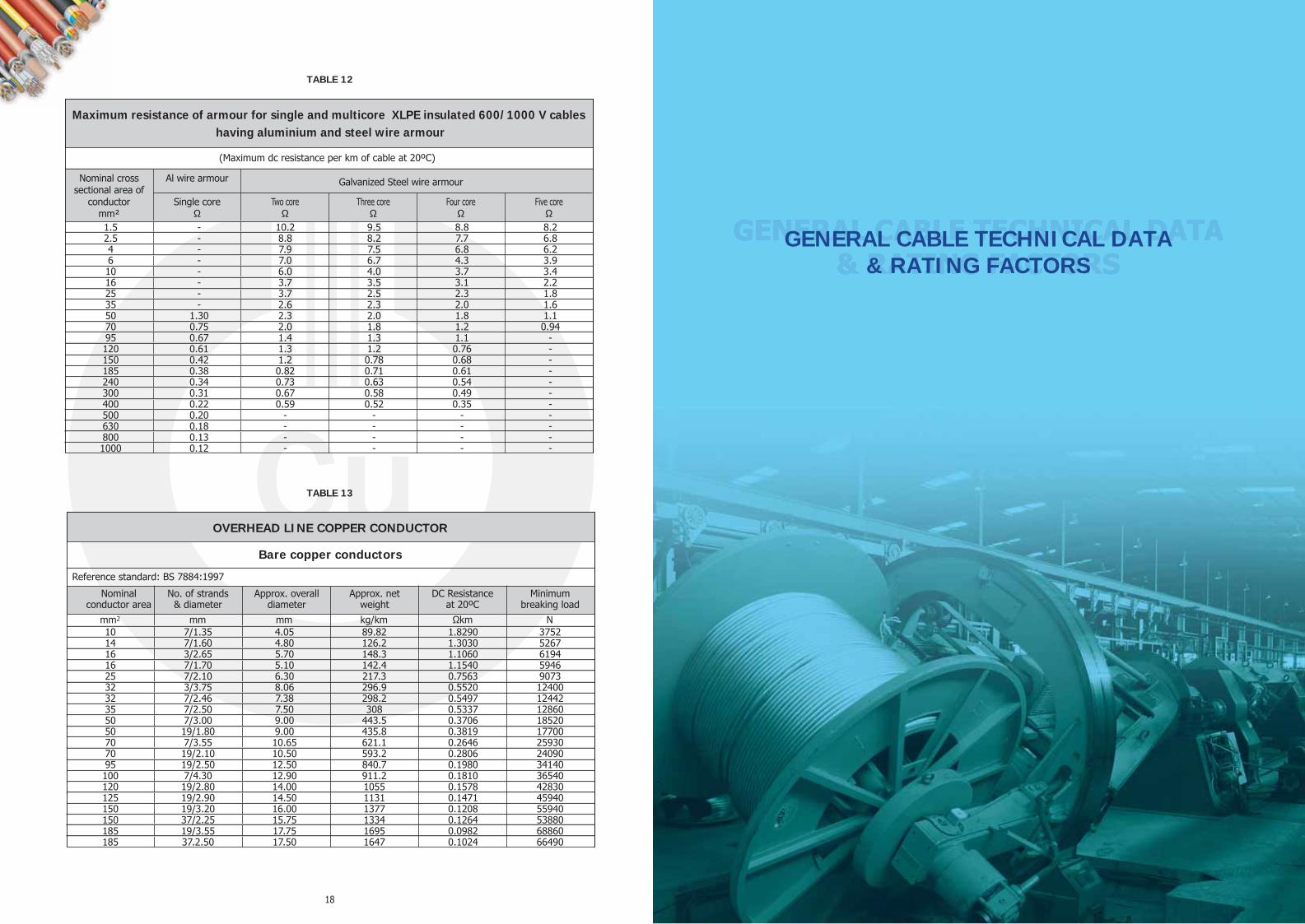
Maximum resistance of armour for single and multicore XLPE insulated 600/1000 V cables having aluminium and steel wire armour
1.5 - 10.2 9.5 8.8 8.2 2.5 - 8.8 8.2 7.7 6.8 4 - 7.9 7.5 6.8 6.2 6 - 7.0 6.7 4.3 3.9 10 - 6.0 4.0 3.7 3.4 16 - 3.7 3.5 3.1 2.2 25 - 3.7 2.5 2.3 1.8 35 - 2.6 2.3 2.0 1.6 50 1.30 2.3 2.0 1.8 1.1 70 0.75 2.0 1.8 1.2 0.94 95 0.67 1.4 1.3 1.1 - 120 0.61 1.3 1.2 0.76 - 150 0.42 1.2 0.78 0.68 - 185 0.38 0.82 0.71 0.61 - 240 0.34 0.73 0.63 0.54 - 300 0.31 0.67 0.58 0.49 - 400 0.22 0.59 0.52 0.35 - 500 0.20 - - - - 630 0.18 - - - - 800 0.13 - - - - 1000 0.12 - - - -
Galvanized Steel wire armour
(Maximum dc resistance per km of cable at 20ºC)
Nominal cross sectional area of
conductor mm²
Al wire armour
Single core Ω
Two core Three core Four core Five core Ω Ω Ω Ω
OVERHEAD LINE COPPER CONDUCTOR
10 7/1.35 4.05 89.82 1.8290 3752 14 7/1.60 4.80 126.2 1.3030 5267 16 3/2.65 5.70 148.3 1.1060 6194 16 7/1.70 5.10 142.4 1.1540 5946 25 7/2.10 6.30 217.3 0.7563 9073 32 3/3.75 8.06 296.9 0.5520 12400 32 7/2.46 7.38 298.2 0.5497 12442 35 7/2.50 7.50 308 0.5337 12860 50 7/3.00 9.00 443.5 0.3706 18520 50 19/1.80 9.00 435.8 0.3819 17700 70 7/3.55 10.65 621.1 0.2646 25930 70 19/2.10 10.50 593.2 0.2806 24090 95 19/2.50 12.50 840.7 0.1980 34140 100 7/4.30 12.90 911.2 0.1810 36540 120 19/2.80 14.00 1055 0.1578 42830 125 19/2.90 14.50 1131 0.1471 45940 150 19/3.20 16.00 1377 0.1208 55940 150 37/2.25 15.75 1334 0.1264 53880 185 19/3.55 17.75 1695 0.0982 68860 185 37.2.50 17.50 1647 0.1024 66490
Bare copper conductors
mm2 mm mm kg/km Ωkm N
Minimum breaking load
Nominal conductor area
No. of strands & diameter
Approx. overall diameter
Approx. net weight
DC Resistance at 20ºC
Reference standard: BS 7884:1997
TABLE 12
TABLE 13

21
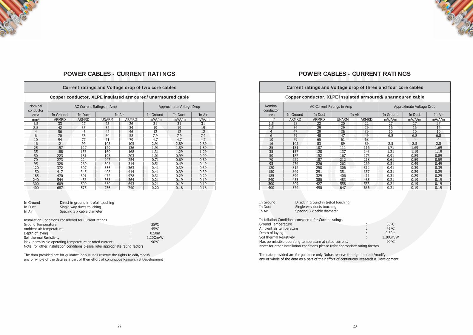
Current ratings and Voltage drop of single core cables
50 199 200 185 192 0.88 0.92 0.86 70 244 240 236 245 0.63 0.69 0.61 95 292 282 292 300 0.48 0.55 0.46 120 332 316 342 349 0.4 0.47 0.38 150 371 342 394 401 0.34 0.42 0.32 185 417 377 457 461 0.29 0.38 0.27 240 480 421 546 543 0.25 0.34 0.23 300 536 459 632 618 0.22 0.31 0.2 400 594 488 736 706 0.21 0.29 0.19 500 658 527 852 799 0.19 0.27 0.17 630 723 568 984 900 0.18 0.25 0.16 800 764 593 1118 978 0.18 0.24 0.16 1000 810 630 1247 1061 0.17 0.23 0.15
Nominal conductor
area
Copper conductor XLPE insulated armoured/unarmoured cable
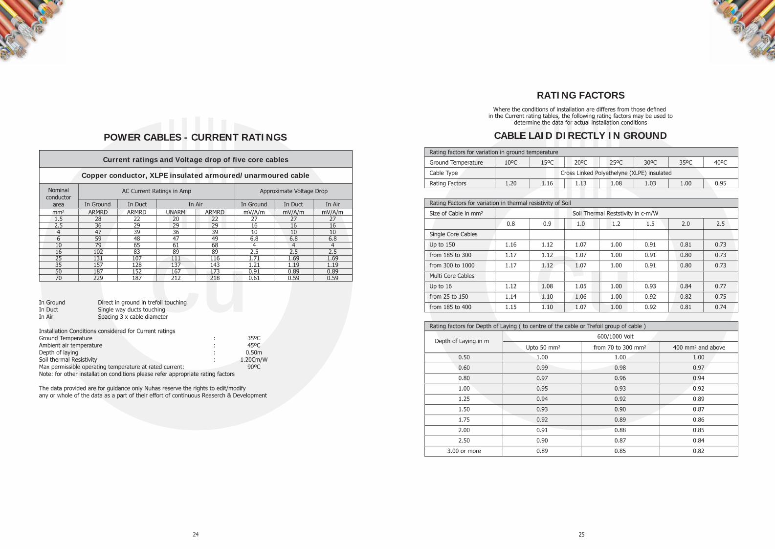
POWER CABLES - CURRENT RATINGS
In Ground In Duct In Air In Ground In Duct In Air mm2 ARMRD ARMRD UNARM ARMRD mV/A/m mV/A/m mV/A/m
AC Current Ratings in Amp Approximate Voltage Drop
In Ground Direct in ground in trefoil touching In Duct - 3 cables flat touching In Air - 3 cables in trefoil touching Installation Conditions considered for Current ratings Ground Temperature : 35ºC Ambient air temperature : 45ºC Depth of laying : 0.50m Soil thermal Resistivity : 1.20Cm/W Max permissible operating temperature at rated current: 90ºC Note: for other installation conditions please refer appropriate rating factors The data provided are for guidance only Nuhas reserve the rights to edit/modify any or whole of the data as a part of their effort of continuous Reaserch & Development
TECHNICAL DATA
22 23
In Ground Direct in ground in trefoil touching In Duct Single way ducts touching In Air Spacing 3 x cable diameter Installation Conditions considered for Current ratings Ground Temperature : 35ºC Ambient air temperature : 45ºC Depth of laying : 0.50m Soil thermal Resistivity : 1.20Cm/W Max. permissible operating temperature at rated current: 90ºC Note: for other installation conditions please refer appropriate rating factors The data provided are for guidance only Nuhas reserve the rights to edit/modify any or whole of the data as a part of their effort of continuous Reaserch & Development
Current ratings and Voltage drop of two core cables
1.5 33 27 23 26 31 31 31 2.5 42 35 32 34 19 19 19 4 56 46 42 46 12 12 12 6 70 58 54 58 7.9 7.9 7.9 10 94 77 71 79 4.7 4.7 4.7 16 121 99 103 105 2.91 2.89 2.89 25 157 127 129 136 1.91 1.89 1.89 35 188 153 160 168 1.31 1.29 1.29 50 223 181 195 203 1.01 0.99 0.99 70 273 224 247 254 0.71 0.69 0.69 95 328 269 305 314 0.51 0.49 0.49 120 372 307 356 363 0.41 0.39 0.39 150 417 345 408 414 0.41 0.39 0.39 185 470 391 472 478 0.31 0.29 0.29 240 544 453 563 564 0.21 0.19 0.19 300 609 509 650 643 0.21 0.19 0.19 400 687 575 756 740 0.20 0.18 0.18
Nominal conductor
area
Copper conductor, XLPE insulated armoured/unarmoured cable
POWER CABLES - CURRENT RATINGS
In Ground In Duct In Air In Ground In Duct In Air mm2 ARMRD ARMRD UNARM ARMRD mV/A/m mV/A/m mV/A/m
AC Current Ratings in Amp Approximate Voltage Drop
In Ground Direct in ground in trefoil touching In Duct Single way ducts touching In Air Spacing 3 x cable diameter Installation Conditions considered for Current ratings Ground Temperature : 35ºC Ambient air temperature : 45ºC Depth of laying : 0.50m Soil thermal Resistivity : 1.20Cm/W Max permissible operating temperature at rated current: 90ºC Note: for other installation conditions please refer appropriate rating factors The data provided are for guidance only Nuhas reserve the rights to edit/modify any or whole of the data as a part of their effort of continuous Reaserch & Development
Current ratings and Voltage drop of three and four core cables
1.5 28 22 20 22 27 27 27 2.5 36 29 29 29 16 16 16 4 47 39 36 39 10 10 10 6 59 48 47 49 6.8 6.8 6.8 10 79 65 61 68 4 4 4 16 102 83 89 89 2.5 2.5 2.5 25 131 107 111 116 1.71 1.69 1.69 35 157 128 137 143 1.21 1.19 1.19 50 187 152 167 173 0.91 0.89 0.89 70 229 187 212 218 0.61 0.59 0.59 95 274 226 262 269 0.51 0.49 0.49 120 312 258 306 312 0.41 0.39 0.39 150 349 291 351 357 0.31 0.29 0.29 185 394 329 406 411 0.31 0.29 0.29 240 455 380 483 485 0.21 0.19 0.19 300 509 427 558 553 0.21 0.19 0.19 400 574 490 647 636 0.21 0.19 0.19
Nominal conductor
area
Copper conductor, XLPE insulated armoured/unarmoured cable
POWER CABLES - CURRENT RATINGS
In Ground In Duct In Air In Ground In Duct In Air mm2 ARMRD ARMRD UNARM ARMRD mV/A/m mV/A/m mV/A/m
AC Current Ratings in Amp Approximate Voltage Drop
24 25
In Ground Direct in ground in trefoil touching In Duct Single way ducts touching In Air Spacing 3 x cable diameter Installation Conditions considered for Current ratings Ground Temperature : 35ºC Ambient air temperature : 45ºC Depth of laying : 0.50m Soil thermal Resistivity : 1.20Cm/W Max permissible operating temperature at rated current: 90ºC Note: for other installation conditions please refer appropriate rating factors The data provided are for guidance only Nuhas reserve the rights to edit/modify any or whole of the data as a part of their effort of continuous Reaserch & Development
Current ratings and Voltage drop of five core cables
1.5 28 22 20 22 27 27 27 2.5 36 29 29 29 16 16 16 4 47 39 36 39 10 10 10 6 59 48 47 49 6.8 6.8 6.8 10 79 65 61 68 4 4 4 16 102 83 89 89 2.5 2.5 2.5 25 131 107 111 116 1.71 1.69 1.69 35 157 128 137 143 1.21 1.19 1.19 50 187 152 167 173 0.91 0.89 0.89 70 229 187 212 218 0.61 0.59 0.59
Nominal conductor
area
Copper conductor, XLPE insulated armoured/unarmoured cable
POWER CABLES - CURRENT RATINGS
In Ground In Duct In Air In Ground In Duct In Air mm2 ARMRD ARMRD UNARM ARMRD mV/A/m mV/A/m mV/A/m
AC Current Ratings in Amp Approximate Voltage Drop
RATING FACTORS
CABLE LAID DIRECTLY IN GROUND
Where the conditions of installation are differes from those defined in the Current rating tables, the following rating factors may be used to
determine the data for actual installation conditions
Rating factors for variation in ground temperature
Ground Temperature 10ºC 15ºC 20ºC 25ºC 30ºC 35ºC 40ºC
Cable Type Cross Linked Polyethelyne (XLPE) insulated
Rating Factors 1.20 1.16 1.13 1.08 1.03 1.00 0.95
Rating Factors for variation in thermal resistivity of Soil
Size of Cable in mm2 Soil Thermal Reststivity in c-m/W
0.8 0.9 1.0 1.2 1.5 2.0 2.5
Single Core Cables
Up to 150 1.16 1.12 1.07 1.00 0.91 0.81 0.73
from 185 to 300 1.17 1.12 1.07 1.00 0.91 0.80 0.73
from 300 to 1000 1.17 1.12 1.07 1.00 0.91 0.80 0.73
Multi Core Cables
Up to 16 1.12 1.08 1.05 1.00 0.93 0.84 0.77
from 25 to 150 1.14 1.10 1.06 1.00 0.92 0.82 0.75
from 185 to 400 1.15 1.10 1.07 1.00 0.92 0.81 0.74
Rating factors for Depth of Laying ( to centre of the cable or Trefoil group of cable )
Depth of Laying in m
600/1000 Volt
0.50 1.00 1.00 1.00
0.60 0.99 0.98 0.97
0.80 0.97 0.96 0.94
1.00 0.95 0.93 0.92
1.25 0.94 0.92 0.89
1.50 0.93 0.90 0.87
1.75 0.92 0.89 0.86
2.00 0.91 0.88 0.85
2.50 0.90 0.87 0.84
3.00 or more 0.89 0.85 0.82
Upto 50 mm2 from 70 to 300 mm2 400 mm2 and above

26 27
Rating Factors for variation in thermal resistivity of Soil
Size of Cable in mm2 Soil Thermal Reststivity in C-m/W
0.8 0.9 1.0 1.2 1.5 2.0 2.5
Single Core Cables
Up to 150 1.10 1.07 1.04 1.00 0.94 0.86 0.80
from 185 to 300 1.11 1.08 1.05 1.00 0.93 0.85 0.79
from 300 to 1000 1.12 1.08 1.05 1.00 0.93 0.84 0.78
Multi Core Cables
Up to 16 1.04 1.03 1.02 1.00 0.97 0.92 0.88
from 25 to 150 1.06 1.04 1.03 1.00 0.95 0.90 0.85
from 185 to 400 1.07 1.05 1.03 1.00 0.95 0.88 0.83
Depth of Laying 600 / 1000 Volts
in m Singlecore Multicore
0.50 1.00 1.00
0.60 0.98 0.99
0.80 0.95 0.98
1.00 0.93 0.96
1.25 0.91 0.95
1.50 0.89 0.94
1.75 0.88 0.94
2.00 0.87 0.93
2.50 0.86 0.92
3.00 0.85 0.91
Rating factors for depth of laying (to centre of duct or trefoil group of ducts)
Rating factors for variation in ground temperature for cables laid in ducts
Air temperature 25ºC 30ºC 35ºC 40ºC 45ºC 50ºC 55ºC
Cable Type Cross Linked Polyethelyne (XLPE) insulated
Rating factor 1.20 1.16 1.11 1.06 1.00 0.94 0.88
CABLE INSTALLED IN AIR
Group Rating factors for single core cables in trefoil single way ducts, horizontal formation (average value)
Spaced by
Number of circuits Touching 0.45 m 0.60 m
2 0.87 0.91 0.93
3 0.78 0.84 0.87
4 0.74 0.81 0.85
5 0.7 0.79 0.83
6 0.69 0.78 0.82
2 0.9 0.93 0.95 0.96
3 0.83 0.88 0.91 0.93
4 0.79 0.85 0.89 0.92
5 0.75 0.83 0.88 0.91
6 0.73 0.82 0.87 0.90
Number of
ducts in ground
Spaced by in m
Touching 0.30 0.45 0.60
Group Rating factors for multicore cables in single way ducts, horizontal formation ( average value)
Rating factors for variation in ground temperature for cables laid in ducts
Ground Temperature 10ºC 15ºC 20ºC 25ºC 30ºC 35ºC 40ºC
Cable Type Cross Linked Polyethelyne (XLPE) insulated
Rating Factors 1.20 1.16 1.13 1.08 1.03 1.00 0.95
CABLES INSTALLED IN DUCTS
up to and including 65 mm 100 130
above 65 & up to and including 90 mm 125 168
Duct Diameter in mm Overall cable diameter
Inside diameter Outside diameter
Recommended Duct dimensions and Cable sizes
Number of circuits Trefoil Laid Flat 0.15 m 0.30 m 0.45 m 0.60 m
2 0.78 0.81 0.83 0.88 0.91 0.93
3 0.66 0.7 0.73 0.79 0.84 0.87
4 0.61 0.64 0.68 0.73 0.81 0.85
5 0.56 0.6 0.64 0.73 0.79 0.85
6 0.53 0.57 0.61 0.71 0.78 0.82
Voltage grade
600/1000 V
Spacing of Circuits
Touching Spaced by
Group Rating Factors for Circuits of three single core cables in trefoil flat touching, in horizontal formation
2 0.81 0.87 0.91 0.93 0.95
3 0.70 0.78 0.84 0.88 0.90
4 0.63 0.74 0.81 0.86 0.89
5 0.59 0.70 0.78 0.84 0.87
6 0.55 0.68 0.77 0.83 0.87
7 0.50 0.66 0.75 0.82 0.86
8 0.48 0.63 0.74 0.81 0.85
Number of Cable group Touching Spaced by
0.15 m 0.30 m 0.45 m 0.60 m
Group Rating Factors for Multicore cables in horizontal formation

28 29
SHORT CIRCUIT CURRENT RATINGS OF 600/1000 V CABLES COPPER CONDUCTOR, XLPE INSULATION
CALCULATION OF SHORT CIRCUIT CURRENT
Nominal cross sectional Short circuit current area of conductor for 1 sec mm2 in KA 1.5 0.21 2.5 0.36 4 0.57 6 0.86 10 1.43 16 2.29 25 3.58 35 5.01 50 7.15 70 10.0 95 13.6 120 17.2 150 21.5 185 26.5 240 34.3 300 42.9 400 57.2 500 71.5 630 90.1 800 114.5 1000 143.1
1000.0 800.0 630.0 500.0 400.0 300.0 240.0 185.0 150.0 120.0 95.0 70.0 50.0
35.0 25.0
16.0
10.0
6.0
4.0
2.5
1.5
1.0 0.75
0.50
0.01
0.10
1.00
10.00
100.00
1000.00
10000.00
0.01 0.1 1 10 Duration of Short Circuit in sec
A k n i t n e r r u C
t i u c r i c t r o h
S
m
m
. q s n i n o i t c e S s s o r
C
f o a e r A
NO/TECH/SCCR/XLPE/MDPB/2010
SHORT CIRCUIT CURRENT CHART OF COPPER CONDUCTOR, XLPE INSULATED 600/1000 V CABLES

30 31

32


1
NUHAS OMAN – QUALITY & RELIABILITY.
INTRODUCTION Nuhas Oman LLC, an integral part of The Al Bahja Group of Companies, is a Quality producer of:
• HV, MV and LV Cables
• Enamelled Copper Wires
• Oxygen Free Continuous Cast Copper Wire Rods
• Drawn Copper Conductors
Our state-of-the-art manufacturing facilities with cutting edge technology ensure that our products meet with
highest quality standards. All our products utilize only OXYGEN FREE HIGH CONDUCTIVITY
ELECTRONIC GRADE Copper produced through the Outokompu UPCAST technology, producing minimum
99.99% pure copper with oxygen content less than 5 ppm. The usage of
Our range of World-class HV, MV and LV Cables includes Single & Multi Core Armoured and Un-armoured
Cables, Specialty, Control, Instrumentation and also LSF, FRLS, LSOH & Custom Cables to meet the
requirements of a broad spectrum of applications ranging from
The Cables are produced in compliance to the requirements of BS, IEC, VDE, ASTM, ICEA & UL
specifications. The by acclaimed independent international certifying agencies
confirming compliance to respective standards.
Nuhas that conform to relevant International standards and
Our quality cycle encompasses raw material and consumable sourcing, in-process production controls and
certification of finished goods prior to delivery. A well-equipped in-house quality assurance facility, manned by
qualified professionals from the industry, ensures that all products delivered meet stringent quality controls
and parameters. Our state-of-the-art laboratory is equipped to test as per relevant international standards as
also to individual customer specifications.
The company endeavours to cater to the domestic, regional and global markets while maintaining the sanctity
of our pristine environment.
is a continuing process at Nuhas Oman LLC and we at Nuhas Oman ceaselessly
strive to achieve product excellence through TOTAL QUALITY MANAGEMENT to provide the best value to
our customers.

2 3
Conductor Size Number of pairs Thickness of Sheath Approx Overall Diameter mm2 mm mm 1 0.8 6.5
0.50 2(Quad) 0.8 7.3 (1/0.8) 5 1.1 11.9 10 1.2 15.3 1 0.8 7.2 0.50 2(Quad) 0.8 8.1 (16/0.2) 5 1.1 13.4
10 1.2 17.5 1 0.8 7.6 1.0 2(Quad) 0.8 8.6
(1/1.13) 5 1.2 14.5 10 1.2 18.7 1 0.8 8.5 1.5 2(Quad) 0.9 9.9
(7/0.53) 5 1.2 16.7 10 1.3 22.0 Note : The above cables can also be manufactured & supplied with LSF on request.
Conductor Size Number of pairs Thickness of Size of Thickness of Approx Overall Bedding Armour wire Sheath Diameter
mm2 mm mm mm mm 1 0.8 0.9 1.3 11.0 0.50 2(Quad) 0.8 0.9 1.3 11.8 (1/0.8) 5 1.1 0.9 1.4 16.5 10 1.2 1.25 1.6 21.1 1 0.8 0.9 1.3 11.7 0.50 2(Quad) 0.8 0.9 1.3 12.6 (16/0.2) 5 1.1 0.9 1.5 18.2 10 1.2 1.25 1.6 23.3 1 0.8 0.9 1.3 12.1 1.0 2(Quad) 0.8 0.9 1.4 13.3 (1/1.13) 5 1.2 1.25 1.5 20.0 10 1.2 1.25 1.7 24.7 1 0.8 0.9 1.4 13.2 1.5 2(Quad) 0.9 0.9 1.4 14.6 (7/0.53) 5 1.2 1.25 1.6 22.4 10 1.3 1.6 1.8 28.8 Note : The above cables can also be manufactured & supplied with LSF on request.
Instrumentation Cable - Unarmoured Type - 1 Cu /PE /Osc /PVC
Reference Standards BS 5308 Part 1
Construction 1) Oxygen Free Electronic Copper Conductor Class 1/ 2 / 5 2) PE Insulation 3) Overall screen with Aluminium Mylar Tape & Tinned Copper drain wire 4) PVC outer sheathing
Applications For instrumentation purpose to reduce crosstalk and to protect signals from outside electromagnetic,electrostatic and radio frequency interference
Technical Data Please refer table A on page No.11
Voltage 300/500 V
TABLE 1 Instrumentation Cables - Armoured Type -2 Cu / PE / Osc / SWA / PVC
Reference Standards BS 5308 part 1
Construction 1) Oxygen Free Electronic Copper Conductor class 1 / 2 & 5 2) PE Insulation 3) Overall screen with Aluminium Mylar tape & Tinned Copper drain wire 4) PVC Bedding 5) Galvanized steel wire Armour 6) PVC Outer sheathing
Applications For instrumentation purpose to reduce crosstalk and to protect signals from outside electromagnetic,electrostatic and radio frequency interference alongwith protection from mechanical damage
Technical Data Please refer Table A on page No.11
Voltage 300/500 V
TABLE 2

4 5
Conductor Size Number of pairs Thickness of Sheath Approx Overall Diameter mm2 mm mm
0.50 2 0.9 10.6
(1/0.8)
5 1.2 13.8 10 1.2 18.6
0.50 2 1.1 12.3
(16/0.2)
5 1.2 15.5 10 1.3 21.5
1.0 2 1.1 13.1
(1/1.13)
5 1.2 15.5 10 1.3 23.0 1.5 2 1.2 15.0 (7/0.53) 5 1.3 19.1 10 1.5 26.9 Note : The above cables can also be manufactured & supplied with LSF on request.
Instrumentation cables - Armoured Type -2 Cu /PE /Isc /Osc /SWA /PVC
Reference Standards BS 5308 Part 1
Construction 1) Oxygen Free Electronic Copper Conductor class 1/2/5 2) PE Insulation 3) Individual pair screen with Aluminium Mylar tape & Tinned Copper drain wire 4) Overall screened with Aluminium Mylar tape & Tinned Copper drain wire 5) PVC Bedding 6) Galvanized steel wire Armour Technical Data Please refer Table A on page No.11 7) PVC Outer sheathing Voltage 300/500 V
Applications For instrumentation purpose to reduce crosstalk and to protect signals from outside electromagnetic,electrostatic and radio frequency interference alongwith protection from mechanical damage
Conductor Size Number of pairs Thickness of Size of Thickness of Approx Overall Bedding Armour wire Sheath Diameter mm2 mm mm mm mm
0.50 2 0.8 0.9 1.3 11.8
(1/0.8)
5 1.1 0.9 1.4 16.5 10 1.2 1.25 1.6 21.1
0.50 2 1.1 0.9 1.5 17.1
(16/0.2)
5 1.2 1.25 1.6 21.3 10 1.3 1.6 1.8 28.3
1.0 2 1.1 0.9 1.5 17.9
(1/1.13)
5 1.2 1.25 1.6 22.3 10 1.3 1.6 1.8 29.8
1.5 2 1.2 1.25 1.6 20.8
(7/0.53)
5 1.3 1.6 1.7 25.8 10 1.5 1.6 1.9 33.9 Note : The above cables can also be manufactured & supplied with LSF on request.
Reference Standards BS 5308 Part 1
Construction 1) Oxygen Free Electronic Copper Conductor Class 2 & 5 2) PE Insulation 3) Individual pair screened with Aluminium Mylar tape & Tinned Copper drain wire 4) Overall screen with Aluminium mylar Tape & Tinned Copper drain wire 5) PVC outer sheathing
Applications
Instrumentation cables Unarmoured Type -1 Cu/PE/ISc/OSc/PVC
For instrumentation purpose to reduce crosstalk and to protect signals from outside electromagnetic,electrostatic and radio frequency interference
Technical Data Please refer Table A on page No.11
Voltage 300/500 V
TABLE 3 TABLE 4

6 7
Reference Standards BS 5308 Part 2
Construction 1) Oxygen Free Electronic Copper Conductor class 2 & 5 2) PVC Insulation 3) Overall screen with Aluminium Myla tape and Tinned Copper drain wire 4) PVC Bedding 5) Galvanized steel wire Armour 6) PVC Outer sheathing
Applications
Instrumentation cables - Armoured Type 2 Cu /PVC /Osc /SWA /PVC
For instrumentation purpose to
reduce crosstalk and to protect
signals from outside
electromagnetic,electrostatic and
radio frequency interference
alongwith protection from
mechanical damage
Conductor Size Number of pairs Thickness of Size of Thickness of Approx Overall Bedding Armour wire Sheath Diameter
mm2 mm mm mm mm 1 0.8 0.9 1.3 11.7 0.50 2 (Quad) 0.8 0.9 1.3 12.6 (16/0.2) 5 1.1 0.9 1.5 18.2 10 1.2 1.25 1.6 23.2 1 0.8 0.9 1.3 12.0 0.75 2 (Quad) 0.8 0.9 1.4 13.2 (24/0.2) 5 1.2 1.25 1.5 20.1 10 1.3 1.6 1.7 25.7 1 0.8 0.9 1.4 13.2 1.5 2 (Quad) 0.9 0.9 1.4 14.6 (7/0.53) 5 1.2 1.25 1.6 22.5 10 1.3 1.6 1.8 28.8 Note : The above cables can also be manufactured & supplied with LSF on request.
Technical Data Please refer Table B on page No.11
Voltage 300/500 V
TABLE 5
TABLE 6
Instrumentation cables Unarmoured Type - 1 Cu /PVC /Osc /PVC
Reference Standards BS 5308 Part 2
Construction 1) Oxygen Free Electronic Copper Conductor Class 2 & 5 2) PVC Insulation 3) Overall screen with Aluminium Mylar Tape & Tinned Copper drain wire 4) PVC outer sheathing
Applications For instrumentation purpose to
reduce crosstalk and to protect
signals from outside
electromagnetic,electrostatic and
radio frequency interference
Technical Data Please refer Table B on page No.11
Voltage 300/500 V
Conductor Size Number of pairs Thickness of Sheath Nominal Overall Diameter
mm2 mm mm 1 0.8 7.2 0.50 2 (Quad) 0.8 8.1 (16/0.2) 5 1.1 13.4 10 1.2 17.5 1 0.8 7.5 0.75 2 (Quad) 0.8 8.5 (24/0.2) 5 1.2 14.6 10 1.3 19.0 1 0.8 8.5 1.5 2 (Quad) 0.9 9.9 (7/0.53) 5 1.2 16.7 10 1.3 22.0 Note : The above cables can also be manufactured & supplied with LSF on request.

8 9
TABLE 7
Instrumentation cables - Unarmoured Type 1 Cu /PVC /Isc /Osc /PVC
Conductor Size Number of pairs Thickness of Sheath Approx Overall Diameter mm² mm mm 0.50 2 1.1 12.3 (16/0.2) 5 1.2 15.5 10 1.3 21.5
0.75 2 1.1 13.1
(24/0.2)
5 1.2 16.6 10 1.3 23.1
1.5 2 1.2 15.0
(7/0.53)
5 1.3 19.1 10 1.5 26.9 Note : The above cables can also be manufactured & supplied with LSF on request.
Reference Standards BS 5308 Part 2
Construction 1) Oxygen Free Electronic Copper Conductor Class 2 & 5 2) PVC Insulation 3) Individual pair screened with Aluminium 4) Overall screened with Aluminium Mylar Tape and Tinned Copper drain wire 5) PVC outer sheathing
Applications For instrumentation purpose to reduce crosstalk and to protect signals from outside electromagnetic,electrostatic and radio frequency interference
Technical Data Please refer Table B on page No.11 Voltage 300/500 V
Conductor Size Number of pairs Thickness of Size of Thickness of Approx Overall Bedding Armour wire Sheath Diameter
mm2 mm mm mm mm
0.50 2 1.1 0.9 1.5 17.1
(16/0.2)
5 1.2 1.25 1.6 21.3 10 1.3 1.6 1.8 28.3
0.75 2 1.1 0.9 1.5 17.9
(24/0.2)
5 1.2 1.25 1.6 22.4 10 1.3 1.6 1.8 29.9
1.5 2 1.2 1.25 1.6 20.8
(7/0.53)
5 1.3 1.6 1.7 25.8 10 1.5 1.6 1.9 33.9 Note : The above cables can also be manufactured & supplied with LSF on request.
TABLE 8
Instrumentation cables - Armoured Type 2 Cu /PVC /Isc /Osc /SWA /PVC
Construction 1) Oxygen Free Electronic Copper Conductor class 2 & 5 2) PVC Insulation 3) Individual pair screen with Aluminium Mylar tape and Tinned Copper drain wire 4) Overall screened with Aluminium Mylar tape and Tinned Copper wire 5) PVC Bedding 6) Galvanized steel wire Armour 7) PVC Outer sheathing
Reference Standards BS 5308 Part 2 Applications For instrumentation purpose to reduce crosstalk and to protect signals from outside electromagnetic,electrostatic and radio frequency interference alongwith protection from mechanical damage
Technical Data Please refer Table B on page No.11 Voltage 300/500 V
Instrumentation cables - Unarmoured Type 1 Cu /PVC /Osc /PVC
Conductor Size Number of cores Thickness of Sheath Approx Overall Diameter
mm2 mm mm
2 0.8 7.2 3 0.8 7.5 0.50 4 0.8 8.1 (16/0.2) 6 0.9 9.5 10 1.1 12.2 20 1.2 15.2 2 0.8 7.5 3 0.8 7.9 0.75 4 0.8 8.5 (24/0.2) 6 0.9 10.1 10 1.1 13.0 20 1.2 16.4 2 0.8 8.5 3 0.9 9.1 1.5 4 0.9 9.9 (7/0.53) 6 1.1 12.0 10 1.2 15.0 20 1.3 19.1 Note : The above cables can also be manufactured & supplied with LSF on request.
Reference Standards BS 5308 Part 2
Construction 1) Oxygen Free Electronic Copper Conductor Class 2 & 5 2) PVC Insulation 3) Overall screen with Aluminium mylar Tape and Tinned Copper drain wire 4) PVC outer sheathing
Applications For instrumentation purpose to reduce crosstalk and to protect signals from outside electromagnetic,electrostatic and radio frequency interference
Technical Data Please refer Table B on page No.11
Voltage 300/500 V
TABLE 9

10 11
Reference Standards BS 5308 Part 2
Construction 1) Oxygen Free Electronic Copper Conductor class 2 & 5 2) PVC Insulation 3) Overall screen with Aluminium Mylar tape and Tinned copper drain wire 4) PVC Bedding 5) Galvanized steel wire Armour 6) PVC Outer sheathing
Applications
Instrumentation cables - Armoured Type 2 Cu /PVC /Osc /SWA /PVC
For instrumentation purpose to
reduce crosstalk and to protect
signals from outside
electromagnetic, electrostatic and
radio frequency interference
alongwith protection from
mechanical damage
Technical Data Please refer Table B on page No.11
Voltage 300/500 V
Conductor Number of Thickness of Size of Thickness of Approx Overall Size Cores Bedding Armour wire Sheath Diameter
mm2 mm mm mm mm 2 0.8 0.9 1.3 11.7 3 0.8 0.9 1.3 12.0 0.50 4 0.8 0.9 1.3 12.6 (16/0.2) 6 0.9 0.90 1.4 14.2 10 1.1 0.9 1.5 17.0 20 1.2 1.25 1.6 19.9 2 0.8 0.9 1.3 12.0 3 0.8 0.9 1.3 12.4 0.75 4 0.8 0.9 1.4 13.2 (24/0.2) 6 0.9 0.90 1.4 14.8 10 1.1 0.9 1.5 17.8 20 1.2 1.3 1.6 21.9 2 0.8 0.90 1.4 13.2 3 0.9 0.90 1.4 13.8 1.5 4 0.9 0.90 1.4 14.6 (7/0.53) 6 1.1 0.9 1.4 16.9 10 1.2 1.25 1.6 20.8 20 1.3 1.6 1.7 25.9 Note : The above cables can also be manufactured & supplied with LSF on request.
TABLE 10
Electrical Properties Unit Cross sectional area of conductor
0.5 mm² 0.75 mm² 1.5 mm² (16/0.2 mm) (24/0.2 mm) (7/0.53 mm) Maximum Mutual Capacitance a) Mutual capacitance of pairs or adjacent cores pF/m 250 250 250 b) Between any core and core screen pF/m 450 450 450 L/R ratio (max) μH/ohm 25 25 40 Max. DC conductor Resistance at 20ºC ohm/km 39.7 26.5 12.3 Minimum Insulation Resistance a) Core to core/screen/armour for 1 km MΩ 25 25 25 b) Screen to screen for 1 km MΩ 1 1 1
TABLE B (PROPERTIES AS PER BS 5308 PART 2)
Conductor nominal area Nom. Insulation thickness Maximum core diameter (mm²) (mm) (mm)
0.5 (16/0.2) 0.60 2.35 0.75 (24/0.2) 0.60 2.45 1.5 (7/0.53) 0.60 3.00
Electrical Properties Unit Cross sectional area of conductor
0.5 mm² 0.5 mm² 1.0 mm² 1.5 mm² (1/0.8 mm) (16/0.2 mm) (1/1.13 mm) (7/0.53 mm) Maximum Mutual Capacitance a) Cables without screens pF/m 75 75 75 85 b) Cables with only collective screens pF/m 75 75 75 85 (except one-pair and two-pair) c) One-pair and two-pair cables collectively pF/m 115 115 115 120 screened and all cables with individual pair screens L/R ratio (max) μH/ohm 25 25 25 40 Max. DC conductor Resistance at 20ºC ohm/km 36.8 39.7 18.4 12.3 Minimum Insulation Resistance a) Core to core/screen/armour for 1 km GΩ 5 5 5 5 b) Screen to screen for 1 km MΩ 1 1 1 1
Instrumentation Cables - Technical data TABLE A
(PROPERTIES AS PER BS 5308 PART 1)
Conductor nominal area Nom. Insulation thickness Maximum core diameter (mm²) (mm) (mm)
0.5 (1/0.8) 0.50 1.90 0.5 (16/0.2) 0.60 2.35 1.0 (1/1.13) 0.60 2.45 1.5 (7/0.53) 0.60 3.00

12 13


INDEX PAGE Description of Cables
Table No. Page No. Company Introduction 1 1 3.6/6(7.2) kV, Single Core Copper conductor XLPE insulated IEC: 60502-2 Aluminium Round Wire Armoured cable 2 2 6/10(12) kV ,Single Core Copper conductor XLPE insulated IEC: 60502-2 Aluminium Round Wire Armoured cable 3 3 8.7/15(17.5) kV ,Single Core Copper conductor XLPE insulated IEC: 60502-2 Aluminium Round Wire Armoured cable 4 4 12/20(24) kV ,Single Core Copper conductor XLPE insulated IEC: 60502-2 Aluminium Round Wire Armoured cable 5 5 18/30(36) kV ,Single Core Copper conductor XLPE insulated IEC: 60502-2 Aluminium Round Wire Armoured cable 6 6 3.6/6(7.2) kV,Single Core Copper conductor XLPE insulated IEC: 60502-2 Un-Armoured cable 7 7 6/10(12) kV,Single Core Copper conductor XLPE insulated IEC: 60502-2 Un-Armoured cable 8 8 8.7/15(17.5) kV,Single Core Copper conductor XLPE insulated IEC: 60502-2 Un-Armoured cable 9 9 12/20(24) kV,Single Core Copper conductor XLPE insulated IEC: 60502-2 Un-Armoured cable 10 10 18/30(36) kV,Single Core Copper conductor XLPE insulated IEC: 60502-2 Un-Armoured cable 11 11 3.6/6(7.2) kV, Three Core Copper conductor XLPE insulated IEC: 60502-2 Steel Round Wire Armoured cable 12 12 6/10(12) kV, Three Core Copper conductor XLPE insulated IEC: 60502-2 Steel Round Wire Armoured cable 13 13 8.7/15(17.5) kV, Three Core Copper conductor XLPE insulated IEC: 60502-2 Steel Round Wire Armoured cable 14 14 12/20(24) kV, Three Core Copper conductor XLPE insulated IEC: 60502-2 Steel Round Wire Armoured cable 15 15 18/30(36) kV, Three Core Copper conductor XLPE insulated IEC: 60502-2 Steel Round Wire Armoured cable 16 16 3.6/6(7.2) kV, Three Core Copper conductor XLPE insulated IEC: 60502-2 Un-Armoured cable 17 17 6/10(12) kV, Three Core Copper conductor XLPE insulated IEC: 60502-2 Un-Armoured cable 18 18 8.7/15(17.5) kV, Three Core Copper conductor XLPE insulated IEC: 60502-2 Un-Armoured cable 19 19 12/20(24) kV, Three Core Copper conductor XLPE insulated IEC: 60502-2 Un-Armoured cable 20 20 18/30(36) kV, Three Core Copper conductor XLPE insulated IEC: 60502-2 Un-Armoured cable 21 21 3.6/6(7.2) kV, Three Core Copper conductor XLPE insulated IEC: 60502-2 Steel Tape Armoured cable 22 22 6/10(12) kV, Three Core Copper conductor XLPE insulated IEC: 60502-2 Steel Tape Armoured cable 23 23 8.7/15(17.5) kV, Three Core Copper conductor XLPE insulated IEC: 60502-2 Steel Tape Armoured cable 24 24 12/20(24) kV, Three Core Copper conductor XLPE insulated IEC: 60502-2 Steel Tape Armoured cable 25 25 18/30(36) kV, Three Core Copper conductor XLPE insulated IEC: 60502-2 Steel Tape Armoured cable 26 26 3.6/6(7.2) kV, Single Core Aluminium conductor XLPE insulated IEC: 60502-2 Aluminium Round Wire Armoured cable 27 27 6/10(12) kV ,Single Core Aluminium conductor XLPE insulated IEC: 60502-2 Aluminium Round Wire Armoured cable 28 28 8.7/15(17.5) kV, Single Core Aluminium conductor XLPE insulated IEC: 60502-2 Aluminium Round Wire Armoured cable 29 29 12/20(24) kV, Single Core Aluminium conductor XLPE insulated IEC: 60502-2 Aluminium Round Wire Armoured cable 30 30 18/30(36) kV, Single Core Aluminium conductor XLPE insulated IEC: 60502-2 Aluminium Round Wire Armoured cable 31 31 3.6/6(7.2) kV, Single Core Aluminium conductor XLPE insulated IEC: 60502-2 Un-Armoured cable 32 32 6/10(12) kV, Single Core Aluminium conductor XLPE insulated IEC: 60502-2 Un-Armoured cable 33 33 8.7/15(17.5) kV, Single Core Aluminium conductor XLPE insulated IEC: 60502-2 Un-Armoured cable 34 34 12/20(24) kV, Single Core Aluminium conductor XLPE insulated IEC: 60502-2 Un-Armoured cable 35 35 18/30(36) kV, Single Core Aluminium conductor XLPE insulated IEC: 60502-2 Un-Armoured cable 36 36 3.6/6(7.2) kV, Three Core Aluminium conductor XLPE insulated IEC: 60502-2 Steel Round Wire Armoured cable 37 37 6/10(12) kV, Three Core Aluminium conductor XLPE insulated IEC: 60502-2 Steel Round Wire Armoured cable 38 38 8.7/15(17.5) kV, Three Core Aluminium conductor XLPE insulated IEC: 60502-2 Steel Round Wire Armoured cable 39 39 12/20(24) kV, Three Core Aluminium conductor XLPE insulated IEC: 60502-2 Steel Round Wire Armoured cable 40 40 18/30(36) kV, Three Core Aluminium conductor XLPE insulated IEC: 60502-2 Steel Round Wire Armoured cable 41 41 3.6/6(7.2) kV, Three Core Aluminium conductor XLPE insulated IEC: 60502-2 Un-Armoured cable 42 42 6/10(12) kV, Three Core Aluminium conductor XLPE insulated IEC: 60502-2 Un-Armoured cable 43 43 8.7/15(17.5) kV, Three Core Aluminium conductor XLPE insulated IEC: 60502-2 Un-Armoured cable 44 44 12/20(24) kV, Three Core Aluminium conductor XLPE insulated IEC: 60502-2 Un-Armoured cable 45 45 18/30(36) kV, Three Core Aluminium conductor XLPE insulated IEC: 60502-2 Un-Armoured cable 46 46 3.6/6(7.2) kV, Three Core Aluminium conductor XLPE insulated IEC: 60502-2 Steel Tape Armoured cable 47 47 6/10(12) kV, Three Core Aluminium conductor XLPE insulated IEC: 60502-2 Steel Tape Armoured cable 48 48 8.7/15(17.5) kV, Three Core Aluminium conductor XLPE insulated IEC: 60502-2 Steel Tape Armoured cable 49 49 12/20(24) kV, Three Core Aluminium conductor XLPE insulated IEC: 60502-2 Steel Tape Armoured cable 50 50 18/30(36) kV, Three Core Aluminium conductor XLPE insulated IEC: 60502-2 Steel Tape Armoured cable 51 51 to 62 Rating factors & general technical information 52 to 54

1 2
Nom
inal
cro
ss s
ectio
nal a
rea
of c
ondu
ctor
m
m2
50
70
95
120
150
185
240
300
400
500
630
800
1000
Co
nduc
tor
diam
eter
(Ap
prox
)
mm
8.
1 9.
7 11
.4
12.9
14
.6
16.0
18
.4
20.6
23
.3
26.3
30
.0
34.1
4 38
.2
Wei
ght
of c
ondu
ctor
(Ap
prox
) kg
/km
40
8 58
6 81
4 10
27
1267
15
78
2074
26
02
3327
42
72
5548
71
00
8900
N
omin
al in
sula
tion
thic
knes
s m
m
2.8
2.8
2.8
2.8
2.8
2.8
2.8
2.8
2.8
2.8
2.8
2.8
2.8
Nom
inal
arm
our
wire
dia
met
er
mm
2.
0 2.
0 2.
0 2.
0 2.
0 2.
0 2.
0 2.
0 2.
0 2.
5 2.
5 2.
5 2.
5 N
omin
al O
uter
she
ath
thic
knes
s m
m
1.8
1.9
1.9
2.0
2.0
2.1
2.2
2.3
2.4
2.5
2.6
2.8
2.9
Ove
rall
Dia
met
er (
Appr
ox)
mm
25
.2
27.1
28
.8
30.6
32
.3
33.9
36
.6
39.2
42
.1
46.5
50
.5
55.2
59
.6
Wei
ght
of c
able
(Ap
prox
) kg
/km
10
79
1335
16
34
1931
22
43
2628
32
47
3900
47
66
6015
75
00
9328
11
384
Stan
dard
pac
king
leng
th (
± 5
%)
m
500
500
500
500
500
500
500
500
500
500
500
400
300
Min
imum
ben
ding
rad
ius
durin
g in
stal
latio
n m
m
378
406
432
459
485
509
549
588
632
697
757
828
894
DC
resi
stan
ce a
t 20
°C (
max
) oh
m/k
m
0.38
7 0.
268
0.19
3 0.
153
0.12
40 0
.099
1 0.
0754
0.
0601
0.
0470
0.
0366
0.
0283
0.
0221
0.
0176
AC
res
ista
nce
at 9
0°C
(app
rox)
oh
m/k
m
0.49
4 0.
342
0.24
6 0.
195
0.15
81 0
.126
0 0.
0961
0.
0766
0.
0599
0.
0466
0.
0360
0.
0281
0.
0224
Re
acta
nce
at 5
0 H
z (a
ppro
x.)
ohm
/km
0.
097
0.09
2 0.
089
0.08
6 0.
084
0.08
2 0.
080
0.07
8 0.
076
0.07
5 0.
074
0.07
3 0.
073
Impe
danc
e at
50
Hz
appr
ox.
ohm
/km
0.
824
0.57
3 0.
418
0.33
4 0.
276
0.22
5 0.
178
0.15
0 0.
125
0.10
8 0.
095
0.08
7 0.
082
Capa
cita
nce
at 5
0 H
z μF
/km
0.
26
0.30
0.
34
0.37
0.
40
0.44
0.
49
0.54
0.
61
0.65
0.
68
0.71
0.
75
Char
ging
cur
rent
/ph
ase
at U
o=3.
6kV,
50H
z (a
ppro
x)
mA/
km
0.30
0.
34
0.38
0.
42
0.45
0.
50
0.55
0.
61
0.69
0.
74
0.77
0.
81
0.85
Co
ntin
uous
Cur
rent
Rat
ing
at c
ond
tem
p. 9
0°C
max
.
1.
Lai
d di
rect
in g
roun
d,
A 18
8 23
0 27
4 30
7 35
0 38
9 44
4 49
5 55
6 60
7 64
9 69
2 73
4 2.
Lai
d in
to d
ucts
A
188
222
260
291
321
350
401
427
453
487
530
564
589
3. L
aid
in a
ir in
tre
foil
touc
hing
A
219
271
328
376
428
481
568
647
734
813
909
997
1075
Sh
ort
circ
uit
curr
ent
ratin
g fo
r 1
sec
Co
nd.t
emp
90°C
initi
al 2
50°C
max
.fina
l
kA
7.15
10
.0
13.6
17
.2
21.5
26
.5
34.3
42
.9
57.2
71
.5
90.1
11
4.5
143.
1
Tech
nica
l Dat
a fo
r 3.
6/6(
7.2)
kV
, Sin
gle
Cor
e C
oppe
r co
nduc
tor
XLP
E in
sula
ted
IEC
: 60
502-
2 A
lum
iniu
m R
ound
Wir
e A
rmou
red
cabl
e Ta
ble
1
Dis
clai
mer
: Th
e co
nten
ts o
f th
is d
ocum
ent
are
pure
ly fo
r in
form
atio
n an
d gu
idan
ce o
nly.
Use
r sh
ould
not
tak
e th
ese
data
as
spec
ifica
tion.
Nuh
as O
man
is in
no
way
res
pons
ible
for
any
loss
or
dam
age,
dire
ct o
r co
nsiq
uent
ial ,
due
to r
elia
nce
of t
he d
ata.
In it
s ef
fort
s fo
r co
ntin
uous
dev
elop
men
t &
impr
ovem
ent
Nuh
as O
man
may
cha
nge
any
or w
hole
of
the
data
with
out
notic
e.
Ass
umpt
ion:
1
Gro
und
tem
pera
ture
35°
C 2.
Air
tem
pera
ture
40°
C
3. T
herm
al r
esis
tivity
of
soil
1.2°
C/m
/W
4. D
epth
of
layi
ng
800
mm
fo
r an
y ot
her
cond
ition
(s)
plea
se r
efer
to
the
appr
opria
te t
able
for
reco
mm
ende
d in
stal
latio
n da
ta.
NUHAS OMAN – QUALITY & RELIABILITY.
INTRODUCTION Nuhas Oman LLC, an integral part of The Al Bahja Group of Companies, is a Quality producer of:
• HV, MV and LV Cables
• Enamelled Copper Wires
• Oxygen Free Continuous Cast Copper Wire Rods
• Drawn Copper Conductors
Our state-of-the-art manufacturing facilities with cutting edge technology ensure that our products meet with
highest quality standards. All our products utilize only OXYGEN FREE HIGH CONDUCTIVITY
ELECTRONIC GRADE Copper produced through the Outokompu UPCAST technology, producing minimum
99.99% pure copper with oxygen content less than 5 ppm. The usage of
Our range of World-class HV, MV and LV Cables includes Single & Multi Core Armoured and Un-armoured
Cables, Specialty, Control, Instrumentation and also LSF, FRLS, LSOH & Custom Cables to meet the
requirements of a broad spectrum of applications ranging from
The Cables are produced in compliance to the requirements of BS, IEC, VDE, ASTM, ICEA & UL
specifications. The by acclaimed independent international certifying agencies
confirming compliance to respective standards.
Nuhas that conform to relevant International standards and
Our quality cycle encompasses raw material and consumable sourcing, in-process production controls and
certification of finished goods prior to delivery. A well-equipped in-house quality assurance facility, manned by
qualified professionals from the industry, ensures that all products delivered meet stringent quality controls
and parameters. Our state-of-the-art laboratory is equipped to test as per relevant international standards as
also to individual customer specifications.
The company endeavours to cater to the domestic, regional and global markets while maintaining the sanctity
of our pristine environment.
is a continuing process at Nuhas Oman LLC and we at Nuhas Oman ceaselessly
strive to achieve product excellence through TOTAL QUALITY MANAGEMENT to provide the best value to
our customers.

3 4
Nom
inal
cro
ss s
ectio
nal a
rea
of c
ondu
ctor
m
m2
50
70
95
120
150
185
240
300
400
500
630
800
1000
Co
nduc
tor
diam
eter
(Ap
prox
) m
m
8.1
9.7
11.4
12
.9
14.6
16
.0
18.4
20
.6
23.3
26
.3
30.0
34
.14
38.2
W
eigh
t of
con
duct
or (
Appr
ox)
g/km
40
8 58
6 81
4 10
27
1267
15
78
2074
26
02
3327
42
72
5548
71
00
8900
N
omin
al in
sula
tion
thic
knes
s m
m
3.4
3.4
3.4
3.4
3.4
3.4
3.4
3.4
3.4
3.4
3.4
3.4
3.4
Nom
inal
arm
our
wire
dia
met
er
mm
2.
0 2.
0 2.
0 2.
0 2.
0 2.
0 2.
0 2.
0 2.
0 2.
5 2.
5 2.
5 2.
5 N
omin
al O
uter
she
ath
thic
knes
s m
m
1.9
1.9
2 2.
0 2.
1 2.
2 2.
2 2.
3 2.
4 2.
6 2.
7 2.
8 3
Ove
rall
Dia
met
er (
Appr
ox)
mm
27
.3
28.9
30
.9
32.5
34
.4
36.0
38
.6
41.0
44
.1
48.5
52
.6
57.0
61
.7
Wei
ght
of c
able
(Ap
prox
) kg
/km
11
91
1440
17
66
2046
23
80
2771
33
90
4041
49
27
6205
77
16
9522
11
620
Stan
dard
pac
king
leng
th (
± 5
%)
m
500
500
500
500
500
500
500
500
500
500
500
400
300
Min
imum
ben
ding
rad
ius
durin
g in
stal
latio
n m
m
409
433
464
487
516
540
578
615
661
728
789
855
925
DC
resi
stan
ce a
t 20
°C (
max
) oh
m/k
m
0.38
7 0.
268
0.19
3 0.
153
0.12
40 0
.099
1 0.
0754
0.
0601
0.
0470
0.
0366
0.
0283
0.
0221
0.
0176
AC
res
ista
nce
at 9
0°C
(app
rox)
oh
m/k
m
0.49
4 0.
342
0.24
6 0.
195
0.15
81 0
.126
0 0.
0961
0.
0766
0.
0599
0.
0466
0.
0360
0.
0281
0.
0224
Re
acta
nce
at 5
0 H
z (a
ppro
x.)
ohm
/km
0.
105
0.10
0 0.
096
0.09
3 0.
090
0.08
8 0.
085
0.08
3 0.
080
0.07
9 0.
077
0.07
5 0.
074
Impe
danc
e at
50
Hz
appr
ox.
ohm
/km
0.
825
0.57
4 0.
420
0.33
6 0.
278
0.22
7 0.
181
0.15
2 0.
128
0.11
0 0.
097
0.08
9 0.
083
Capa
cita
nce
at 5
0 H
z μF
/km
0.
21
0.24
0.
27
0.29
0.
32
0.34
0.
38
0.42
0.
47
0.52
0.
57
0.63
0.
70
Char
ging
cur
rent
/ph
ase
at U
o=6k
V,50
Hz
(app
rox)
m
A/km
0.
40
0.45
0.
50
0.55
0.
60
0.65
0.
72
0.79
0.
89
0.97
1.
08
1.20
1.
32
Cont
inuo
us C
urre
nt R
atin
g at
con
d te
mp.
90°
C m
ax.
1. L
aid
dire
ct in
gro
und,
A
188
230
274
307
350
389
444
495
556
607
649
692
734
2. L
aid
into
duc
ts
A 18
8 22
2 26
0 29
1 32
1 35
0 40
1 42
7 45
3 48
7 53
0 56
4 58
9 3.
Lai
d in
air
in t
refo
il to
uchi
ng
A 21
9 27
1 32
8 37
6 42
8 48
1 56
8 64
7 73
4 81
3 90
9 99
7 10
75
Shor
t ci
rcui
t cu
rren
t ra
ting
for
1 se
c
Cond
.tem
p 90
°C in
itial
250
°C m
ax.fi
nal
kA
7.
15
10.0
13
.6
17.2
21
.5
26.5
34
.3
42.9
57
.2
71.5
90
.1
114.
5 14
3.1
Tech
nica
l Dat
a fo
r 6/
10(1
2) k
V, S
ingl
e C
ore
Cop
per
cond
ucto
r X
LPE
insu
late
d IE
C:
6050
2-2
Alu
min
ium
Rou
nd W
ire
Arm
oure
d ca
ble
Tabl
e 2
Dis
clai
mer
: Th
e co
nten
ts o
f th
is d
ocum
ent
are
pure
ly fo
r in
form
atio
n an
d gu
idan
ce o
nly.
Use
r sh
ould
not
tak
e th
ese
data
as
spec
ifica
tion.
Nuh
as O
man
is in
no
way
res
pons
ible
for
any
loss
or
dam
age,
dire
ct o
r co
nsiq
uent
ial,
due
to r
elia
nce
of t
he d
ata.
In it
s ef
fort
s fo
r co
ntin
uous
dev
elop
men
t &
impr
ovem
ent
Nuh
as O
man
may
cha
nge
any
or w
hole
of
the
data
with
out
notic
e.
Assu
mpt
ion:
1
Gro
und
tem
pera
ture
35°
C 2.
Air
tem
pera
ture
40°
C
3. T
herm
al r
esis
tivity
of
soil
1.2°
C/m
/W
4.
Dep
th o
f la
ying
80
0 m
m
for
any
othe
r co
nditi
on(s
) pl
ease
ref
er t
o th
e ap
prop
riate
tab
le fo
r re
com
men
ded
inst
alla
tion
data
.
Tech
nica
l Dat
a fo
r 8.
7/15
(17.
5) k
V, S
ingl
e C
ore
Cop
per
cond
ucto
r X
LPE
insu
late
d IE
C:
6050
2-2
Alu
min
ium
Rou
nd W
ire
Arm
oure
d ca
ble
Tabl
e 3
Dis
clai
mer
: Th
e co
nten
ts o
f th
is d
ocum
ent
are
pure
ly fo
r in
form
atio
n an
d gu
idan
ce o
nly.
Use
r sh
ould
not
tak
e th
ese
data
as
spec
ifica
tion.
Nuh
as O
man
is in
no
way
res
pons
ible
for
any
loss
or
dam
age,
dire
ct o
r co
nsiq
uent
ial,
due
to r
elia
nce
of t
he d
ata.
In it
s ef
fort
s fo
r co
ntin
uous
dev
elop
men
t &
impr
ovem
ent
Nuh
as O
man
may
cha
nge
any
or w
hole
of
the
data
with
out
notic
e
Ass
umpt
ion:
1
Gro
und
tem
pera
ture
35°
C 2.
Air
tem
pera
ture
40°
C
3. T
herm
al r
esis
tivity
of
soil
1.2°
C/m
/W
4. D
epth
of
layi
ng
800
mm
fo
r an
y ot
her
cond
ition
(s)
plea
se r
efer
to
the
appr
opria
te t
able
for
reco
mm
ende
d in
stal
latio
n da
ta.
Nom
inal
cro
ss s
ectio
nal a
rea
of c
ondu
ctor
m
m2
50
70
95
120
150
185
240
300
400
500
630
800
1000
Co
nduc
tor
diam
eter
(Ap
prox
)
mm
8.
1 9.
7 11
.4
12.9
14
.6
16.0
18
.4
20.6
23
.3
26.3
30
.0
34.1
4 38
.2
Wei
ght
of c
ondu
ctor
(Ap
prox
) kg
/km
40
8 58
6 81
4 10
27
1267
15
78
2074
26
02
3327
42
72
5548
71
00
8900
N
omin
al in
sula
tion
thic
knes
s m
m
4.5
4.5
4.5
4.5
4.5
4.5
4.5
4.5
4.5
4.5
4.5
4.5
4.5
Nom
inal
arm
our
wire
dia
met
er
mm
2.
0 2.
0 2.
0 2.
0 2.
0 2.
0 2.
0 2.
0 2.
5 2.
5 2.
5 2.
5 2.
5 N
omin
al O
uter
she
ath
thic
knes
s m
m
1.9
2 2.
1 2.
1 2.
2 2.
2 2.
3 2.
4 2.
5 2.
6 2.
8 2.
9 3.
1 O
vera
ll D
iam
eter
(Ap
prox
) m
m
29.5
31
.4
33.4
34
.9
36.9
38
.3
41.0
43
.4
47.5
50
.8
55.0
59
.6
64.1
W
eigh
t of
cab
le (
Appr
ox)
kg/k
m
1321
15
99
1925
22
12
2563
29
43
3582
42
44
5280
64
19
7972
98
10
1191
4 St
anda
rd p
acki
ng le
ngth
(±
5%
) m
50
0 50
0 50
0 50
0 50
0 50
0 50
0 50
0 50
0 50
0 50
0 40
0 30
0 M
inim
um b
endi
ng r
adiu
s du
ring
inst
alla
tion
mm
44
2 47
1 50
0 52
3 55
4 57
5 61
5 65
2 71
3 76
1 82
6 89
3 96
2 D
C re
sist
ance
at
20°C
(m
ax)
ohm
/km
0.
387
0.26
8 0.
193
0.15
3 0.
1240
0.0
991
0.07
54
0.06
01
0.04
70
0.03
66
0.02
83
0.02
21
0.01
76
AC r
esis
tanc
e at
90°
C (a
ppro
x)
ohm
/km
0.
494
0.34
2 0.
246
0.19
5 0.
1581
0.1
260
0.09
61
0.07
66
0.05
99
0.04
66
0.03
60
0.02
81
0.02
24
Reac
tanc
e at
50
Hz
(app
rox.
) oh
m/k
m
0.11
3 0.
107
0.10
2 0.
099
0.09
6 0.
093
0.09
0 0.
087
0.08
4 0.
082
0.08
0 0.
078
0.07
7 Im
peda
nce
at 5
0 H
z ap
prox
. oh
m/k
m
0.82
6 0.
576
0.42
1 0.
338
0.28
0 0.
229
0.18
3 0.
155
0.13
0 0.
113
0.10
0 0.
091
0.08
5 Ca
paci
tanc
e at
50
Hz
μF/k
m
0.18
0.
20
0.22
0.
24
0.26
0.
28
0.31
0.
34
0.38
0.
42
0.46
0.
51
0.56
Ch
argi
ng c
urre
nt /
phas
e at
Uo=
8.7k
V,50
Hz
(app
rox)
m
A/km
0.
49
0.54
0.
60
0.65
0.
71
0.77
0.
85
0.92
1.
04
1.14
1.
25
1.39
1.
53
Cont
inuo
us C
urre
nt R
atin
g at
con
d te
mp.
90°
C m
ax.
1. L
aid
dire
ct in
gro
und,
A
188
230
274
307
350
389
444
495
556
607
649
692
734
2. L
aid
into
duc
ts
A 18
8 22
2 26
0 29
1 32
1 35
0 40
1 42
7 45
3 48
7 53
0 56
4 58
9 3.
Lai
d in
air
in t
refo
il to
uchi
ng
A 21
9 27
1 32
8 37
6 42
8 48
1 56
8 64
7 73
4 81
3 90
9 99
7 10
75
Shor
t ci
rcui
t cu
rren
t ra
ting
for
1 se
c
Cond
.tem
p 90
°C in
itial
250
°C m
ax.fi
nal
kA
7.
15
10.0
13
.6
17.2
21
.5
26.5
34
.3
42.9
57
.2
71.5
90
.1
114.
5 14
3.1
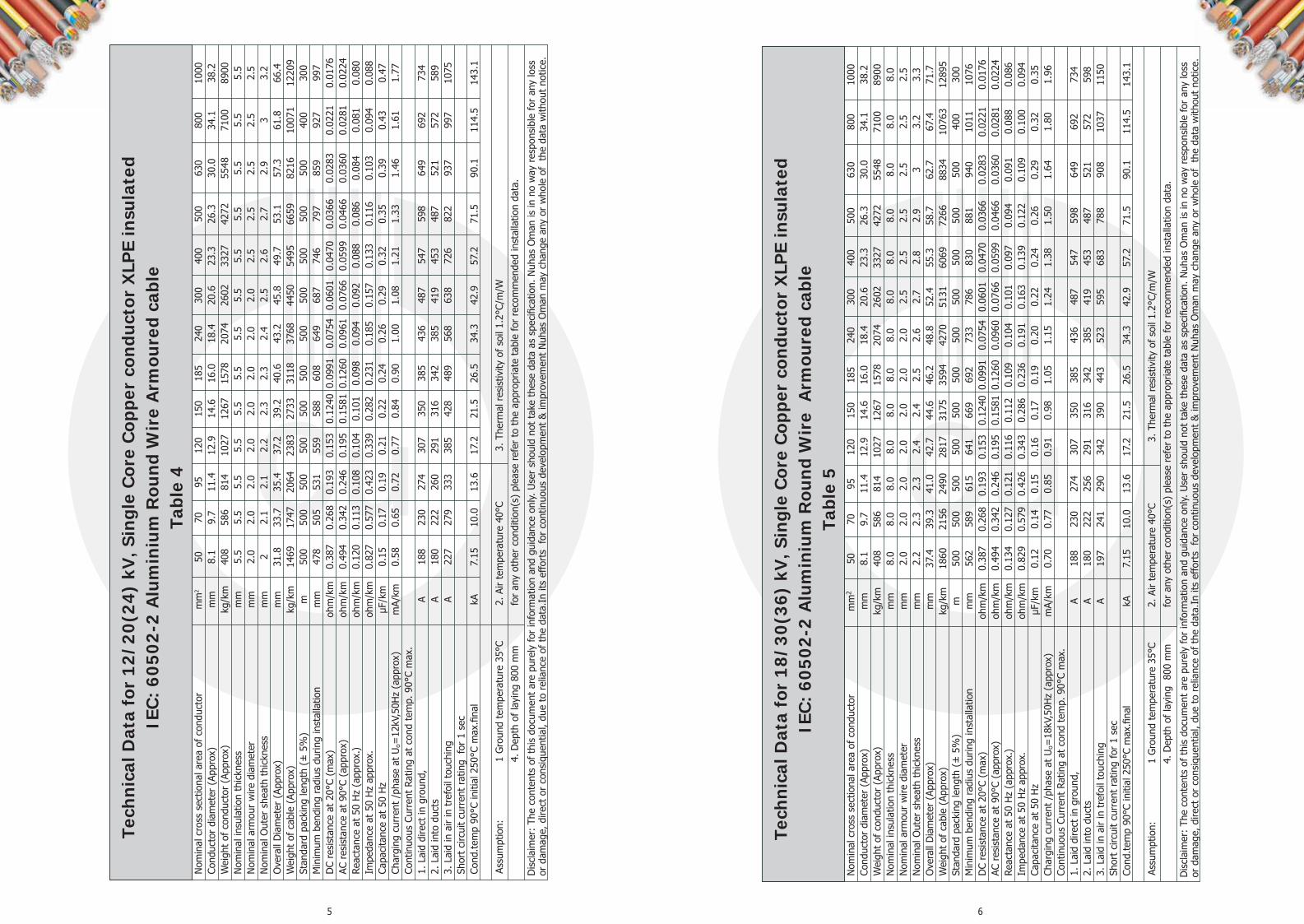
5 6
Tech
nica
l Dat
a fo
r 12
/20(
24)
kV, S
ingl
e C
ore
Cop
per
cond
ucto
r X
LPE
insu
late
d IE
C:
6050
2-2
Alu
min
ium
Rou
nd W
ire
Arm
oure
d ca
ble
Tabl
e 4
Nom
inal
cro
ss s
ectio
nal a
rea
of c
ondu
ctor
m
m2
50
70
95
120
150
185
240
300
400
500
630
800
1000
Co
nduc
tor
diam
eter
(Ap
prox
)
mm
8.
1 9.
7 11
.4
12.9
14
.6
16.0
18
.4
20.6
23
.3
26.3
30
.0
34.1
38
.2
Wei
ght
of c
ondu
ctor
(Ap
prox
) kg
/km
40
8 58
6 81
4 10
27
1267
15
78
2074
26
02
3327
42
72
5548
71
00
8900
N
omin
al in
sula
tion
thic
knes
s m
m
5.5
5.5
5.5
5.5
5.5
5.5
5.5
5.5
5.5
5.5
5.5
5.5
5.5
Nom
inal
arm
our
wire
dia
met
er
mm
2.
0 2.
0 2.
0 2.
0 2.
0 2.
0 2.
0 2.
0 2.
5 2.
5 2.
5 2.
5 2.
5 N
omin
al O
uter
she
ath
thic
knes
s m
m
2 2.
1 2.
1 2.
2 2.
3 2.
3 2.
4 2.
5 2.
6 2.
7 2.
9 3
3.2
Ove
rall
Dia
met
er (
Appr
ox)
mm
31
.8
33.7
35
.4
37.2
39
.2
40.6
43
.2
45.8
49
.7
53.1
57
.3
61.8
66
.4
Wei
ght
of c
able
(Ap
prox
) kg
/km
14
69
1747
20
64
2383
27
33
3118
37
68
4450
54
95
6659
82
16
1007
1 12
209
Stan
dard
pac
king
leng
th (
± 5
%)
m
500
500
500
500
500
500
500
500
500
500
500
400
300
Min
imum
ben
ding
rad
ius
durin
g in
stal
latio
n m
m
478
505
531
559
588
608
649
687
746
797
859
927
997
DC
resi
stan
ce a
t 20
°C (
max
) oh
m/k
m
0.38
7 0.
268
0.19
3 0.
153
0.12
40 0
.099
1 0.
0754
0.
0601
0.
0470
0.
0366
0.
0283
0.
0221
0.
0176
AC
res
ista
nce
at 9
0°C
(app
rox)
oh
m/k
m
0.49
4 0.
342
0.24
6 0.
195
0.15
81 0
.126
0 0.
0961
0.
0766
0.
0599
0.
0466
0.
0360
0.
0281
0.
0224
Re
acta
nce
at 5
0 H
z (a
ppro
x.)
ohm
/km
0.
120
0.11
3 0.
108
0.10
4 0.
101
0.09
8 0.
094
0.09
2 0.
088
0.08
6 0.
084
0.08
1 0.
080
Impe
danc
e at
50
Hz
appr
ox.
ohm
/km
0.
827
0.57
7 0.
423
0.33
9 0.
282
0.23
1 0.
185
0.15
7 0.
133
0.11
6 0.
103
0.09
4 0.
088
Capa
cita
nce
at 5
0 H
z μF
/km
0.
15
0.17
0.
19
0.21
0.
22
0.24
0.
26
0.29
0.
32
0.35
0.
39
0.43
0.
47
Char
ging
cur
rent
/ph
ase
at U
o=12
kV,5
0Hz
(app
rox)
m
A/km
0.
58
0.65
0.
72
0.77
0.
84
0.90
1.
00
1.08
1.
21
1.33
1.
46
1.61
1.
77
Cont
inuo
us C
urre
nt R
atin
g at
con
d te
mp.
90°
C m
ax.
1. L
aid
dire
ct in
gro
und,
A
188
230
274
307
350
385
436
487
547
598
649
692
734
2. L
aid
into
duc
ts
A 18
0 22
2 26
0 29
1 31
6 34
2 38
5 41
9 45
3 48
7 52
1 57
2 58
9 3.
Lai
d in
air
in t
refo
il to
uchi
ng
A 22
7 27
9 33
3 38
5 42
8 48
9 56
8 63
8 72
6 82
2 93
7 99
7 10
75
Shor
t ci
rcui
t cu
rren
t ra
ting
for
1 se
c
Cond
.tem
p 90
°C in
itial
250
°C m
ax.fi
nal
kA
7.
15
10.0
13
.6
17.2
21
.5
26.5
34
.3
42.9
57
.2
71.5
90
.1
114.
5 14
3.1
Assu
mpt
ion:
1
Gro
und
tem
pera
ture
35°
C 2.
Air
tem
pera
ture
40°
C
3. T
herm
al r
esis
tivity
of
soil
1.2°
C/m
/W
4.
Dep
th o
f la
ying
800
mm
fo
r an
y ot
her
cond
ition
(s)
plea
se r
efer
to
the
appr
opria
te t
able
for
reco
mm
ende
d in
stal
latio
n da
ta.
Dis
clai
mer
: Th
e co
nten
ts o
f th
is d
ocum
ent
are
pure
ly fo
r in
form
atio
n an
d gu
idan
ce o
nly.
Use
r sh
ould
not
tak
e th
ese
data
as
spec
ifica
tion.
Nuh
as O
man
is in
no
way
res
pons
ible
for
any
loss
or
dam
age,
dire
ct o
r co
nsiq
uent
ial,
due
to r
elia
nce
of t
he d
ata.
In it
s ef
fort
s fo
r co
ntin
uous
dev
elop
men
t &
impr
ovem
ent
Nuh
as O
man
may
cha
nge
any
or w
hole
of
the
dat
a w
ithou
t no
tice.
Tech
nica
l Dat
a fo
r 18
/30(
36)
kV, S
ingl
e C
ore
Cop
per
cond
ucto
r X
LPE
insu
late
d IE
C:
6050
2-2
Alu
min
ium
Rou
nd W
ire
Arm
oure
d ca
ble
Tabl
e 5
Dis
clai
mer
: Th
e co
nten
ts o
f th
is d
ocum
ent
are
pure
ly fo
r in
form
atio
n an
d gu
idan
ce o
nly.
Use
r sh
ould
not
tak
e th
ese
data
as
spec
ifica
tion.
Nuh
as O
man
is in
no
way
res
pons
ible
for
any
loss
or
dam
age,
dire
ct o
r co
nsiq
uent
ial,
due
to r
elia
nce
of t
he d
ata.
In it
s ef
fort
s fo
r co
ntin
uous
dev
elop
men
t &
impr
ovem
ent
Nuh
as O
man
may
cha
nge
any
or w
hole
of
the
dat
a w
ithou
t no
tice.
Assu
mpt
ion:
1
Gro
und
tem
pera
ture
35°
C 2.
Air
tem
pera
ture
40°
C
3.
The
rmal
res
istiv
ity o
f so
il 1.
2°C/
m/W
4. D
epth
of
layi
ng
800
mm
fo
r an
y ot
her
cond
ition
(s)
plea
se r
efer
to
the
appr
opria
te t
able
for
reco
mm
ende
d in
stal
latio
n da
ta.
Nom
inal
cro
ss s
ectio
nal a
rea
of c
ondu
ctor
m
m2
50
70
95
120
150
185
240
300
400
500
630
800
1000
Co
nduc
tor
diam
eter
(Ap
prox
)
mm
8.
1 9.
7 11
.4
12.9
14
.6
16.0
18
.4
20.6
23
.3
26.3
30
.0
34.1
38
.2
Wei
ght
of c
ondu
ctor
(Ap
prox
) kg
/km
40
8 58
6 81
4 10
27
1267
15
78
2074
26
02
3327
42
72
5548
71
00
8900
N
omin
al in
sula
tion
thic
knes
s m
m
8.0
8.0
8.0
8.0
8.0
8.0
8.0
8.0
8.0
8.0
8.0
8.0
8.0
Nom
inal
arm
our
wire
dia
met
er
mm
2.
0 2.
0 2.
0 2.
0 2.
0 2.
0 2.
0 2.
5 2.
5 2.
5 2.
5 2.
5 2.
5 N
omin
al O
uter
she
ath
thic
knes
s m
m
2.2
2.3
2.3
2.4
2.4
2.5
2.6
2.7
2.8
2.9
3 3.
2 3.
3 O
vera
ll D
iam
eter
(Ap
prox
) m
m
37.4
39
.3
41.0
42
.7
44.6
46
.2
48.8
52
.4
55.3
58
.7
62.7
67
.4
71.7
W
eigh
t of
cab
le (
Appr
ox)
kg/k
m
1860
21
56
2490
28
17
3175
35
94
4270
51
31
6069
72
66
8834
10
763
1289
5 St
anda
rd p
acki
ng le
ngth
(±
5%
) m
50
0 50
0 50
0 50
0 50
0 50
0 50
0 50
0 50
0 50
0 50
0 40
0 30
0 M
inim
um b
endi
ng r
adiu
s du
ring
inst
alla
tion
mm
56
2 58
9 61
5 64
1 66
9 69
2 73
3 78
6 83
0 88
1 94
0 10
11
1076
D
C re
sist
ance
at
20°C
(m
ax)
ohm
/km
0.
387
0.26
8 0.
193
0.15
3 0.
1240
0.0
991
0.07
54
0.06
01
0.04
70
0.03
66
0.02
83
0.02
21
0.01
76
AC r
esis
tanc
e at
90°
C (a
ppro
x)
ohm
/km
0.
494
0.34
2 0.
246
0.19
5 0.
1581
0.1
260
0.09
60
0.07
66
0.05
99
0.04
66
0.03
60
0.02
81
0.02
24
Reac
tanc
e at
50
Hz
(app
rox.
) oh
m/k
m
0.13
4 0.
127
0.12
1 0.
116
0.11
2 0.
109
0.10
4 0.
101
0.09
7 0.
094
0.09
1 0.
088
0.08
6 Im
peda
nce
at 5
0 H
z ap
prox
. oh
m/k
m
0.82
9 0.
579
0.42
6 0.
343
0.28
6 0.
236
0.19
1 0.
163
0.13
9 0.
122
0.10
9 0.
100
0.09
4 Ca
paci
tanc
e at
50
Hz
μF/k
m
0.12
0.
14
0.15
0.
16
0.17
0.
19
0.20
0.
22
0.24
0.
26
0.29
0.
32
0.35
Ch
argi
ng c
urre
nt /
phas
e at
Uo=
18kV
,50H
z (a
ppro
x)
mA/
km
0.70
0.
77
0.85
0.
91
0.98
1.
05
1.15
1.
24
1.38
1.
50
1.64
1.
80
1.96
Co
ntin
uous
Cur
rent
Rat
ing
at c
ond
tem
p. 9
0°C
max
.
1.
Lai
d di
rect
in g
roun
d,
A 18
8 23
0 27
4 30
7 35
0 38
5 43
6 48
7 54
7 59
8 64
9 69
2 73
4 2.
Lai
d in
to d
ucts
A
180
222
256
291
316
342
385
419
453
487
521
572
598
3. L
aid
in a
ir in
tre
foil
touc
hing
A
197
241
290
342
390
443
523
595
683
788
908
1037
11
50
Shor
t ci
rcui
t cu
rren
t ra
ting
for
1 se
c
Cond
.tem
p 90
°C in
itial
250
°C m
ax.fi
nal
kA
7.
15
10.0
13
.6
17.2
21
.5
26.5
34
.3
42.9
57
.2
71.5
90
.1
114.
5 14
3.1

7 8
Tech
nica
l Dat
a fo
r 3.
6/6(
7.2)
kV
, Sin
gle
Cor
e C
oppe
r co
nduc
tor
XLP
E in
sula
ted
IEC
: 60
502-
2 U
n-A
rmou
red
cabl
e Ta
ble
6 N
omin
al c
ross
sec
tiona
l are
a of
con
duct
or
mm
2 50
70
95
12
0 15
0 18
5 24
0 30
0 40
0 50
0 63
0 80
0 10
00
Cond
ucto
r di
amet
er (
Appr
ox)
m
m
8.1
9.7
11.4
12
.9
14.6
16
.0
18.4
20
.6
23.3
26
.3
30.0
34
.14
38.2
W
eigh
t of
con
duct
or (
Appr
ox)
kg/k
m
408
586
814
1027
12
67
1578
20
74
2602
33
27
4272
55
48
7100
89
00
Nom
inal
insu
latio
n th
ickn
ess
mm
2.
8 2.
8 2.
8 2.
8 2.
8 2.
8 2.
8 2.
8 2.
8 2.
8 2.
8 2.
8 2.
8 N
omin
al O
uter
she
ath
thic
knes
s m
m
1.7
1.7
1.8
1.8
1.9
2.0
2.0
2.1
2.2
2.3
2.5
2.6
2.8
Ove
rall
Dia
met
er (
Appr
ox)
mm
21
.0
22.7
24
.6
26.2
28
.1
29.7
32
.2
34.8
37
.7
41.1
45
.3
49.8
54
.4
Wei
ght
of c
able
(Ap
prox
) kg
/km
79
8 10
19
1304
15
64
1864
22
28
2795
34
12
4236
53
03
6740
84
64
1046
8 St
anda
rd p
acki
ng le
ngth
(±
5%
) m
50
0 50
0 50
0 50
0 50
0 50
0 50
0 50
0 50
0 50
0 50
0 40
0 30
0 M
inim
um b
endi
ng r
adiu
s du
ring
inst
alla
tion
mm
42
0 45
3 49
2 52
4 56
3 59
5 64
4 69
5 75
4 82
2 90
5 99
6 10
88
DC
resi
stan
ce a
t 20
°C (
max
) oh
m/k
m
0.38
7 0.
268
0.19
3 0.
153
0.12
40 0
.099
1 0.
0754
0.
0601
0.
0470
0.
0366
0.
0283
0.
0221
0.
0176
AC
res
ista
nce
at 9
0°C
(app
rox)
oh
m/k
m
0.49
4 0.
342
0.24
6 0.
195
0.15
81 0
.126
0 0.
0961
0.
0766
0.
0599
0.
0466
0.
0360
0.
0281
0.
0224
Re
acta
nce
at 5
0 H
z (a
ppro
x.)
ohm
/km
0.
097
0.09
2 0.
089
0.08
6 0.
084
0.08
2 0.
080
0.07
8 0.
076
0.07
5 0.
074
0.07
3 0.
073
Impe
danc
e at
50
Hz
appr
ox.
ohm
/km
0.
824
0.57
3 0.
418
0.33
4 0.
276
0.22
5 0.
178
0.15
0 0.
125
0.10
8 0.
095
0.08
7 0.
082
Capa
cita
nce
at 5
0 H
z μF
/km
0.
26
0.30
0.
34
0.37
0.
40
0.44
0.
49
0.54
0.
61
0.65
0.
68
0.71
0.
75
Char
ging
cur
rent
/ph
ase
at U
o=3.
6kV,
50H
z (a
ppro
x)
mA/
km
0.30
0.
34
0.38
0.
42
0.45
0.
50
0.55
0.
61
0.69
0.
74
0.77
0.
81
0.85
Co
ntin
uous
Cur
rent
Rat
ing
at c
ond
tem
p. 9
0°C
max
. 1.
Lai
d di
rect
in g
roun
d,
A 18
8 23
0 27
4 30
7 35
0 39
3 45
3 51
3 58
1 64
1 70
9 78
6 85
4 2.
Lai
d in
to d
ucts
A
192
230
274
307
342
376
431
478
521
581
641
709
778
3. L
aid
in a
ir in
tre
foil
touc
hing
A
206
249
314
363
410
472
560
647
734
822
970
1110
12
24
Shor
t ci
rcui
t cu
rren
t ra
ting
for
1 se
c Co
nd.t
emp
90°C
initi
al 2
50°C
max
.fina
l
kA
7.15
10
.0
13.6
17
.2
21.5
26
.5
34.3
42
.9
57.2
71
.5
90.1
11
4.5
143.
1
Assu
mpt
ion:
1
Gro
und
tem
pera
ture
35°
C 2.
Air
tem
pera
ture
40°
C 3.
The
rmal
res
istiv
ity o
f so
il 1.
2°C/
m/W
4. D
epth
of
layi
ng
800
mm
fo
r an
y ot
her
cond
ition
(s)
plea
se r
efer
to
the
appr
opria
te t
able
for
reco
mm
ende
d in
stal
latio
n da
ta.
Dis
clai
mer
: Th
e co
nten
ts o
f th
is d
ocum
ent
are
pure
ly fo
r in
form
atio
n an
d gu
idan
ce o
nly.
Use
r sh
ould
not
tak
e th
ese
data
as
spec
ifica
tion.
Nuh
as O
man
is in
no
way
res
pons
ible
for
any
loss
or
dam
age,
dire
ct o
r co
nsiq
uent
ial ,
due
to r
elia
nce
of t
he d
ata.
In it
s ef
fort
s fo
r co
ntin
uous
dev
elop
men
t &
impr
ovem
ent
Nuh
as O
man
may
cha
nge
any
or w
hole
of
the
data
with
out
notic
e.
Tech
nica
l Dat
a fo
r 6/
10(1
2) k
V, S
ingl
e C
ore
Cop
per
cond
ucto
r X
LPE
insu
late
d IE
C:
6050
2-2
Un-
Arm
oure
d c
able
Ta
ble
7
Dis
clai
mer
: Th
e co
nten
ts o
f th
is d
ocum
ent
are
pure
ly fo
r in
form
atio
n an
d gu
idan
ce o
nly.
Use
r sh
ould
not
tak
e th
ese
data
as
spec
ifica
tion.
Nuh
as O
man
is in
no
way
res
pons
ible
for
any
loss
or
dam
age,
dire
ct o
r co
nsiq
uent
ial,
due
to r
elia
nce
of t
he d
ata.
In it
s ef
fort
s fo
r co
ntin
uous
dev
elop
men
t &
impr
ovem
ent
Nuh
as O
man
may
cha
nge
any
or w
hole
of
the
data
with
out
notic
e.
Assu
mpt
ion:
1
Gro
und
tem
pera
ture
35°
C 2.
Air
tem
pera
ture
40°
3.
The
rmal
res
istiv
ity o
f so
il 1.
2°C/
m/W
4. D
epth
of
layi
ng
800
mm
fo
r an
y ot
her
cond
ition
(s)
plea
se r
efer
to
the
appr
opria
te t
able
for
reco
mm
ende
d in
stal
latio
n da
ta.
Nom
inal
cro
ss s
ectio
nal a
rea
of c
ondu
ctor
m
m2
50
70
95
120
150
185
240
300
400
500
630
800
1000
Co
nduc
tor
diam
eter
(Ap
prox
)
mm
8.
1 9.
7 11
.4
12.9
14
.6
16.0
18
.4
20.6
23
.3
26.3
30
.0
34.1
4 38
.2
Wei
ght
of c
ondu
ctor
(Ap
prox
) kg
/km
40
8 58
6 81
4 10
27
1267
15
78
2074
26
02
3327
42
72
5548
71
00
8900
N
omin
al in
sula
tion
thic
knes
s m
m
3.4
3.4
3.4
3.4
3.4
3.4
3.4
3.4
3.4
3.4
3.4
3.4
3.4
Nom
inal
Out
er s
heat
h th
ickn
ess
mm
1.
7 1.
8 1.
9 1.
9 2.
0 2
2.1
2.2
2.3
2.4
2.5
2.7
2.8
Ove
rall
Dia
met
er (
Appr
ox)
mm
22
.9
24.7
26
.7
28.3
30
.2
31.6
34
.4
36.8
39
.9
43.1
47
.2
51.8
56
.3
Wei
ght
of c
able
(Ap
prox
) kg
/km
87
1 11
08
1406
16
66
1973
23
28
2926
35
44
4388
54
57
6897
86
49
1064
3 St
anda
rd p
acki
ng le
ngth
(±
5%
) m
50
0 50
0 50
0 50
0 50
0 50
0 50
0 50
0 50
0 50
0 50
0 40
0 30
0 M
inim
um b
endi
ng r
adiu
s du
ring
inst
alla
tion
mm
45
7 49
4 53
4 56
5 60
4 63
1 68
7 73
6 79
7 86
2 94
4 10
36
1125
D
C re
sist
ance
at
20°C
(m
ax)
ohm
/km
0.
387
0.26
8 0.
193
0.15
3 0.
1240
0.0
991
0.07
54
0.06
01
0.04
70
0.03
66
0.02
83
0.02
21
0.01
76
AC r
esis
tanc
e at
90°
C (a
ppro
x)
ohm
/km
0.
494
0.34
2 0.
246
0.19
5 0.
1581
0.1
260
0.09
61
0.07
66
0.05
99
0.04
66
0.03
60
0.02
81
0.02
24
Reac
tanc
e at
50
Hz
(app
rox.
) oh
m/k
m
0.10
5 0.
100
0.09
6 0.
093
0.09
0 0.
088
0.08
5 0.
083
0.08
0 0.
079
0.07
7 0.
075
0.07
4 Im
peda
nce
at 5
0 H
z ap
prox
. oh
m/k
m
0.82
5 0.
574
0.42
0 0.
336
0.27
8 0.
227
0.18
1 0.
152
0.12
8 0.
110
0.09
7 0.
089
0.08
3 Ca
paci
tanc
e at
50
Hz
μF/k
m
0.21
0.
24
0.27
0.
29
0.32
0.
34
0.38
0.
42
0.47
0.
52
0.57
0.
63
0.70
Ch
argi
ng c
urre
nt /
phas
e at
Uo=
6kV,
50H
z (a
ppro
x)
mA/
km
0.40
0.
45
0.50
0.
55
0.60
0.
65
0.72
0.
79
0.89
0.
97
1.08
1.
20
1.32
Co
ntin
uous
Cur
rent
Rat
ing
at c
ond
tem
p. 9
0°C
max
. 1.
Lai
d di
rect
in g
roun
d,
A 18
8 23
0 27
4 30
7 35
0 39
3 45
3 51
3 58
1 64
1 70
9 78
6 85
4 2.
Lai
d in
to d
ucts
A
192
230
274
307
342
376
431
478
521
581
641
709
778
3. L
aid
in a
ir in
tre
foil
touc
hing
A
206
249
314
363
410
472
560
647
734
822
970
1110
12
24
Shor
t ci
rcui
t cu
rren
t ra
ting
for
1 se
c Co
nd.t
emp
90°C
initi
al 2
50°C
max
.fina
l
kA
7.15
10
.0
13.6
17
.2
21.5
26
.5
34.3
42
.9
57.2
71
.5
90.1
11
4.5
143.
1

9 10
Tech
nica
l Dat
a fo
r 8.
7/15
(17.
5) k
V, S
ingl
e C
ore
Cop
per
cond
ucto
r X
LPE
insu
late
d IE
C:
6050
2-2
Un-
Arm
oure
d ca
ble
Tabl
e 8
Nom
inal
cro
ss s
ectio
nal a
rea
of c
ondu
ctor
m
m2
50
70
95
120
150
185
240
300
400
500
630
800
1000
Co
nduc
tor
diam
eter
(Ap
prox
)
mm
8.
1 9.
7 11
.4
12.9
14
.6
16.0
18
.4
20.6
23
.3
26.3
30
.0
34.1
4 38
.2
Wei
ght
of c
ondu
ctor
(Ap
prox
) kg
/km
40
8 58
6 81
4 10
27
1267
15
78
2074
26
02
3327
42
72
5548
71
00
8900
N
omin
al in
sula
tion
thic
knes
s m
m
4.5
4.5
4.5
4.5
4.5
4.5
4.5
4.5
4.5
4.5
4.5
4.5
4.5
Nom
inal
Out
er s
heat
h th
ickn
ess
mm
1.
8 1.
9 1.
9 2.
0 2.
0 2.
1 2.
2 2.
3 2.
4 2.
5 2.
6 2.
8 2.
9 O
vera
ll D
iam
eter
(Ap
prox
) m
m
25.3
27
.2
29.0
30
.7
32.5
34
.1
36.8
39
.2
42.3
45
.6
49.6
54
.4
58.7
W
eigh
t of
cab
le (
Appr
ox)
kg/k
m
981
1232
15
19
1799
21
07
2482
30
85
3713
45
70
5653
71
11
8895
10
894
Stan
dard
pac
king
leng
th (
± 5
%)
m
500
500
500
500
500
500
500
500
500
500
500
400
300
Min
imum
ben
ding
rad
ius
durin
g in
stal
latio
n m
m
506
545
579
614
651
682
736
785
846
911
993
1087
11
74
DC
resi
stan
ce a
t 20
°C (
max
) oh
m/k
m
0.38
7 0.
268
0.19
3 0.
153
0.12
40 0
.099
1 0.
0754
0.
0601
0.
0470
0.
0366
0.
0283
0.
0221
0.
0176
AC
res
ista
nce
at 9
0°C
(app
rox)
oh
m/k
m
0.49
4 0.
342
0.24
6 0.
195
0.15
81 0
.126
0 0.
0961
0.
0766
0.
0599
0.
0466
0.
0360
0.
0281
0.
0224
Re
acta
nce
at 5
0 H
z (a
ppro
x.)
ohm
/km
0.
113
0.10
7 0.
102
0.09
9 0.
096
0.09
3 0.
090
0.08
7 0.
084
0.08
2 0.
080
0.07
8 0.
077
Impe
danc
e at
50
Hz
appr
ox.
ohm
/km
0.
826
0.57
6 0.
421
0.33
8 0.
280
0.22
9 0.
183
0.15
5 0.
130
0.11
3 0.
100
0.09
1 0.
085
Capa
cita
nce
at 5
0 H
z μF
/km
0.
18
0.20
0.
22
0.24
0.
26
0.28
0.
31
0.34
0.
38
0.42
0.
46
0.51
0.
56
Char
ging
cur
rent
/ph
ase
at U
o=8.
7kV,
50H
z (a
ppro
x)
mA/
km
0.49
0.
54
0.60
0.
65
0.71
0.
77
0.85
0.
92
1.04
1.
14
1.25
1.
39
1.53
Co
ntin
uous
Cur
rent
Rat
ing
at c
ond
tem
p. 9
0°C
max
.
1. L
aid
dire
ct in
gro
und,
A
188
230
274
307
350
393
453
513
581
641
709
786
854
2. L
aid
into
duc
ts
A 19
2 23
0 27
4 30
7 34
2 37
6 43
1 47
8 52
1 58
1 64
1 70
9 77
8 3.
Lai
d in
air
in t
refo
il to
uchi
ng
A 20
6 24
9 31
4 36
3 41
0 47
2 56
0 64
7 73
4 82
2 97
0 11
10
1224
Sh
ort
circ
uit
curr
ent
ratin
g fo
r 1
sec
Co
nd.t
emp
90°C
initi
al 2
50°C
max
.fina
l
kA
7.15
10
.0
13.6
17
.2
21.5
26
.5
34.3
42
.9
57.2
71
.5
90.1
11
4.5
143.
1 As
sum
ptio
n:
1 G
roun
d te
mpe
ratu
re 3
5°C
2. A
ir te
mpe
ratu
re 4
0°C
3. T
herm
al r
esis
tivity
of
soil
1.2°
C/m
/W
4.
Dep
th o
f la
ying
80
0 m
m
for
any
othe
r co
nditi
on(s
) pl
ease
ref
er t
o th
e ap
prop
riate
tab
le fo
r re
com
men
ded
inst
alla
tion
data
.
Dis
clai
mer
: Th
e co
nten
ts o
f th
is d
ocum
ent
are
pure
ly fo
r in
form
atio
n an
d gu
idan
ce o
nly.
Use
r sh
ould
not
tak
e th
ese
data
as
spec
ifica
tion.
Nuh
as O
man
is in
no
way
res
pons
ible
for
any
loss
or
dam
age,
dire
ct o
r co
nsiq
uent
ial,
due
to r
elia
nce
of t
he d
ata.
In it
s ef
fort
s fo
r co
ntin
uous
dev
elop
men
t &
impr
ovem
ent
Nuh
as O
man
may
cha
nge
any
or w
hole
of
the
data
with
out
notic
e.
Tech
nica
l Dat
a fo
r 12
/20(
24)
kV, S
ingl
e C
ore
Cop
per
cond
ucto
r X
LPE
insu
late
d IE
C:
6050
2-2
Un-
Arm
oure
d c
able
Ta
ble
9
Dis
clai
mer
: Th
e co
nten
ts o
f th
is d
ocum
ent
are
pure
ly fo
r in
form
atio
n an
d gu
idan
ce o
nly.
Use
r sh
ould
not
tak
e th
ese
data
as
spec
ifica
tion.
Nuh
as O
man
is in
no
way
res
pons
ible
for
any
loss
or
dam
age,
dire
ct o
r co
nsiq
uent
ial ,
due
to r
elia
nce
of t
he d
ata.
In it
s ef
fort
s fo
r co
ntin
uous
dev
elop
men
t &
impr
ovem
ent
Nuh
as O
man
may
cha
nge
any
or w
hole
of
the
data
with
out
notic
e.
Assu
mpt
ion:
1
Gro
und
tem
pera
ture
35°
C 2.
Air
tem
pera
ture
40°
C 3.
The
rmal
res
istiv
ity o
f so
il 1.
2°C/
m/W
4. D
epth
of
layi
ng 8
00 m
m
for
any
othe
r co
nditi
on(s
) pl
ease
ref
er t
o th
e ap
prop
riate
tab
le fo
r re
com
men
ded
inst
alla
tion
data
.
Nom
inal
cro
ss s
ectio
nal a
rea
of c
ondu
ctor
m
m2
50
70
95
120
150
185
240
300
400
500
630
800
1000
Co
nduc
tor
diam
eter
(Ap
prox
) m
m
8.1
9.7
11.4
12
.9
14.6
16
.0
18.4
20
.6
23.3
26
.3
30.0
34
.1
38.2
W
eigh
t of
con
duct
or (
Appr
ox)
kg/k
m
408
586
814
1027
12
67
1578
20
74
2602
33
27
4272
55
48
7100
89
00
Nom
inal
insu
latio
n th
ickn
ess
mm
5.
5 5.
5 5.
5 5.
5 5.
5 5.
5 5.
5 5.
5 5.
5 5.
5 5.
5 5.
5 5.
5 N
omin
al O
uter
she
ath
thic
knes
s m
m
1.9
1.9
2.0
2.1
2.1
2.2
2.3
2.3
2.4
2.5
2.7
2.8
3.0
Ove
rall
Dia
met
er (
Appr
ox)
mm
27
.6
29.3
31
.2
33.0
34
.8
36.4
39
.0
41.4
44
.3
47.7
51
.9
56.4
61
.0
Wei
ght
of c
able
(Ap
prox
) kg
/km
10
97
1336
16
44
1937
22
45
2627
32
40
3868
47
26
5831
73
16
9092
11
149
Stan
dard
pac
king
leng
th (
± 5
%)
m
500
500
500
500
500
500
500
500
500
500
500
400
300
Min
imum
ben
ding
rad
ius
durin
g in
stal
latio
n m
m
553
585
624
661
695
727
781
828
887
954
1038
11
28
1221
D
C re
sist
ance
at
20°C
(m
ax)
ohm
/km
0.
387
0.26
8 0.
193
0.15
3 0.
1240
0.0
991
0.07
54
0.06
01
0.04
70
0.03
66
0.02
83
0.02
21
0.01
76
AC r
esis
tanc
e at
90°
C (a
ppro
x)
ohm
/km
0.
494
0.34
2 0.
246
0.19
5 0.
1581
0.1
260
0.09
61
0.07
66
0.05
99
0.04
66
0.03
60
0.02
81
0.02
24
Reac
tanc
e at
50
Hz
(app
rox.
) oh
m/k
m
0.12
0 0.
113
0.10
8 0.
104
0.10
1 0.
098
0.09
4 0.
092
0.08
8 0.
086
0.08
4 0.
081
0.08
0 Im
peda
nce
at 5
0 H
z ap
prox
. oh
m/k
m
0.82
7 0.
577
0.42
3 0.
339
0.28
2 0.
231
0.18
5 0.
157
0.13
3 0.
116
0.10
3 0.
094
0.08
8 Ca
paci
tanc
e at
50
Hz
μF/k
m
0.15
0.
17
0.19
0.
21
0.22
0.
24
0.26
0.
29
0.32
0.
35
0.39
0.
43
0.47
Ch
argi
ng c
urre
nt /
phas
e at
Uo=
12kV
,50H
z (a
ppro
x)
mA/
km
0.58
0.
65
0.72
0.
77
0.84
0.
90
1.00
1.
08
1.21
1.
33
1.46
1.
61
1.77
Co
ntin
uous
Cur
rent
Rat
ing
at c
ond
tem
p. 9
0°C
max
. 1.
Lai
d di
rect
in g
roun
d,
A 18
8 23
0 27
4 30
7 35
0 39
3 45
3 51
3 58
9 64
9 72
7 79
5 86
3 2.
Lai
d in
to d
ucts
A
192
230
274
307
346
380
444
487
539
598
666
727
786
3. L
aid
in a
ir in
tre
foil
touc
hing
A
214
262
314
371
424
481
568
647
743
857
988
1119
12
41
Shor
t ci
rcui
t cu
rren
t ra
ting
for
1 se
c Co
nd.t
emp
90°C
initi
al 2
50°C
max
.fina
l kA
7.
15
10.0
13
.6
17.2
21
.5
26.5
34
.3
42.9
57
.2
71.5
90
.1
114.
5 14
3.1

11 12
Tech
nica
l Dat
a fo
r 18
/30(
36)
kV, S
ingl
e C
ore
Cop
per
cond
ucto
r X
LPE
insu
late
d IE
C:
6050
2-2
Un-
Arm
oure
d ca
ble
Tabl
e 10
N
omin
al c
ross
sec
tiona
l are
a of
con
duct
or
mm
2 50
70
95
12
0 15
0 18
5 24
0 30
0 40
0 50
0 63
0 80
0 10
00
Cond
ucto
r di
amet
er (
Appr
ox)
m
m
8.1
9.7
11.4
12
.9
14.6
16
.0
18.4
20
.6
23.3
26
.3
30.0
34
.1
38.2
W
eigh
t of
con
duct
or (
Appr
ox)
kg/k
m
408
586
814
1027
12
67
1578
20
74
2602
33
27
4272
55
48
7100
89
00
Nom
inal
insu
latio
n th
ickn
ess
mm
8.
0 8.
0 8.
0 8.
0 8.
0 8.
0 8.
0 8.
0 8.
0 8.
0 8.
0 8.
0 8.
0 N
omin
al O
uter
she
ath
thic
knes
s m
m
2.1
2.1
2.2
2.2
2.3
2.4
2.4
2.5
2.6
2.7
2.9
3.0
3.2
Ove
rall
Dia
met
er (
Appr
ox)
mm
33
.2
34.9
36
.8
38.3
40
.4
42.0
44
.4
47.0
49
.9
53.3
57
.5
62.0
66
.5
Wei
ght
of c
able
(Ap
prox
) kg
/km
14
12
1666
19
92
2278
26
28
3026
36
44
4316
52
02
6340
78
66
9686
11
774
Stan
dard
pac
king
leng
th (
± 5
%)
m
500
500
500
500
500
500
500
500
500
500
500
400
300
Min
imum
ben
ding
rad
ius
durin
g in
stal
latio
n m
m
665
523
552
575
606
629
667
705
749
800
862
930
998
DC
resi
stan
ce a
t 20
°C (
max
) oh
m/k
m
0.38
7 0.
268
0.19
3 0.
153
0.12
40 0
.099
1 0.
0754
0.
0601
0.
0470
0.
0366
0.
0283
0.
0221
0.
0176
AC
res
ista
nce
at 9
0°C
(app
rox)
oh
m/k
m
0.49
4 0.
342
0.24
6 0.
195
0.15
81 0
.126
0 0.
0961
0.
0766
0.
0599
0.
0466
0.
0360
0.
0281
0.
0224
Re
acta
nce
at 5
0 H
z (a
ppro
x.)
ohm
/km
0.
134
0.12
7 0.
121
0.11
6 0.
112
0.10
9 0.
104
0.10
1 0.
097
0.09
4 0.
091
0.08
8 0.
086
Impe
danc
e at
50
Hz
appr
ox.
ohm
/km
0.
829
0.57
9 0.
426
0.34
3 0.
286
0.23
6 0.
191
0.16
3 0.
139
0.12
2 0.
109
0.10
0 0.
094
Capa
cita
nce
at 5
0 H
z μF
/km
0.
12
0.14
0.
15
0.16
0.
17
0.19
0.
20
0.22
0.
24
0.26
0.
29
0.32
0.
35
Char
ging
cur
rent
/ph
ase
at U
o=18
kV,5
0Hz
(app
rox)
m
A/km
0.
70
0.77
0.
85
0.91
0.
98
1.05
1.
15
1.24
1.
38
1.50
1.
64
1.80
1.
96
Cont
inuo
us C
urre
nt R
atin
g at
con
d te
mp.
90°
C m
ax.
1. L
aid
dire
ct in
gro
und,
A
188
230
274
307
350
393
453
513
589
649
727
795
863
2. L
aid
into
duc
ts
A 19
2 23
0 27
4 30
7 34
6 38
0 44
4 48
7 53
9 59
8 66
6 72
7 78
6 3.
Lai
d in
air
in t
refo
il to
uchi
ng
A 21
4 26
2 31
4 37
1 42
4 48
1 56
8 64
7 74
3 85
7 98
8 11
19
1241
Sh
ort
circ
uit
curr
ent
ratin
g fo
r 1
sec
Cond
.tem
p 90
°C in
itial
250
°C m
ax.fi
nal
kA
7.
15
10.0
13
.6
17.2
21
.5
26.5
34
.3
42.9
57
.2
71.5
90
.1
114.
5 14
3.1
Assu
mpt
ion:
1
Gro
und
tem
pera
ture
35°
C 2.
Air
tem
pera
ture
40°
C 3.
The
rmal
res
istiv
ity o
f so
il 1.
2°C/
m/W
4. D
epth
of
layi
ng 8
00 m
m
for
any
othe
r co
nditi
on(s
) pl
ease
ref
er t
o th
e ap
prop
riate
tab
le fo
r re
com
men
ded
inst
alla
tion
data
.
Dis
clai
mer
: Th
e co
nten
ts o
f th
is d
ocum
ent
are
pure
ly fo
r in
form
atio
n an
d gu
idan
ce o
nly.
Use
r sh
ould
not
tak
e th
ese
data
as
spec
ifica
tion.
Nuh
as O
man
is in
no
way
res
pons
ible
for
any
loss
or
dam
age,
dire
ct o
r co
nsiq
uent
ial,
due
to r
elia
nce
of t
he d
ata.
In it
s ef
fort
s fo
r co
ntin
uous
dev
elop
men
t &
impr
ovem
ent
Nuh
as O
man
may
cha
nge
any
or w
hole
of
the
data
with
out
notic
e.
Tech
nica
l Dat
a fo
r 3.
6/6(
7.2)
kV
, Thr
ee C
ore
Cop
per
cond
ucto
r X
LPE
insu
late
d IE
C:
6050
2-2
Stee
l Rou
nd W
ire
Arm
oure
d ca
ble
Tabl
e 11
Dis
clai
mer
: Th
e co
nten
ts o
f th
is d
ocum
ent
are
pure
ly fo
r in
form
atio
n an
d gu
idan
ce o
nly.
Use
r sh
ould
not
tak
e th
ese
data
as
spec
ifica
tion.
Nuh
as O
man
is in
no
way
res
pons
ible
for
any
loss
or
dam
age,
dire
ct o
r co
nsiq
uent
ial,
due
to r
elia
nce
of t
he d
ata.
In it
s ef
fort
s fo
r co
ntin
uous
dev
elop
men
t &
impr
ovem
ent
Nuh
as O
man
may
cha
nge
any
or w
hole
of
the
data
with
out
notic
e.
Assu
mpt
ion:
1
Gro
und
tem
pera
ture
35°
C 2.
Air
tem
pera
ture
40°
C 3.
The
rmal
res
istiv
ity o
f so
il 1.
2°C/
m/W
4. D
epth
of
layi
ng 8
00 m
m
for
any
othe
r co
nditi
on(s
) pl
ease
ref
er t
o th
e ap
prop
riate
tab
le fo
r re
com
men
ded
inst
alla
tion
data
.
Nom
inal
cro
ss s
ectio
nal a
rea
of c
ondu
ctor
m
m2
16
25
35
50
70
95
120
150
185
240
300
400
Cond
ucto
r di
amet
er (
Appr
ox)
m
m
4.8
5.9
6.9
8.1
9.7
11.4
12
.9
14.6
16
.0
18.4
20
.6
23.3
W
eigh
t of
con
duct
or (
Appr
ox)
kg/k
m
414
655
908.
4 12
24
1759
24
43
3081
38
01
4734
62
22
7806
99
81
Nom
inal
insu
latio
n th
ickn
ess
mm
2.
8 2.
8 2.
8 2.
8 2.
8 2.
8 2.
8 2.
8 2.
8 2.
8 2.
8 2.
8 N
omin
al a
rmou
r w
ire d
iam
eter
m
m
2.0
2.0
2.0
2.5
2.5
2.5
2.5
2.5
2.5
2.5
3.15
3.
15
Nom
inal
Out
er s
heat
h th
ickn
ess
mm
2.
2 2.
3 2.
4 2.
5 2.
6 2.
8 2.
9 3.
0 3.
1 3.
3 3.
5 3.
7 O
vera
ll D
iam
eter
(Ap
prox
) m
m
37.5
40
.1
42.6
46
.5
50.2
54
.5
58.0
62
.0
65.2
71
.1
77.7
84
.2
Wei
ght
of c
able
(Ap
prox
) kg
/km
24
20
2859
32
97
4214
50
76
6153
71
10
8211
94
45
1150
9 14
472
1738
6 St
anda
rd p
acki
ng le
ngth
(±
5%
) m
50
0 50
0 50
0 50
0 50
0 50
0 40
0 40
0 30
0 25
0 25
0 25
0 M
inim
um b
endi
ng r
adiu
s du
ring
inst
alla
tion
mm
45
0 48
2 51
1 55
8 60
3 65
4 69
6 74
4 78
3 85
3 93
3 10
10
DC
resi
stan
ce a
t 20
°C (
max
) oh
m/k
m
1.15
0.
727
0.52
4 0.
387
0.26
8 0.
193
0.15
3 0.
1240
0.
0991
0.
0754
0.
0601
0.
0470
AC
res
ista
nce
at 9
0°C
(app
rox)
oh
m/k
m
1.47
0.
927
0.66
8 0.
494
0.34
2 0.
246
0.19
5 0.
1581
0.
1260
0.
0961
0.
0766
0.
0599
Re
acta
nce
at 5
0 H
z (a
ppro
x.)
ohm
/km
0.
1151
0.
1074
0.
102
0.09
7 0.
092
0.08
9 0.
086
0.08
4 0.
082
0.08
0 0.
078
0.07
6 Im
peda
nce
at 5
0 H
z ap
prox
. oh
m/k
m
2.44
1.
54
1.11
0.
824
0.57
3 0.
418
0.33
4 0.
276
0.22
5 0.
178
0.15
0 0.
125
Capa
cita
nce
at 5
0 H
z μF
/km
0.
18
0.21
0.
23
0.26
0.
30
0.34
0.
37
0.40
0.
44
0.49
0.
54
0.61
Ch
argi
ng c
urre
nt /
phas
e at
Uo=
3.6k
V,50
Hz
(app
rox)
m
A/km
0.
20
0.23
0.
26
0.30
0.
34
0.38
0.
42
0.45
0.
50
0.55
0.
61
0.69
Co
ntin
uous
Cur
rent
Rat
ing
at c
ond
tem
p. 9
0°C
max
. di
rect
in g
roun
d,
A 99
12
9 15
5 18
8 23
0 27
4 30
7 35
0 38
9 44
4 49
5 55
6 2.
Lai
d in
to d
ucts
A
92
123
147
188
222
260
291
321
350
401
427
453
3. L
aid
in a
ir in
tre
foil
touc
hing
A
90
119
146
219
271
328
376
428
481
568
647
734
Shor
t ci
rcui
t cu
rren
t ra
ting
for
1 se
c
Cond
.tem
p 90
°C in
itial
250
°C m
ax.fi
nal
kA
2.
29
3.58
5.
00
7.15
10
.0
13.6
17
.2
21.5
26
.5
34.3
42
.9
57.2

13 14
Tech
nica
l Dat
a fo
r 6/
10(1
2) k
V, T
hree
Cor
e C
oppe
r co
nduc
tor
XLP
E in
sula
ted
IEC
: 60
502-
2 St
eel R
ound
Wir
e A
rmou
red
cabl
e Ta
ble
12
Dis
clai
mer
: Th
e co
nten
ts o
f th
is d
ocum
ent
are
pure
ly fo
r in
form
atio
n an
d gu
idan
ce o
nly.
Use
r sh
ould
not
tak
e th
ese
data
as
spec
ifica
tion.
Nuh
as O
man
is in
no
way
res
pons
ible
for
any
loss
or
dam
age,
dire
ct o
r co
nsiq
uent
ial,
due
to r
elia
nce
of t
he d
ata.
In it
s ef
fort
s fo
r co
ntin
uous
dev
elop
men
t &
impr
ovem
ent
Nuh
as O
man
may
cha
nge
any
or w
hole
of
the
data
with
out
notic
e.
Assu
mpt
ion:
1
Gro
und
tem
pera
ture
35°
C 2.
Air
tem
pera
ture
40°
C
3. T
herm
al r
esis
tivity
of
soil
1.2°
C/m
/W
4.
Dep
th o
f la
ying
800
mm
fo
r an
y ot
her
cond
ition
(s)
plea
se r
efer
to
the
appr
opria
te t
able
for
reco
mm
ende
d in
stal
latio
n da
ta.
Nom
inal
cro
ss s
ectio
nal a
rea
of c
ondu
ctor
m
m2
16
25
35
50
70
95
120
150
185
240
300
400
Cond
ucto
r di
amet
er (
Appr
ox)
m
m
4.8
5.9
6.9
8.1
9.7
11.4
12
.9
14.6
16
.0
18.4
20
.6
23.3
W
eigh
t of
con
duct
or (
Appr
ox)
kg/k
m
414
654.
9 90
8.4
1224
17
59
2443
30
81
3801
47
34
6222
78
06
9981
N
omin
al in
sula
tion
thic
knes
s m
m
3.4
3.4
3.4
3.4
3.4
3.4
3.4
3.4
3.4
3.4
3.4
3.4
Nom
inal
arm
our
wire
dia
met
er
mm
2.
0 2.
0 2.
5 2.
5 2.
5 2.
5 2.
5 2.
5 2.
5 3.
15
3.15
3.
15
Nom
inal
Out
er s
heat
h th
ickn
ess
mm
2.
3 2.
4 2.
5 2.
6 2.
8 2.
9 3.
0 3.
2 3.
3 3.
5 3.
7 3.
9 O
vera
ll D
iam
eter
(Ap
prox
) m
m
41.7
44
.4
47.8
50
.7
54.7
58
.7
62.2
66
.5
69.7
76
.9
82.2
88
.6
Wei
ght
of c
able
(Ap
prox
) kg
/km
27
82
3247
40
78
4656
55
78
6652
76
28
8782
10
034
1295
7 15
178
1812
9 St
anda
rd p
acki
ng le
ngth
(±
5%
) m
50
0 50
0 50
0 50
0 50
0 50
0 40
0 30
0 30
0 25
0 25
0 25
0 M
inim
um b
endi
ng r
adiu
s du
ring
inst
alla
tion
mm
50
0 53
3 57
4 60
8 65
6 70
5 74
7 79
8 83
6 92
2 98
6 10
64
DC
resi
stan
ce a
t 20
°C (
max
) oh
m/k
m
1.15
0.
727
0.52
4 0.
387
0.26
8 0.
193
0.15
3 0.
1240
0.
0991
0.
0754
0.
0601
0.
0470
AC
res
ista
nce
at 9
0°C
(app
rox)
oh
m/k
m
1.47
0.
927
0.66
8 0.
494
0.34
2 0.
246
0.19
5 0.
1581
0.
1260
0.
0961
0.
0766
0.
0599
Re
acta
nce
at 5
0 H
z (a
ppro
x.)
ohm
/km
0.
126
0.11
7 0.
111
0.10
5 0.
100
0.09
6 0.
093
0.09
0 0.
088
0.08
5 0.
083
0.08
0 Im
peda
nce
at 5
0 H
z ap
prox
. oh
m/k
m
2.44
1.
54
1.11
0.
825
0.57
4 0.
420
0.33
6 0.
278
0.22
7 0.
181
0.15
2 0.
128
Capa
cita
nce
at 5
0 H
z μF
/km
0.
15
0.17
0.
19
0.21
0.
24
0.27
0.
29
0.32
0.
34
0.38
0.
42
0.47
Ch
argi
ng c
urre
nt /
phas
e at
Uo=
6kV,
50H
z (a
ppro
x)
mA/
km
0.28
0.
32
0.36
0.
40
0.45
0.
50
0.55
0.
60
0.65
0.
72
0.79
0.
89
Cont
inuo
us C
urre
nt R
atin
g at
con
d te
mp.
90°
C m
ax.
1. L
aid
dire
ct in
gro
und,
A
99
129
155
188
230
274
307
350
389
444
495
556
2. L
aid
into
duc
ts
A 92
12
3 14
7 18
8 22
2 26
0 29
1 32
1 35
0 40
1 42
7 45
3 3.
Lai
d in
air
in t
refo
il to
uchi
ng
A 90
11
9 14
6 21
9 27
1 32
8 37
6 42
8 48
1 56
8 64
7 73
4 Sh
ort
circ
uit
curr
ent
ratin
g fo
r 1
sec
Cond
.tem
p 90
°C in
itial
250
°C m
ax.fi
nal
kA
2.29
3.
58
5.00
7.
15
10.0
13
.6
17.2
21
.5
26.5
34
.3
42.9
57
.2
Tech
nica
l D
ata
for
8.7/
15(1
7.5)
kV
, Thr
ee C
ore
Cop
per
cond
ucto
r X
LPE
insu
late
d IE
C:
6050
2-2
Stee
l Rou
nd W
ire
Arm
oure
d ca
ble
Tabl
e 13
Dis
clai
mer
: Th
e co
nten
ts o
f th
is d
ocum
ent
are
pure
ly fo
r in
form
atio
n an
d gu
idan
ce o
nly.
Use
r sh
ould
not
tak
e th
ese
data
as
spec
ifica
tion.
Nuh
as O
man
is in
no
way
res
pons
ible
fo
r an
y lo
ss o
r da
mag
e, d
irect
or
cons
ique
ntia
l ,du
e to
rel
ianc
e of
the
dat
a.In
its
effo
rts
for
cont
inuo
us d
evel
opm
ent
& im
prov
emen
t N
uhas
Om
an m
ay c
hang
e an
y or
who
le o
f th
e da
ta w
ithou
t no
tice.
Assu
mpt
ion:
1
Gro
und
tem
pera
ture
35°
C 2.
Air
tem
pera
ture
40°
C 3.
The
rmal
res
istiv
ity o
f so
il 1.
2°C/
m/W
4. D
epth
of
layi
ng
800
mm
fo
r an
y ot
her
cond
ition
(s)
plea
se r
efer
to
the
appr
opria
te t
able
for
reco
mm
ende
d in
stal
latio
n da
ta.
Nom
inal
cro
ss s
ectio
nal a
rea
of c
ondu
ctor
m
m2
25
35
50
70
95
120
150
185
240
300
400
Cond
ucto
r di
amet
er (
Appr
ox)
m
m
5.9
6.9
8.1
9.7
11.4
12
.9
14.6
16
.0
18.4
20
.6
23.3
W
eigh
t of
con
duct
or (
Appr
ox)
kg/k
m
655
908
1224
17
59
2443
30
81
3801
47
34
6222
78
06
9981
N
omin
al in
sula
tion
thic
knes
s m
m
4.5
4.5
4.5
4.5
4.5
4.5
4.5
4.5
4.5
4.5
4.5
Nom
inal
arm
our
wire
dia
met
er
mm
2.
5 2.
5 2.
5 2.
5 2.
5 2.
5 2.
5 3.
15
3.15
3.
15
3.15
N
omin
al O
uter
she
ath
thic
knes
s m
m
2.6
2.7
2.8
2.9
3.1
3.2
3.3
3.5
3.7
3.8
4 O
vera
ll D
iam
eter
(Ap
prox
) m
m
50.7
53
.2
56.0
59
.8
64.0
67
.6
71.5
76
.3
82.2
87
.2
93.7
W
eigh
t of
cab
le (
Appr
ox)
kg/k
m
4161
46
66
5263
61
86
7297
83
15
9445
11
592
1380
1 15
993
1898
4 St
anda
rd p
acki
ng le
ngth
(±
5%
) m
50
0 50
0 50
0 50
0 40
0 40
0 30
0 25
0 25
0 25
0 25
0 M
inim
um b
endi
ng r
adiu
s du
ring
inst
alla
tion
mm
60
8 63
8 67
2 71
8 76
8 81
1 85
8 91
6 98
6 10
47
1124
D
C re
sist
ance
at
20°C
(m
ax)
ohm
/km
0.
727
0.52
4 0.
387
0.26
8 0.
193
0.15
3 0.
1240
0.
0991
0.
0754
0.
0601
0.
0470
AC
res
ista
nce
at 9
0°C
(app
rox)
oh
m/k
m
1.47
0.
927
0.49
4 0.
342
0.24
6 0.
195
0.15
81
0.12
60
0.09
61
0.07
66
0.05
99
Reac
tanc
e at
50
Hz
(app
rox.
) oh
m/k
m
0.12
6 0.
120
0.11
3 0.
107
0.10
2 0.
099
0.09
6 0.
093
0.09
0 0.
087
0.08
4 Im
peda
nce
at 5
0 H
z ap
prox
. oh
m/k
m
1.54
1.
11
0.82
6 0.
576
0.42
1 0.
338
0.28
0 0.
229
0.18
3 0.
155
0.13
0 Ca
paci
tanc
e at
50
Hz
μF/k
m
0.14
0.
16
0.18
0.
20
0.22
0.
24
0.26
0.
28
0.31
0.
34
0.38
Ch
argi
ng c
urre
nt /
phas
e at
Uo=
8.7k
V,50
Hz
(app
rox)
m
A/km
0.
39
0.43
0.
49
0.54
0.
60
0.65
0.
71
0.77
0.
85
0.92
1.
04
Cont
inuo
us C
urre
nt R
atin
g at
con
d te
mp.
90°
C m
ax.
1. L
aid
dire
ct in
gro
und,
A
129
155
188
230
274
307
350
389
444
495
556
2. L
aid
into
duc
ts
A 12
3 14
7 18
8 22
2 26
0 29
1 32
1 35
0 40
1 42
7 45
3 3.
Lai
d in
air
in t
refo
il to
uchi
ng
A 11
9 14
6 21
9 27
1 32
8 37
6 42
8 48
1 56
8 64
7 73
4 Sh
ort
circ
uit
curr
ent
ratin
g fo
r 1
sec
Cond
.tem
p 90
°C in
itial
250
°C m
ax.fi
nal
kA
2.
29
3.58
7.
15
10.0
13
.6
17.2
21
.5
26.5
34
.3
42.9
57
.2
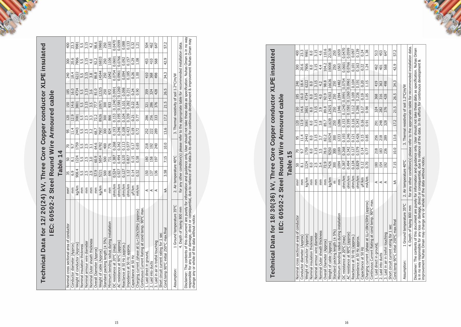
15 16
Tech
nica
l Dat
a fo
r 12
/20(
24)
kV, T
hree
Cor
e C
oppe
r co
nduc
tor
XLP
E in
sula
ted
IEC
: 60
502-
2 St
eel R
ound
Wir
e A
rmou
red
cabl
e Ta
ble
14
Dis
clai
mer
: Th
e co
nten
ts o
f th
is d
ocum
ent
are
pure
ly fo
r in
form
atio
n an
d gu
idan
ce o
nly.
Use
r sh
ould
not
tak
e th
ese
data
as
spec
ifica
tion.
Nuh
as O
man
is in
no
way
re
spon
sibl
e fo
r an
y lo
ss o
r da
mag
e, d
irect
or
cons
ique
ntia
l, du
e to
rel
ianc
e of
the
dat
a.In
its
effo
rts
for
cont
inuo
us d
evel
opm
ent
& im
prov
emen
t N
uhas
Om
an m
ay
chan
ge a
ny o
r w
hole
of
the
data
with
out
notic
e.
Assu
mpt
ion:
1
Gro
und
tem
pera
ture
35°
C 2.
Air
tem
pera
ture
40°
C
3. T
herm
al r
esis
tivity
of
soil
1.2°
C/m
/W
4.
Dep
th o
f la
ying
800
mm
fo
r an
y ot
her
cond
ition
(s)
plea
se r
efer
to
the
appr
opria
te t
able
for
reco
mm
ende
d in
stal
latio
n da
ta.
Nom
inal
cro
ss s
ectio
nal a
rea
of c
ondu
ctor
m
m2
35
50
70
95
120
150
185
240
300
400
Cond
ucto
r di
amet
er (
Appr
ox)
m
m
6.9
8.1
9.7
11.4
12
.9
14.6
16
.0
18.4
20
.6
23.3
W
eigh
t of
con
duct
or (
Appr
ox)
kg/k
m
908.
4 12
24
1759
24
43
3081
38
01
4734
62
22
7806
99
81
Nom
inal
insu
latio
n th
ickn
ess
mm
5.
5 5.
5 5.
5 5.
5 5.
5 5.
5 5.
5 5.
5 5.
5 5.
5 N
omin
al a
rmou
r w
ire d
iam
eter
m
m
2.5
2.5
2.5
2.5
2.5
3.15
3.
15
3.15
3.
15
3.15
N
omin
al O
uter
she
ath
thic
knes
s m
m
2.9
3.0
3.1
3.2
3.3
3.5
3.6
3.8
4.0
4.2
Ove
rall
Dia
met
er (
Appr
ox)
mm
57
.9
60.9
64
.6
68.7
72
.2
77.7
81
.0
86.8
92
.2
98.6
W
eigh
t of
cab
le (
Appr
ox)
kg/k
m
5221
58
54
6782
79
07
8926
10
971
1232
5 14
544
1683
3 19
865
Stan
dard
pac
king
leng
th (
± 5
%)
m
500
500
400
300
300
300
250
250
250
250
Min
imum
ben
ding
rad
ius
durin
g in
stal
latio
n m
m
696
731
776
824
866
933
972
1042
11
06
1183
D
C re
sist
ance
at
20°C
(m
ax)
ohm
/km
0.
524
0.38
7 0.
268
0.19
3 0.
153
0.12
40
0.09
91
0.07
54
0.06
01
0.04
70
AC r
esis
tanc
e at
90°
C (a
ppro
x)
ohm
/km
0.
927
0.49
4 0.
342
0.24
6 0.
195
0.15
81
0.12
60
0.09
61
0.07
66
0.05
99
Reac
tanc
e at
50
Hz
(app
rox.
) oh
m/k
m
0.12
7 0.
120
0.11
3 0.
108
0.10
4 0.
101
0.09
8 0.
094
0.09
2 0.
088
Impe
danc
e at
50
Hz
appr
ox.
ohm
/km
1.
12
0.82
7 0.
577
0.42
3 0.
339
0.28
2 0.
231
0.18
5 0.
157
0.13
3 Ca
paci
tanc
e at
50
Hz
μF/k
m
0.14
0.
15
0.17
0.
19
0.21
0.
22
0.24
0.
26
0.29
0.
32
Char
ging
cur
rent
/ph
ase
at U
o=12
kV,5
0Hz
(app
rox)
m
A/km
0.
52
0.58
0.
65
0.72
0.
77
0.84
0.
90
1.00
1.
08
1.21
Co
ntin
uous
Cur
rent
Rat
ing
at c
ond
tem
p. 9
0°C
max
. 1.
Lai
d di
rect
in g
roun
d,
A 15
0 18
0 21
8 25
2 28
6 32
1 35
9 41
0 45
3 50
4 2.
Lai
d in
to d
ucts
A
137
158
192
222
256
286
324
368
410
462
3. L
aid
in a
ir in
tre
foil
touc
hing
A
136
197
240
289
333
376
428
498
568
647
Shor
t ci
rcui
t cu
rren
t ra
ting
for
1 se
c Co
nd.t
emp
90°C
initi
al 2
50°C
max
.fina
l
kA
3.58
7.
15
10.0
13
.6
17.2
21
.5
26.5
34
.3
42.9
57
.2
Tech
nica
l Dat
a fo
r 18
/30(
36)
kV, T
hree
Cor
e Co
pper
con
duct
or X
LPE
insu
late
d IE
C: 6
0502
-2 S
teel
Rou
nd W
ire
Arm
oure
d ca
ble
Tabl
e 15
Dis
clai
mer
: Th
e co
nten
ts o
f th
is d
ocum
ent
are
pure
ly fo
r in
form
atio
n an
d gu
idan
ce o
nly.
Use
r sh
ould
not
tak
e th
ese
data
as
spec
ifica
tion.
Nuh
as O
man
is
in n
o w
ay r
espo
nsib
le fo
r an
y lo
ss o
r da
mag
e, d
irect
or
cons
ique
ntia
l, du
e to
rel
ianc
e of
the
dat
a. I
n its
effo
rts
for
cont
inuo
us d
evel
opm
ent
&
impr
ovem
ent
Nuh
as O
man
may
cha
nge
any
or w
hole
of
the
data
with
out
notic
e.
Assu
mpt
ion:
1
Gro
und
tem
pera
ture
35°
C 2.
Air
tem
pera
ture
40°
C 3.
The
rmal
res
istiv
ity o
f so
il 1.
2°C/
m/W
4. D
epth
of
layi
ng 8
00 m
m
for
any
othe
r co
nditi
on(s
) pl
ease
ref
er t
o th
e ap
prop
riate
tab
le fo
r re
com
men
ded
inst
alla
tion
data
.
Nom
inal
cro
ss s
ectio
nal a
rea
of c
ondu
ctor
m
m2
50
70
95
120
150
185
240
300
400
Cond
ucto
r di
amet
er (
Appr
ox)
m
m
8.1
9.7
11.4
12
.9
14.6
16
.0
18.4
20
.6
23.3
W
eigh
t of
con
duct
or (
Appr
ox)
kg/k
m
1224
17
59
2443
30
81
3801
47
34
6222
78
06
9981
N
omin
al in
sula
tion
thic
knes
s m
m
8.0
8.0
8.0
8.0
8.0
8.0
8.0
8.0
8.0
Nom
inal
arm
our
wire
dia
met
er
mm
2.
5 3.
15
3.15
3.
15
3.15
3.
15
3.15
3.
15
3.15
N
omin
al O
uter
she
ath
thic
knes
s m
m
3.4
3.5
3.7
3.8
3.9
4.0
4.2
4.4
4.6
Ove
rall
Dia
met
er (
Appr
ox)
mm
72
.9
78.0
82
.2
85.7
89
.8
92.9
98
.8
104.
2 11
0.6
Wei
ght
of c
able
(Ap
prox
) kg
/km
74
26
9250
10
524
1163
9 12
925
1430
3 16
636
1900
8 22
138
Stan
dard
pac
king
leng
th (
± 5
%)
m
300
300
300
250
250
250
250
250
250
Min
imum
ben
ding
rad
ius
durin
g in
stal
latio
n m
m
1094
11
69
1233
12
86
1346
13
94
1482
15
63
1659
D
C re
sist
ance
at
20°C
(m
ax)
ohm
/km
0.
387
0.26
8 0.
193
0.15
3 0.
1240
0.
0991
0.
0754
0.
0601
0.
0470
AC
res
ista
nce
at 9
0°C
(app
rox)
oh
m/k
m
0.49
4 0.
342
0.24
6 0.
195
0.15
81
0.12
60
0.09
61
0.07
66
0.05
99
Reac
tanc
e at
50
Hz
(app
rox.
) oh
m/k
m
0.13
4 0.
127
0.12
1 0.
116
0.11
2 0.
109
0.10
4 0.
101
0.09
7 Im
peda
nce
at 5
0 H
z ap
prox
. oh
m/k
m
0.82
9 0.
579
0.42
6 0.
343
0.28
6 0.
236
0.19
1 0.
163
0.13
9 Ca
paci
tanc
e at
50
Hz
μF/k
m
0.12
0.
14
0.15
0.
16
0.17
0.
19
0.20
0.
22
0.24
Ch
argi
ng c
urre
nt /
phas
e at
Uo=
18kV
,50H
z (a
ppro
x)
mA/
km
0.70
0.
77
0.85
0.
91
0.98
1.
05
1.15
1.
24
1.38
Co
ntin
uous
Cur
rent
Rat
ing
at c
ond
tem
p. 9
0°C
max
. 1.
Lai
d di
rect
in g
roun
d,
A 18
0 21
8 25
6 29
1 32
4 36
8 41
9 46
2 51
3 2.
Lai
d in
to d
ucts
A
154
183
218
248
282
316
363
401
453
3. L
aid
in a
ir in
tre
foil
touc
hing
A
192
236
289
328
376
428
498
568
647
Shor
t ci
rcui
t cu
rren
t ra
ting
for
1 se
c Co
nd.t
emp
90°C
initi
al 2
50°C
max
.fina
l
kA
7.15
10
.0
13.6
17
.2
21.5
26
.5
34.3
42
.9
57.2

17 18
Tech
nica
l Dat
a fo
r 3.
6/6(
7.2)
kV
, Thr
ee C
ore
Cop
per
cond
ucto
r X
LPE
insu
late
d IE
C:
6050
2-2
Un-
Arm
oure
d ca
ble
Tabl
e 16
Dis
clai
mer
: Th
e co
nten
ts o
f th
is d
ocum
ent
are
pure
ly fo
r in
form
atio
n an
d gu
idan
ce o
nly.
Use
r sh
ould
not
tak
e th
ese
data
as
spec
ifica
tion.
Nuh
as O
man
is in
no
way
res
pons
ible
for
any
loss
or
dam
age,
dire
ct o
r co
nsiq
uent
ial,
due
to r
elia
nce
of t
he d
ata.
In it
s ef
fort
s fo
r co
ntin
uous
dev
elop
men
t &
impr
ovem
ent
Nuh
as O
man
may
cha
nge
any
or w
hole
of
the
data
with
out
notic
e.
Assu
mpt
ion:
1
Gro
und
tem
pera
ture
35°
C 2.
Air
tem
pera
ture
40°
C 3.
The
rmal
res
istiv
ity o
f so
il 1.
2°C/
m/W
4. D
epth
of
layi
ng 8
00 m
m
for
any
othe
r co
nditi
on(s
) pl
ease
ref
er t
o th
e ap
prop
riate
tab
le fo
r re
com
men
ded
inst
alla
tion
data
.
Nom
inal
cro
ss s
ectio
nal a
rea
of c
ondu
ctor
m
m2
16
25
35
50
70
95
120
150
185
240
300
400
Cond
ucto
r di
amet
er (
Appr
ox)
m
m
4.8
5.9
6.9
8.1
9.7
11.4
12
.9
14.6
16
.0
18.4
20
.6
23.3
W
eigh
t of
con
duct
or (
Appr
ox)
kg/k
m
414
655
908.
4 12
24
1759
24
43
3081
38
01
4734
62
22
7806
99
81
Nom
inal
insu
latio
n th
ickn
ess
mm
2.
8 2.
8 2.
8 2.
8 2.
8 2.
8 2.
8 2.
8 2.
8 2.
8 2.
8 2.
8 N
omin
al O
uter
she
ath
thic
knes
s m
m
2.1
2.2
2.2
2.3
2.5
2.6
2.7
2.8
2.9
3.1
3.3
3.5
Ove
rall
Dia
met
er (
Appr
ox)
mm
33
.3
35.9
38
.2
41.1
45
.0
49.1
52
.6
56.6
59
.8
65.7
71
.0
77.5
W
eigh
t of
cab
le (
Appr
ox)
kg/k
m
1229
15
71
1902
23
40
3046
39
05
4697
56
04
6687
84
74
1034
9 12
881
Stan
dard
pac
king
leng
th (
± 5
%)
m
500
500
500
500
500
500
400
400
300
250
250
250
Min
imum
ben
ding
rad
ius
durin
g in
stal
latio
n m
m
500
539
572
616
675
736
789
849
897
985
1066
11
62
DC
resi
stan
ce a
t 20
°C (
max
) oh
m/k
m
1.15
0.
727
0.52
4 0.
387
0.26
8 0.
193
0.15
3 0.
1240
0.
0991
0.
0754
0.
0601
0.
0470
AC
res
ista
nce
at 9
0°C
(app
rox)
oh
m/k
m
1.47
0.
927
0.66
8 0.
494
0.34
2 0.
246
0.19
5 0.
1581
0.
1260
0.
0961
0.
0766
0.
0599
Re
acta
nce
at 5
0 H
z (a
ppro
x.)
ohm
/km
0.
1151
0.
1074
0.
102
0.09
7 0.
092
0.08
9 0.
086
0.08
4 0.
082
0.08
0 0.
078
0.07
6 Im
peda
nce
at 5
0 H
z ap
prox
. oh
m/k
m
2.44
1.
54
1.11
0.
824
0.57
3 0.
418
0.33
4 0.
276
0.22
5 0.
178
0.15
0 0.
125
Capa
cita
nce
at 5
0 H
z μF
/km
0.
18
0.21
0.
23
0.26
0.
30
0.34
0.
37
0.40
0.
44
0.49
0.
54
0.61
Ch
argi
ng c
urre
nt /
phas
e at
Uo=
3.6k
V,50
Hz
(app
rox)
m
A/km
0.
20
0.23
0.
26
0.30
0.
34
0.38
0.
42
0.45
0.
50
0.55
0.
61
0.69
Co
ntin
uous
Cur
rent
Rat
ing
at c
ond
tem
p. 9
0°C
max
. 1.
Lai
d di
rect
in g
roun
d,
A 10
3 12
5 15
5 19
0 23
1 27
2 30
8 34
4 39
0 44
4 49
0 54
3 2.
Lai
d in
to d
ucts
A
91
123
142
163
194
231
262
300
335
385
425
480
3. L
aid
in a
ir in
tre
foil
touc
hing
A
91
119
144
200
245
300
341
391
446
518
591
673
Shor
t ci
rcui
t cu
rren
t ra
ting
for
1 se
c Co
nd.t
emp
90°C
initi
al 2
50°C
max
.fina
l
kA
2.29
3.
58
5.00
7.
15
10.0
13
.6
17.2
21
.5
26.5
34
.3
42.9
57
.2
Tech
nica
l Dat
a fo
r 6/
10(1
2) k
V, T
hree
Cor
e C
oppe
r co
nduc
tor
XLP
E in
sula
ted
IEC
: 60
502-
2 U
n-A
rmou
red
cabl
e Ta
ble
17
Dis
clai
mer
: Th
e co
nten
ts o
f th
is d
ocum
ent
are
pure
ly fo
r in
form
atio
n an
d gu
idan
ce o
nly.
Use
r sh
ould
not
tak
e th
ese
data
as
spec
ifica
tion.
Nuh
as O
man
is in
no
way
res
pons
ible
for
any
loss
or
dam
age,
dire
ct o
r co
nsiq
uent
ial,
due
to r
elia
nce
of t
he d
ata.
In it
s ef
fort
s fo
r co
ntin
uous
dev
elop
men
t &
impr
ovem
ent
Nuh
as O
man
may
cha
nge
any
or w
hole
of
the
dat
a w
ithou
t no
tice.
Assu
mpt
ion:
1
Gro
und
tem
pera
ture
35°
C 2.
Air
tem
pera
ture
40°
C 3.
The
rmal
res
istiv
ity o
f so
il 1.
2°C/
m/W
4. D
epth
of
layi
ng 8
00 m
m
for
any
othe
r co
nditi
on(s
) pl
ease
ref
er t
o th
e ap
prop
riate
tab
le fo
r re
com
men
ded
inst
alla
tion
data
.
Nom
inal
cro
ss s
ectio
nal a
rea
of c
ondu
ctor
m
m2
16
25
35
50
70
95
120
150
185
240
300
400
Cond
ucto
r di
amet
er (
Appr
ox)
m
m
4.8
5.9
6.9
8.1
9.7
11.4
12
.9
14.6
16
.0
18.4
20
.6
23.3
W
eigh
t of
con
duct
or (
Appr
ox)
kg/k
m
414
654.
9 90
8.4
1224
17
59
2443
30
81
3801
47
34
6222
78
06
9981
N
omin
al in
sula
tion
thic
knes
s m
m
3.4
3.4
3.4
3.4
3.4
3.4
3.4
3.4
3.4
3.4
3.4
3.4
Nom
inal
Out
er s
heat
h th
ickn
ess
mm
2.
2 2.
3 2.
4 2.
5 2.
6 2.
7 2.
8 3.
0 3.
1 3.
3 3.
4 3.
7 O
vera
ll D
iam
eter
(Ap
prox
) m
m
37.5
40
.2
42.6
45
.5
49.3
53
.3
56.8
61
.1
64.3
70
.2
75.3
81
.9
Wei
ght
of c
able
(Ap
prox
) kg
/km
14
32
1797
21
59
2604
33
20
4201
50
10
5968
70
69
8890
10
761
1336
5 St
anda
rd p
acki
ng le
ngth
(±
5%
) m
50
0 50
0 50
0 50
0 50
0 50
0 40
0 30
0 30
0 25
0 25
0 25
0 M
inim
um b
endi
ng r
adiu
s du
ring
inst
alla
tion
mm
56
2 60
3 63
9 68
2 73
9 80
0 85
3 91
6 96
4 10
52
1130
12
29
DC
resi
stan
ce a
t 20
°C (
max
) oh
m/k
m
1.15
0.
727
0.52
4 0.
387
0.26
8 0.
193
0.15
3 0.
1240
0.
0991
0.
0754
0.
0601
0.
0470
AC
res
ista
nce
at 9
0°C
(app
rox)
oh
m/k
m
1.47
0.
927
0.66
8 0.
494
0.34
2 0.
246
0.19
5 0.
1581
0.
1260
0.
0961
0.
0766
0.
0599
Re
acta
nce
at 5
0 H
z (a
ppro
x.)
ohm
/km
0.
126
0.11
7 0.
111
0.10
5 0.
100
0.09
6 0.
093
0.09
0 0.
088
0.08
5 0.
083
0.08
0 Im
peda
nce
at 5
0 H
z ap
prox
. oh
m/k
m
2.44
1.
54
1.11
0.
825
0.57
4 0.
420
0.33
6 0.
278
0.22
7 0.
181
0.15
2 0.
128
Capa
cita
nce
at 5
0 H
z μF
/km
0.
15
0.17
0.
19
0.21
0.
24
0.27
0.
29
0.32
0.
34
0.38
0.
42
0.47
Ch
argi
ng c
urre
nt /
phas
e at
Uo=
6kV,
50H
z (a
ppro
x)
mA/
km
0.28
0.
32
0.36
0.
40
0.45
0.
50
0.55
0.
60
0.65
0.
72
0.79
0.
89
Cont
inuo
us C
urre
nt R
atin
g at
con
d te
mp.
90°
C m
ax.
1. L
aid
dire
ct in
gro
und,
A
103
125
155
190
231
272
308
344
390
444
490
543
2. L
aid
into
duc
ts
A 91
12
3 14
2 16
3 19
4 23
1 26
2 30
0 33
5 38
5 42
5 48
0 3.
Lai
d in
air
in t
refo
il to
uchi
ng
A 91
11
9 14
4 20
0 24
5 30
0 34
1 39
1 44
6 51
8 59
1 67
3 Sh
ort
circ
uit
curr
ent
ratin
g fo
r 1
sec
Co
nd.t
emp
90°C
initi
al 2
50°C
max
.fina
l
kA
2.29
3.
58
5.00
7.
15
10.0
13
.6
17.2
21
.5
26.5
34
.3
42.9
57
.2

19 20
Tech
nica
l Dat
a fo
r 8.
7/15
(17.
5) k
V, T
hree
Cor
e C
oppe
r co
nduc
tor
XLP
E in
sula
ted
IE
C:
6050
2-2
Un-
Arm
oure
d ca
ble
Tabl
e 18
Dis
clai
mer
: Th
e co
nten
ts o
f th
is d
ocum
ent
are
pure
ly fo
r in
form
atio
n an
d gu
idan
ce o
nly.
Use
r sh
ould
not
tak
e th
ese
data
as
spec
ifica
tion.
Nuh
as O
man
is in
no
way
res
pons
ible
fo
r an
y lo
ss o
r da
mag
e, d
irect
or
cons
ique
ntia
l, du
e to
rel
ianc
e of
the
dat
a.In
its
effo
rts
for
cont
inuo
us d
evel
opm
ent
& im
prov
emen
t N
uhas
Om
an m
ay c
hang
e an
y or
who
le
of t
he d
ata
with
out
notic
e.
Assu
mpt
ion:
1
Gro
und
tem
pera
ture
35°
C 2.
Air
tem
pera
ture
40°
C 3.
The
rmal
res
istiv
ity o
f so
il 1.
2°C/
m/W
4. D
epth
of
layi
ng 8
00 m
m
for
any
othe
r co
nditi
on(s
) pl
ease
ref
er t
o th
e ap
prop
riate
tab
le fo
r re
com
men
ded
inst
alla
tion
data
.
Nom
inal
cro
ss s
ectio
nal a
rea
of c
ondu
ctor
m
m2
25
35
50
70
95
120
150
185
240
300
400
Cond
ucto
r di
amet
er (
Appr
ox)
m
m
5.9
6.9
8.1
9.7
11.4
12
.9
14.6
16
.0
18.4
20
.6
23.3
W
eigh
t of
con
duct
or (
Appr
ox)
kg/k
m
655
908
1224
17
59
2443
30
81
3801
47
34
6222
78
06
9981
N
omin
al in
sula
tion
thic
knes
s m
m
4.5
4.5
4.5
4.5
4.5
4.5
4.5
4.5
4.5
4.5
4.5
Nom
inal
Out
er s
heat
h th
ickn
ess
mm
2.
5 2.
5 2.
6 2.
8 2.
9 3.
0 3.
1 3.
3 3.
4 3.
6 3.
8 O
vera
ll D
iam
eter
(Ap
prox
) m
m
45.5
47
.8
50.6
54
.6
58.6
62
.2
66.1
69
.6
75.3
80
.5
87.0
W
eigh
t of
cab
le (
Appr
ox)
kg/k
m
2109
24
76
2939
37
05
4600
54
47
6388
75
57
9383
11
306
1391
4 St
anda
rd p
acki
ng le
ngth
(±
5%
) m
50
0 50
0 50
0 50
0 40
0 40
0 30
0 25
0 25
0 25
0 25
0 M
inim
um b
endi
ng r
adiu
s du
ring
inst
alla
tion
mm
68
2 71
6 75
9 81
9 87
9 93
3 99
2 10
44
1130
12
08
1305
D
C re
sist
ance
at
20°C
(m
ax)
ohm
/km
0.
727
0.52
4 0.
387
0.26
8 0.
193
0.15
3 0.
1240
0.
0991
0.
0754
0.
0601
0.
0470
AC
res
ista
nce
at 9
0°C
(app
rox)
oh
m/k
m
1.47
0.
927
0.49
4 0.
342
0.24
6 0.
195
0.15
81
0.12
60
0.09
61
0.07
66
0.05
99
Reac
tanc
e at
50
Hz
(app
rox.
) oh
m/k
m
0.12
6 0.
120
0.11
3 0.
107
0.10
2 0.
099
0.09
6 0.
093
0.09
0 0.
087
0.08
4 Im
peda
nce
at 5
0 H
z ap
prox
. oh
m/k
m
1.54
1.
11
0.82
6 0.
576
0.42
1 0.
338
0.28
0 0.
229
0.18
3 0.
155
0.13
0 Ca
paci
tanc
e at
50
Hz
μF/k
m
0.14
0.
16
0.18
0.
20
0.22
0.
24
0.26
0.
28
0.31
0.
34
0.38
Ch
argi
ng c
urre
nt /
phas
e at
Uo=
8.7k
V,50
Hz
(app
rox)
m
A/km
0.
39
0.43
0.
49
0.54
0.
60
0.65
0.
71
0.77
0.
85
0.92
1.
04
Cont
inuo
us C
urre
nt R
atin
g at
con
d te
mp.
90°
C m
ax.
1. L
aid
dire
ct in
gro
und,
A
125
155
190
231
272
308
344
390
444
490
543
2. L
aid
into
duc
ts
A 12
3 14
2 16
3 19
4 23
1 26
2 30
0 33
5 38
5 42
5 48
0 3.
Lai
d in
air
in t
refo
il to
uchi
ng
A 11
9 14
4 20
0 24
5 30
0 34
1 39
1 44
6 51
8 59
1 67
3 Sh
ort
circ
uit
curr
ent
ratin
g fo
r 1
sec
Cond
.tem
p 90
°C in
itial
250
°C m
ax.fi
nal
kA
2.
29
3.58
7.
15
10.0
13
.6
17.2
21
.5
26.5
34
.3
42.9
57
.2
Tech
nica
l Dat
a fo
r 12
/20(
24)
kV, T
hree
Cor
e C
oppe
r co
nduc
tor
XLP
E in
sula
ted
IEC
: 60
502-
2 U
n-A
rmou
red
cabl
e Ta
ble
19
Dis
clai
mer
: Th
e co
nten
ts o
f th
is d
ocum
ent
are
pure
ly fo
r in
form
atio
n an
d gu
idan
ce o
nly.
Use
r sh
ould
not
tak
e th
ese
data
as
spec
ifica
tion.
Nuh
as O
man
is in
no
way
re
spon
sibl
e fo
r an
y lo
ss o
r da
mag
e, d
irect
or
cons
ique
ntia
l, du
e to
rel
ianc
e of
the
dat
a.In
its
effo
rts
for
cont
inuo
us d
evel
opm
ent
& im
prov
emen
t N
uhas
Om
an m
ay
chan
ge a
ny o
r w
hole
of
the
data
with
out
notic
e.
Assu
mpt
ion:
1
Gro
und
tem
pera
ture
35°
C 2.
Air
tem
pera
ture
40°
C 3.
The
rmal
res
istiv
ity o
f so
il 1.
2°C/
m/W
4. D
epth
of
layi
ng 8
00 m
m
for
any
othe
r co
nditi
on(s
) pl
ease
ref
er t
o th
e ap
prop
riate
tab
le fo
r re
com
men
ded
inst
alla
tion
data
.
Nom
inal
cro
ss s
ectio
nal a
rea
of c
ondu
ctor
m
m2
35
50
70
95
120
150
185
240
300
400
Cond
ucto
r di
amet
er (
Appr
ox)
m
m
6.9
8.1
9.7
11.4
12
.9
14.6
16
.0
18.4
20
.6
23.3
W
eigh
t of
con
duct
or (
Appr
ox)
kg/k
m
908.
4 12
24
1759
24
43
3081
38
01
4734
62
22
7806
99
81
Nom
inal
insu
latio
n th
ickn
ess
mm
5.
5 5.
5 5.
5 5.
5 5.
5 5.
5 5.
5 5.
5 5.
5 5.
5 N
omin
al O
uter
she
ath
thic
knes
s m
m
2.7
2.8
2.9
3.1
3.2
3.3
3.4
3.6
3.8
4.0
Ove
rall
Dia
met
er (
Appr
ox)
mm
52
.57
55.5
59
.2
63.5
67
.0
71.0
74
.3
80.1
85
.5
91.9
W
eigh
t of
cab
le (
Appr
ox)
kg/k
m
2808
33
01
4053
50
14
5868
68
49
8006
98
84
1185
9 14
508
Stan
dard
pac
king
leng
th (
± 5
%)
m
500
500
400
300
300
300
250
250
250
250
Min
imum
ben
ding
rad
ius
durin
g in
stal
latio
n m
m
789
833
889
952
1005
10
66
1115
12
02
1282
13
79
DC
resi
stan
ce a
t 20
°C (
max
) oh
m/k
m
0.52
4 0.
387
0.26
8 0.
193
0.15
3 0.
1240
0.
0991
0.
0754
0.
0601
0.
0470
AC
res
ista
nce
at 9
0°C
(app
rox)
oh
m/k
m
0.92
7 0.
494
0.34
2 0.
246
0.19
5 0.
1581
0.
1260
0.
0961
0.
0766
0.
0599
Re
acta
nce
at 5
0 H
z (a
ppro
x.)
ohm
/km
0.
127
0.12
0 0.
113
0.10
8 0.
104
0.10
1 0.
098
0.09
4 0.
092
0.08
8 Im
peda
nce
at 5
0 H
z ap
prox
. oh
m/k
m
1.12
0.
827
0.57
7 0.
423
0.33
9 0.
282
0.23
1 0.
185
0.15
7 0.
133
Capa
cita
nce
at 5
0 H
z μF
/km
0.
14
0.15
0.
17
0.19
0.
21
0.22
0.
24
0.26
0.
29
0.32
Ch
argi
ng c
urre
nt /
phas
e at
Uo=
12kV
,50H
z (a
ppro
x)
mA/
km
0.52
0.
58
0.65
0.
72
0.77
0.
84
0.90
1.
00
1.08
1.
21
Cont
inuo
us C
urre
nt R
atin
g at
con
d te
mp.
90°
C m
ax.
1. L
aid
dire
ct in
gro
und,
A
157
190
231
268
303
340
380
435
485
537
2. L
aid
into
duc
ts
A 13
9 16
8 20
4 23
5 27
2 30
3 34
4 39
0 43
3 48
6 3.
Lai
d in
air
in t
refo
il to
uchi
ng
A 14
0 20
4 25
0 30
0 34
6 39
1 44
6 51
8 59
1 67
3 Sh
ort
circ
uit
curr
ent
ratin
g fo
r 1
sec
Co
nd.t
emp
90°C
initi
al 2
50°C
max
.fina
l
kA
3.58
7.
15
10.0
13
.6
17.2
21
.5
26.5
34
.3
42.9
57
.2

21 22
Tech
nica
l Dat
a fo
r 18
/30(
36)
kV, T
hree
Cor
e Co
pper
con
duct
or X
LPE
insu
late
d IE
C: 6
0502
-2 U
n-A
rmou
red
cabl
e Ta
ble
20
Dis
clai
mer
: Th
e co
nten
ts o
f th
is d
ocum
ent
are
pure
ly fo
r in
form
atio
n an
d gu
idan
ce o
nly.
Use
r sh
ould
not
tak
e th
ese
data
as
spec
ifica
tion.
Nuh
as O
man
is
in n
o w
ay r
espo
nsib
le fo
r an
y lo
ss o
r da
mag
e, d
irect
or
cons
ique
ntia
l, du
e to
rel
ianc
e of
the
dat
a.In
its
effo
rts
for
cont
inuo
us d
evel
opm
ent
&
impr
ovem
ent
Nuh
as O
man
may
cha
nge
any
or w
hole
of
the
data
with
out
notic
e.
Assu
mpt
ion:
1
Gro
und
tem
pera
ture
35°
C 2.
Air
tem
pera
ture
40°
C 3.
The
rmal
res
istiv
ity o
f so
il 1.
2°C/
m/W
4. D
epth
of
layi
ng 8
00 m
m
for
any
othe
r co
nditi
on(s
) pl
ease
ref
er t
o th
e ap
prop
riate
tab
le fo
r re
com
men
ded
inst
alla
tion
data
.
Nom
inal
cro
ss s
ectio
nal a
rea
of c
ondu
ctor
m
m2
50
70
95
120
150
185
240
300
400
Cond
ucto
r di
amet
er (
Appr
ox)
m
m
8.1
9.7
11.4
12
.9
14.6
16
.0
18.4
20
.6
23.3
W
eigh
t of
con
duct
or (
Appr
ox)
kg/k
m
1224
17
59
2443
30
81
3801
47
34
6222
78
06
9981
N
omin
al in
sula
tion
thic
knes
s m
m
8.0
8.0
8.0
8.0
8.0
8.0
8.0
8.0
8.0
Nom
inal
Out
er s
heat
h th
ickn
ess
mm
3.
2 3.
3 3.
4 3.
6 3.
7 3.
8 4
4.2
4.4
Ove
rall
Dia
met
er (
Appr
ox)
mm
67
.5
71.3
75
.3
79.0
83
.1
86.2
92
.1
97.5
10
3.9
Wei
ght
of c
able
(Ap
prox
) kg
/km
43
07
5114
61
06
7049
80
91
9280
11
266
1332
3 16
070
Stan
dard
pac
king
leng
th (
± 5
%)
m
300
300
300
250
250
250
250
250
250
Min
imum
ben
ding
rad
ius
durin
g in
stal
latio
n m
m
1351
14
25
1506
15
80
1661
17
25
1842
19
49
2078
D
C re
sist
ance
at
20°C
(m
ax)
ohm
/km
0.
387
0.26
8 0.
193
0.15
3 0.
1249
0.
0991
0.
0754
0.
0601
0.
0470
AC
res
ista
nce
at 9
0°C
(app
rox)
oh
m/k
m
0.49
4 0.
342
0.24
6 0.
195
0.15
81
0.12
69
0.09
61
0.07
66
0.05
99
Reac
tanc
e at
50
Hz
(app
rox.
) oh
m/k
m
0.13
4 0.
127
0.12
1 0.
116
0.11
2 0.
109
0.10
4 0.
101
0.09
7 Im
peda
nce
at 5
0 H
z ap
prox
. oh
m/k
m
0.82
9 0.
579
0.42
6 0.
343
0.28
6 0.
236
0.19
1 0.
163
0.13
9 Ca
paci
tanc
e at
50
Hz
μF/k
m
0.12
0.
14
0.15
0.
16
0.17
0.
19
0.20
0.
22
0.24
Ch
argi
ng c
urre
nt /
phas
e at
Uo=
18kV
,50H
z (a
ppro
x)
mA/
km
0.70
0.
77
0.85
0.
91
0.98
1.
05
1.15
1.
24
1.38
Co
ntin
uous
Cur
rent
Rat
ing
at c
ond
tem
p. 9
0°C
max
. 1.
Lai
d di
rect
in g
roun
d,
A 19
0 23
1 26
8 30
3 34
0 38
0 43
5 48
5 53
7 2.
Lai
d in
to d
ucts
A
168
204
235
272
303
344
390
433
486
3. L
aid
in a
ir in
tre
foil
touc
hing
A
204
250
300
346
391
446
518
591
673
Shor
t ci
rcui
t cu
rren
t ra
ting
for
1 se
c
Cond
.tem
p 90
°C in
itial
250
°C m
ax.fi
nal
kA
7.
15
10.0
13
.6
17.2
21
.5
26.5
34
.3
42.9
57
.2
Tech
nica
l Dat
a fo
r 3.
6/6(
7.2)
kV
, Thr
ee C
ore
Copp
er c
ondu
ctor
XLP
E in
sula
ted
IEC:
605
02-2
Ste
el T
ape
Arm
oure
d ca
ble
Tabl
e 21
Dis
clai
mer
: Th
e co
nten
ts o
f th
is d
ocum
ent
are
pure
ly fo
r in
form
atio
n an
d gu
idan
ce o
nly.
Use
r sh
ould
not
tak
e th
ese
data
as
spec
ifica
tion.
Nuh
as O
man
is
in n
o w
ay r
espo
nsib
le fo
r an
y lo
ss o
r da
mag
e, d
irect
or
cons
ique
ntia
l ,du
e to
rel
ianc
e of
the
dat
a.In
its
effo
rts
for
cont
inuo
us d
evel
opm
ent
&
impr
ovem
ent
Nuh
as O
man
may
cha
nge
any
or w
hole
of
the
data
with
out
notic
e.
Assu
mpt
ion:
1
Gro
und
tem
pera
ture
35°
C 2.
Air
tem
pera
ture
40°
C 3.
The
rmal
res
istiv
ity o
f so
il 1.
2°C/
m/W
4. D
epth
of
layi
ng 8
00 m
m
for
any
othe
r co
nditi
on(s
) pl
ease
ref
er t
o th
e ap
prop
riate
tab
le fo
r re
com
men
ded
inst
alla
tion
data
.
Nom
inal
cro
ss s
ectio
nal a
rea
of c
ondu
ctor
m
m2
50
70
95
120
150
185
240
300
400
Cond
ucto
r di
amet
er (
Appr
ox)
m
m
8.1
9.7
11.4
12
.9
14.6
16
.0
18.4
20
.6
23.3
W
eigh
t of
con
duct
or (
Appr
ox)
kg/k
m
1224
17
59
2443
30
81
3801
47
34
6222
78
06
9981
N
omin
al in
sula
tion
thic
knes
s m
m
2.8
2.8
2.8
2.8
2.8
2.8
2.8
2.8
2.8
Nom
inal
ste
el t
ape
thic
knes
s m
m
0.5
0.5
0.5
0.5
0.5
0.5
0.5
0.5
0.8
Nom
inal
Out
er s
heat
h th
ickn
ess
mm
2.
4 2.
5 2.
7 2.
8 2.
9 3.
0 3.
2 3.
4 3.
6 O
vera
ll D
iam
eter
(Ap
prox
) m
m
43.3
47
.0
51.3
54
.8
58.8
62
.0
67.9
73
.2
80.9
W
eigh
t of
cab
le (
Appr
ox)
kg/k
m
3061
38
13
4769
56
25
6607
77
47
9641
11
613
1506
8 St
anda
rd p
acki
ng le
ngth
(±
5%
) m
50
0 50
0 50
0 40
0 40
0 30
0 25
0 25
0 25
0 M
inim
um b
endi
ng r
adiu
s du
ring
inst
alla
tion
mm
55
8 60
3 65
4 69
6 74
4 78
3 85
3 93
3 10
10
DC
resi
stan
ce a
t 20
°C (
max
) oh
m/k
m
0.38
7 0.
268
0.19
3 0.
153
0.12
40
0.09
91
0.07
54
0.06
01
0.04
70
AC r
esis
tanc
e at
90°
C (a
ppro
x)
ohm
/km
0.
494
0.34
2 0.
246
0.19
5 0.
1581
0.
1260
0.
0961
0.
0766
0.
0599
Re
acta
nce
at 5
0 H
z (a
ppro
x.)
ohm
/km
0.
097
0.09
2 0.
089
0.08
6 0.
084
0.08
2 0.
080
0.07
8 0.
076
Impe
danc
e at
50
Hz
appr
ox.
ohm
/km
0.
824
0.57
3 0.
418
0.33
4 0.
276
0.22
5 0.
178
0.15
0 0.
125
Capa
cita
nce
at 5
0 H
z μF
/km
0.
26
0.30
0.
34
0.37
0.
40
0.44
0.
49
0.54
0.
61
Char
ging
cur
rent
/ph
ase
at U
o=3.
6kV,
50H
z (a
ppro
x)
mA/
km
0.30
0.
34
0.38
0.
42
0.45
0.
50
0.55
0.
61
0.69
Co
ntin
uous
Cur
rent
Rat
ing
at c
ond
tem
p. 9
0°C
max
. 1.
Lai
d di
rect
in g
roun
d,
A 18
8 23
0 27
4 30
7 35
0 38
9 44
4 49
5 55
6 2.
Lai
d in
to d
ucts
A
188
222
260
291
321
350
401
427
453
3. L
aid
in a
ir in
tre
foil
touc
hing
A
219
271
328
376
428
481
568
647
734
Shor
t ci
rcui
t cu
rren
t ra
ting
for
1 se
c Co
nd.t
emp
90°C
initi
al 2
50°C
max
.fina
l kA
7.
15
10.0
13
.6
17.2
21
.5
26.5
34
.3
42.9
57
.2

23 24
Tech
nica
l Dat
a fo
r 6/
10(1
2) k
V, T
hree
Cor
e Co
pper
con
duct
or X
LPE
insu
late
d IE
C: 6
0502
-2 S
teel
Tap
e A
rmou
red
cabl
e Ta
ble
22
Dis
clai
mer
: Th
e co
nten
ts o
f th
is d
ocum
ent
are
pure
ly fo
r in
form
atio
n an
d gu
idan
ce o
nly.
Use
r sh
ould
not
tak
e th
ese
data
as
spec
ifica
tion.
Nuh
as O
man
is
in n
o w
ay r
espo
nsib
le fo
r an
y lo
ss o
r da
mag
e, d
irect
or
cons
ique
ntia
l ,du
e to
rel
ianc
e of
the
dat
a.In
its
effo
rts
for
cont
inuo
us d
evel
opm
ent
&
impr
ovem
ent
Nuh
as O
man
may
cha
nge
any
or w
hole
of
the
dat
a w
ithou
t no
tice
Assu
mpt
ion:
1
Gro
und
tem
pera
ture
35°
C 2.
Air
tem
pera
ture
40°
C 3.
The
rmal
res
istiv
ity o
f so
il 1.
2°C/
m/W
4. D
epth
of
layi
ng 8
00 m
m
for
any
othe
r co
nditi
on(s
) pl
ease
ref
er t
o th
e ap
prop
riate
tab
le fo
r re
com
men
ded
inst
alla
tion
data
.
Nom
inal
cro
ss s
ectio
nal a
rea
of c
ondu
ctor
m
m2
50
70
95
120
150
185
240
300
400
Cond
ucto
r di
amet
er (
Appr
ox)
m
m
8.1
9.7
11.4
12
.9
14.6
16
.0
18.4
20
.6
23.3
W
eigh
t of
con
duct
or (
Appr
ox)
kg/k
m
1224
17
59
2443
30
81
3801
47
34
6222
78
06
9981
N
omin
al in
sula
tion
thic
knes
s m
m
3.4
3.4
3.4
3.4
3.4
3.4
3.4
3.4
3.4
Nom
inal
ste
el t
ape
thic
knes
s m
m
0.5
0.5
0.5
0.5
0.5
0.5
0.5
0.5
0.8
Nom
inal
Out
er s
heat
h th
ickn
ess
mm
2.
5 2.
7 2.
8 2.
9 3.
0 3.
2 3.
3 3.
5 3.
8 O
vera
ll D
iam
eter
(Ap
prox
) m
m
47.5
51
.5
55.5
59
.0
63.1
66
.5
72.2
77
.5
85.3
W
eigh
t of
cab
le (
Appr
ox)
kg/k
m
3380
41
88
5143
60
17
7020
82
09
1010
2 12
103
1567
8 St
anda
rd p
acki
ng le
ngth
(±
5%
) m
50
0 50
0 50
0 40
0 30
0 30
0 25
0 25
0 25
0 M
inim
um b
endi
ng r
adiu
s du
ring
inst
alla
tion
mm
60
8 65
6 70
5 74
7 79
8 83
6 92
2 98
6 10
64
DC
resi
stan
ce a
t 20
°C (
max
) oh
m/k
m
0.38
7 0.
268
0.19
3 0.
153
0.12
40
0.09
91
0.07
54
0.06
01
0.04
70
AC r
esis
tanc
e at
90°
C (a
ppro
x)
ohm
/km
0.
494
0.34
2 0.
246
0.19
5 0.
1581
0.
1260
0.
0961
0.
0766
0.
0599
Re
acta
nce
at 5
0 H
z (a
ppro
x.)
ohm
/km
0.
105
0.10
0 0.
096
0.09
3 0.
090
0.08
8 0.
085
0.08
3 0.
080
Impe
danc
e at
50
Hz
appr
ox.
ohm
/km
0.
825
0.57
4 0.
420
0.33
6 0.
278
0.22
7 0.
181
0.15
2 0.
128
Capa
cita
nce
at 5
0 H
z μF
/km
0.
21
0.24
0.
27
0.29
0.
32
0.34
0.
38
0.42
0.
47
Char
ging
cur
rent
/ph
ase
at U
o=6k
V,50
Hz
(app
rox)
m
A/km
0.
40
0.45
0.
50
0.55
0.
60
0.65
0.
72
0.79
0.
89
Cont
inuo
us C
urre
nt R
atin
g at
con
d te
mp.
90°
C m
ax.
1. L
aid
dire
ct in
gro
und,
A
188
230
274
307
350
389
444
495
556
2. L
aid
into
duc
ts
A 18
8 22
2 26
0 29
1 32
1 35
0 40
1 42
7 45
3 3.
Lai
d in
air
in t
refo
il to
uchi
ng
A 21
9 27
1 32
8 37
6 42
8 48
1 56
8 64
7 73
4 Sh
ort
circ
uit
curr
ent
ratin
g fo
r 1
sec
Cond
.tem
p 90
°C in
itial
250
°C m
ax.fi
nal
kA
7.
15
10.0
13
.6
21
.5
26.5
34
.3
42.9
57
.2
Tech
nica
l Dat
a fo
r 8.
7/15
(17.
5) k
V, T
hree
Cor
e Co
pper
con
duct
or X
LPE
insu
late
d IE
C: 6
0502
-2 S
teel
Tap
e Ar
mou
red
cabl
e Ta
ble
23
Dis
clai
mer
: Th
e co
nten
ts o
f th
is d
ocum
ent
are
pure
ly fo
r in
form
atio
n an
d gu
idan
ce o
nly.
Use
r sh
ould
not
tak
e th
ese
data
as
spec
ifica
tion.
Nuh
as O
man
is
in n
o w
ay r
espo
nsib
le fo
r an
y lo
ss o
r da
mag
e, d
irect
or
cons
ique
ntia
l, du
e to
rel
ianc
e of
the
dat
a.In
its
effo
rts
for
cont
inuo
us d
evel
opm
ent
&
impr
ovem
ent
Nuh
as O
man
may
cha
nge
any
or w
hole
of
the
dat
a w
ithou
t no
tice.
Assu
mpt
ion:
1
Gro
und
tem
pera
ture
35°
C 2.
Air
tem
pera
ture
40°
C 3.
The
rmal
res
istiv
ity o
f so
il 1.
2°C/
m/W
4. D
epth
of
layi
ng 8
00 m
m
for
any
othe
r co
nditi
on(s
) pl
ease
ref
er t
o th
e ap
prop
riate
tab
le fo
r re
com
men
ded
inst
alla
tion
data
.
Nom
inal
cro
ss s
ectio
nal a
rea
of c
ondu
ctor
m
m2
50
70
95
120
150
185
240
300
400
Cond
ucto
r di
amet
er (
Appr
ox)
m
m
8.1
9.7
11.4
12
.9
14.6
16
.0
18.4
20
.6
23.3
W
eigh
t of
con
duct
or (
Appr
ox)
kg/k
m
1224
17
59
2443
30
81
3801
47
34
6222
78
06
9981
N
omin
al in
sula
tion
thic
knes
s m
m
4.5
4.5
4.5
4.5
4.5
4.5
4.5
4.5
4.5
Nom
inal
ste
el t
ape
thic
knes
s m
m
0.5
0.5
0.5
0.5
0.5
0.5
0.5
0.8
0.8
Nom
inal
Out
er s
heat
h th
ickn
ess
mm
2.
7 2.
8 3.
0 3.
1 3.
2 3.
3 3.
5 3.
7 3.
9 O
vera
ll D
iam
eter
(Ap
prox
) m
m
52.8
56
.6
60.8
64
.4
68.3
71
.6
77.5
83
.9
90.4
W
eigh
t of
cab
le (
Appr
ox)
kg/k
m
3832
46
43
5637
65
50
7564
87
60
1072
5 13
582
1637
6 St
anda
rd p
acki
ng le
ngth
(±
5%
) m
50
0 50
0 40
0 40
0 30
0 25
0 25
0 25
0 25
0 M
inim
um b
endi
ng r
adiu
s du
ring
inst
alla
tion
mm
67
2 71
8 76
8 81
1 85
8 91
6 98
6 10
47
1124
D
C re
sist
ance
at
20°C
(m
ax)
ohm
/km
0.
387
0.26
8 0.
193
0.15
3 0.
1240
0.
0991
0.
0754
0.
0601
0.
0470
AC
res
ista
nce
at 9
0°C
(app
rox)
oh
m/k
m
0.49
4 0.
342
0.24
6 0.
195
0.15
81
0.12
60
0.09
61
0.07
66
0.05
99
Reac
tanc
e at
50
Hz
(app
rox.
) oh
m/k
m
0.11
3 0.
107
0.10
2 0.
099
0.09
6 0.
093
0.09
0 0.
087
0.08
4 Im
peda
nce
at 5
0 H
z ap
prox
. oh
m/k
m
0.82
6 0.
576
0.42
1 0.
338
0.28
0 0.
229
0.18
3 0.
155
0.13
0 Ca
paci
tanc
e at
50
Hz
μF/k
m
0.18
0.
20
0.22
0.
24
0.26
0.
28
0.31
0.
34
0.38
Ch
argi
ng c
urre
nt /
phas
e at
Uo=
8.7k
V,50
Hz
(app
rox)
m
A/km
0.
49
0.54
0.
60
0.65
0.
71
0.77
0.
85
0.92
1.
04
Cont
inuo
us C
urre
nt R
atin
g at
con
d te
mp.
90°
C m
ax.
1. L
aid
dire
ct in
gro
und,
A
188
230
274
307
350
389
444
495
556
2. L
aid
into
duc
ts
A 18
8 22
2 26
0 29
1 32
1 35
0 40
1 42
7 45
3 3.
Lai
d in
air
in t
refo
il to
uchi
ng
A 21
9 27
1 32
8 37
6 42
8 48
1 56
8 64
7 73
4 Sh
ort
circ
uit
curr
ent
ratin
g fo
r 1
sec
Co
nd.t
emp
90°C
initi
al 2
50°C
max
.fina
l
kA
7.15
10
.0
13.6
17
.2
21.5
26
.5
34.3
42
.9
57.2

25 26
Tech
nica
l Dat
a fo
r 12
/20(
24)
kV, T
hree
Cor
e Co
pper
con
duct
or X
LPE
insu
late
d IE
C: 6
0502
-2 S
teel
Tap
e A
rmou
red
cabl
e Ta
ble
24
Dis
clai
mer
: Th
e co
nten
ts o
f th
is d
ocum
ent
are
pure
ly fo
r in
form
atio
n an
d gu
idan
ce o
nly.
Use
r sh
ould
not
tak
e th
ese
data
as
spec
ifica
tion.
Nuh
as O
man
is
in n
o w
ay r
espo
nsib
le fo
r an
y lo
ss o
r da
mag
e, d
irect
or
cons
ique
ntia
l, du
e to
rel
ianc
e of
the
dat
a.In
its
effo
rts
for
cont
inuo
us d
evel
opm
ent
&
impr
ovem
ent
Nuh
as O
man
may
cha
nge
any
or w
hole
of
the
data
with
out
notic
e.
Assu
mpt
ion:
1
Gro
und
tem
pera
ture
35°
C 2.
Air
tem
pera
ture
40°
C 3.
The
rmal
res
istiv
ity o
f so
il 1.
2°C/
m/W
4. D
epth
of
layi
ng 8
00 m
m
for
any
othe
r co
nditi
on(s
) pl
ease
ref
er t
o th
e ap
prop
riate
tab
le fo
r re
com
men
ded
inst
alla
tion
data
.
Nom
inal
cro
ss s
ectio
nal a
rea
of c
ondu
ctor
m
m2
50
70
95
120
150
185
240
300
400
Cond
ucto
r di
amet
er (
Appr
ox)
m
m
8.1
9.7
11.4
12
.9
14.6
16
.0
18.4
20
.6
23.3
W
eigh
t of
con
duct
or (
Appr
ox)
kg/k
m
1224
17
59
2443
30
81
3801
47
34
6222
78
06
9981
N
omin
al in
sula
tion
thic
knes
s m
m
5.5
5.5
5.5
5.5
5.5
5.5
5.5
5.5
5.5
Nom
inal
ste
el t
ape
thic
knes
s m
m
0.5
0.5
0.5
0.5
0.5
0.5
0.5
0.8
0.8
Nom
inal
Out
er s
heat
h th
ickn
ess
mm
2.
9 3.
0 3.
1 3.
2 3.
4 3.
5 3.
7 3.
9 4.
1 O
vera
ll D
iam
eter
(Ap
prox
) m
m
57.7
61
.4
65.5
69
.0
73.2
76
.5
82.3
88
.9
95.3
W
eigh
t of
cab
le (
Appr
ox)
kg/k
m
4283
51
02
6108
70
24
8112
93
30
1131
2 14
274
1710
9 St
anda
rd p
acki
ng le
ngth
(±
5%
) m
50
0 40
0 30
0 30
0 30
0 25
0 25
0 25
0 25
0 M
inim
um b
endi
ng r
adiu
s du
ring
inst
alla
tion
mm
73
1 77
6 82
4 86
6 93
3 97
2 10
42
1106
11
83
DC
resi
stan
ce a
t 20
°C (
max
) oh
m/k
m
0.38
7 0.
268
0.19
3 0.
153
0.12
40
0.09
91
0.07
54
0.06
01
0.04
70
AC r
esis
tanc
e at
90°
C (a
ppro
x)
ohm
/km
0.
494
0.34
2 0.
246
0.19
5 0.
1581
0.
1260
0.
0961
0.
0766
0.
0599
Re
acta
nce
at 5
0 H
z (a
ppro
x.)
ohm
/km
0.
120
0.11
3 0.
108
0.10
4 0.
101
0.09
8 0.
094
0.09
2 0.
088
Impe
danc
e at
50
Hz
appr
ox.
ohm
/km
0.
827
0.57
7 0.
423
0.33
9 0.
282
0.23
1 0.
185
0.15
7 0.
133
Capa
cita
nce
at 5
0 H
z μF
/km
0.
15
0.17
0.
19
0.21
0.
22
0.24
0.
26
0.29
0.
32
Char
ging
cur
rent
/ph
ase
at U
o=12
kV,5
0Hz
(app
rox)
m
A/km
0.
58
0.65
0.
72
0.77
0.
84
0.90
1.
00
1.08
1.
21
Cont
inuo
us C
urre
nt R
atin
g at
con
d te
mp.
90°
C m
ax.
1. L
aid
dire
ct in
gro
und,
A
180
218
252
286
321
359
410
453
504
2. L
aid
into
duc
ts
A 15
8 19
2 22
2 25
6 28
6 32
4 36
8 41
0 46
2 3.
Lai
d in
air
in t
refo
il to
uchi
ng
A 19
7 24
0 28
9 33
3 37
6 42
8 49
8 56
8 64
7 Sh
ort
circ
uit
curr
ent
ratin
g fo
r 1
sec
Cond
.tem
p 90
°C in
itial
250
°C m
ax.fi
nal
kA
7.
15
10.0
13
.6
17.2
21
.5
26.5
34
.3
42.9
57
.2
Tech
nica
l Dat
a fo
r 18
/30(
36)
kV, T
hree
Cor
e Co
pper
con
duct
or X
LPE
insu
late
d IE
C: 6
0502
-2 S
teel
Tap
e A
rmou
red
cabl
e Ta
ble
25
Dis
clai
mer
: Th
e co
nten
ts o
f th
is d
ocum
ent
are
pure
ly fo
r in
form
atio
n an
d gu
idan
ce o
nly.
Use
r sh
ould
not
tak
e th
ese
data
as
spec
ifica
tion.
Nuh
as O
man
is
in n
o w
ay r
espo
nsib
le fo
r an
y lo
ss o
r da
mag
e, d
irect
or
cons
ique
ntia
l, du
e to
rel
ianc
e of
the
dat
a.In
its
effo
rts
for
cont
inuo
us d
evel
opm
ent
&
impr
ovem
ent
Nuh
as O
man
may
cha
nge
any
or w
hole
of
the
data
with
out
notic
e.
Assu
mpt
ion:
1
Gro
und
tem
pera
ture
35°
C 2.
Air
tem
pera
ture
40°
C 3.
The
rmal
res
istiv
ity o
f so
il 1.
2°C/
m/W
4. D
epth
of
layi
ng 8
00 m
m
for
any
othe
r co
nditi
on(s
) pl
ease
ref
er t
o th
e ap
prop
riate
tab
le fo
r re
com
men
ded
inst
alla
tion
data
.
Nom
inal
cro
ss s
ectio
nal a
rea
of c
ondu
ctor
m
m2
50
70
95
120
150
185
240
300
400
Cond
ucto
r di
amet
er (
Appr
ox)
m
m
8.1
9.7
11.4
12
.9
14.6
16
.0
18.4
20
.6
23.3
W
eigh
t of
con
duct
or (
Appr
ox)
kg/k
m
1224
17
59
2443
30
81
3801
47
34
6222
78
06
9981
N
omin
al in
sula
tion
thic
knes
s m
m
8.0
8.0
8.0
8.0
8.0
8.0
8.0
8.0
8.0
Nom
inal
ste
el t
ape
thic
knes
s m
m
0.5
0.5
0.5
0.5
0.5
0.5
0.8
0.8
0.8
Nom
inal
Out
er s
heat
h th
ickn
ess
mm
3.
3 3.
4 3.
5 3.
6 3.
8 3.
9 4.
1 4.
3 4.
5 O
vera
ll D
iam
eter
(Ap
prox
) m
m
69.7
73
.5
77.5
81
.0
85.3
88
.4
95.5
10
0.9
107.
3 W
eigh
t of
cab
le (
Appr
ox)
kg/k
m
5506
63
81
7448
84
17
9573
10
819
1387
3 16
083
1901
7 St
anda
rd p
acki
ng le
ngth
(±
5%
) m
30
0 30
0 30
0 25
0 25
0 25
0 25
0 25
0 25
0 M
inim
um b
endi
ng r
adiu
s du
ring
inst
alla
tion
mm
87
5 93
5 98
6 10
28
1077
11
15
1186
12
50
1327
D
C re
sist
ance
at
20°C
(m
ax)
ohm
/km
0.
387
0.26
8 0.
193
0.15
3 0.
1240
0.
0991
0.
0754
0.
0601
0.
0470
AC
res
ista
nce
at 9
0°C
(app
rox)
oh
m/k
m
0.49
4 0.
342
0.24
6 0.
195
0.15
81
0.12
60
0.09
61
0.07
66
0.05
99
Reac
tanc
e at
50
Hz
(app
rox.
) oh
m/k
m
0.13
4 0.
127
0.12
1 0.
116
0.11
2 0.
109
0.10
4 0.
101
0.09
7 Im
peda
nce
at 5
0 H
z ap
prox
. hm
/km
0.
829
0.57
9 0.
426
0.34
3 0.
286
0.23
6 0.
191
0.16
3 0.
139
Capa
cita
nce
at 5
0 H
z μF
/km
0.
12
0.14
0.
15
0.16
0.
17
0.19
0.
20
0.22
0.
24
Char
ging
cur
rent
/ph
ase
at U
o=18
kV,5
0Hz
(app
rox)
m
A/km
0.
70
0.77
0.
85
0.91
0.
98
1.05
1.
15
1.24
1.
38
Cont
inuo
us C
urre
nt R
atin
g at
con
d te
mp.
90°
C m
ax.
1. L
aid
dire
ct in
gro
und,
A
180
218
256
291
324
368
419
462
513
2. L
aid
into
duc
ts
A 15
4 18
3 21
8 24
8 28
2 31
6 36
3 40
1 45
3 3.
Lai
d in
air
in t
refo
il to
uchi
ng
A 19
2 23
6 28
9 32
8 37
6 42
8 49
8 56
8 64
7 Sh
ort
circ
uit
curr
ent
ratin
g fo
r 1
sec
Cond
.tem
p 90
°C in
itial
250
°C m
ax.fi
nal
kA
7.
15
10.0
13
.6
17.2
21
.5
26.5
34
.3
42.9
57
.2

27 28
Nom
inal
cro
ss s
ectio
nal a
rea
of c
ondu
ctor
m
m2
50
70
95
120
150
185
240
300
400
500
630
800
1000
Co
nduc
tor
diam
eter
(Ap
prox
)
mm
8.
1 9.
7 11
.4
12.9
14
.6
16.0
18
.4
20.6
23
.3
26.3
30
.0
34.1
4 38
.2
Wei
ght
of c
ondu
ctor
(Ap
prox
) kg
/km
12
5 18
2 25
1 31
7 39
0 49
3 64
6 80
3 10
27
1307
17
21
2188
27
59
Nom
inal
insu
latio
n th
ickn
ess
mm
2.
8 2.
8 2.
8 2.
8 2.
8 2.
8 2.
8 2.
8 2.
8 2.
8 2.
8 2.
8 2.
8 N
omin
al a
rmou
r w
ire d
iam
eter
m
m
2.0
2.0
2.0
2.0
2.0
2.0
2.0
2.0
2.0
2.5
2.5
2.5
2.5
Nom
inal
Out
er s
heat
h th
ickn
ess
mm
1.
8 1.
9 1.
9 2.
0 2.
0 2.
1 2.
2 2.
3 2.
4 2.
5 2.
6 2.
8 2.
9 O
vera
ll D
iam
eter
(Ap
prox
) m
m
25.2
27
.1
28.8
30
.6
32.3
33
.9
36.6
39
.2
42.1
46
.5
50.5
55
.2
59.6
W
eigh
t of
cab
le (
Appr
ox)
kg/k
m
796
931
1071
12
21
1366
15
43
1819
21
01
2465
30
50
3673
44
16
5243
St
anda
rd p
acki
ng le
ngth
(±
5%
) m
50
0 50
0 50
0 50
0 50
0 50
0 50
0 50
0 50
0 50
0 50
0 40
0 30
0 M
inim
um b
endi
ng r
adiu
s du
ring
inst
alla
tion
mm
37
8 40
6 43
2 45
9 48
5 50
9 54
9 58
8 63
2 69
7 75
7 82
8 89
4 D
C re
sist
ance
at
20°C
(m
ax)
ohm
/km
0.
641
0.44
3 0.
320
0.25
3 0.
2060
0.1
640
0.12
50
0.10
00
0.07
78
0.06
05
0.04
69
0.03
67
0.02
91
AC r
esis
tanc
e at
90°
C (a
ppro
x)
ohm
/km
0.
818
0.56
5 0.
408
0.32
3 0.
2630
0.2
090
0.16
00
0.12
80
0.09
90
0.07
70
0.06
00
0.04
70
0.03
70
Reac
tanc
e at
50
Hz
(app
rox.
) oh
m/k
m
0.09
7 0.
092
0.08
9 0.
086
0.08
4 0.
082
0.08
0 0.
078
0.07
6 0.
075
0.07
4 0.
073
0.07
3 Im
peda
nce
at 5
0 H
z ap
prox
. oh
m/k
m
0.82
4 0.
573
0.41
8 0.
334
0.27
6 0.
225
0.17
8 0.
150
0.12
5 0.
108
0.09
5 0.
087
0.08
2 Ca
paci
tanc
e at
50
Hz
μF/k
m
0.26
0.
30
0.34
0.
37
0.40
0.
44
0.49
0.
54
0.61
0.
65
0.68
0.
71
0.75
Ch
argi
ng c
urre
nt /
phas
e at
Uo=
3.6k
V,50
Hz
(app
rox)
m
A/km
0.
30
0.34
0.
38
0.42
0.
45
0.50
0.
55
0.61
0.
69
0.74
0.
77
0.81
0.
85
Cont
inuo
us C
urre
nt R
atin
g at
con
d te
mp.
90°
C m
ax.
1. L
aid
dire
ct in
gro
und,
A
145
180
214
239
269
303
346
389
436
487
547
598
649
2. L
aid
into
duc
ts
A 14
5 18
0 20
9 23
5 25
6 28
6 32
4 35
9 38
9 42
7 47
0 50
4 54
7 3.
Lai
d in
air
in t
refo
il to
uchi
ng
A 17
0 21
0 25
7 31
1 33
3 38
0 44
6 50
7 58
5 67
3 77
0 85
7 94
4 Sh
ort
circ
uit
curr
ent
ratin
g fo
r 1
sec
Cond
.tem
p 90
°C in
itial
250
°C m
ax.fi
nal
kA
4.
7 6.
6 8.
9 11
.3
14.1
17
.4
22.6
28
.2
37.6
47
.0
59.2
75
.2
94.0
Tech
nica
l Dat
a fo
r 3.
6/6(
7.2)
kV
,Sin
gle
Cor
e A
lum
iniu
m c
ondu
ctor
XLP
E in
sula
ted
IEC
: 60
502-
2 A
lum
iniu
m R
ound
Wir
e A
rmou
red
cabl
e Ta
ble
26
Dis
clai
mer
: Th
e co
nten
ts o
f th
is d
ocum
ent
are
pure
ly fo
r in
form
atio
n an
d gu
idan
ce o
nly.
Use
r sh
ould
not
tak
e th
ese
data
as
spec
ifica
tion.
Nuh
as O
man
is in
no
way
res
pons
ible
for
any
loss
or
dam
age,
dire
ct o
r co
nsiq
uent
ial,
due
to r
elia
nce
of t
he d
ata.
In it
s ef
fort
s fo
r co
ntin
uous
dev
elop
men
t &
impr
ovem
ent
Nuh
as O
man
may
cha
nge
any
or w
hole
of
the
data
with
out
notic
e.
Assu
mpt
ion:
1
Gro
und
tem
pera
ture
35°
C 2.
Air
tem
pera
ture
40°
C 3.
The
rmal
res
istiv
ity o
f so
il 1.
2°C/
m/W
4. D
epth
of
layi
ng 8
00 m
m
for
any
othe
r co
nditi
on(s
) pl
ease
ref
er t
o th
e ap
prop
riate
tab
le fo
r re
com
men
ded
inst
alla
tion
data
.
Nom
inal
cro
ss s
ectio
nal a
rea
of c
ondu
ctor
m
m2
50
70
95
120
150
185
240
300
400
500
630
800
1000
Co
nduc
tor
diam
eter
(Ap
prox
)
mm
8.
1 9.
7 11
.4
12.9
14
.6
16.0
18
.4
20.6
23
.3
26.3
30
.0
34.1
4 38
.2
Wei
ght
of c
ondu
ctor
(Ap
prox
) kg
/km
12
5 18
2 25
1 31
7 39
0 49
3 64
6 80
3 10
27
1307
17
21
2188
27
59
Nom
inal
insu
latio
n th
ickn
ess
mm
3.
4 3.
4 3.
4 3.
4 3.
4 3.
4 3.
4 3.
4 3.
4 3.
4 3.
4 3.
4 3.
4 N
omin
al a
rmou
r w
ire d
iam
eter
m
m
2.0
2.0
2.0
2.0
2.0
2.0
2.0
2.0
2.0
2.5
2.5
2.5
2.5
Nom
inal
Out
er s
heat
h th
ickn
ess
mm
1.
9 1.
9 2
2.0
2.1
2.2
2.2
2.3
2.4
2.6
2.7
2.8
3 O
vera
ll D
iam
eter
(Ap
prox
) m
m
27.3
28
.9
30.9
32
.5
34.4
36
.0
38.6
41
.0
44.1
48
.5
52.6
57
.0
61.7
W
eigh
t of
cab
le (
Appr
ox)
kg/k
m
908
1035
12
02
1336
15
02
1685
19
62
2242
26
26
3240
38
89
4609
54
79
Stan
dard
pac
king
leng
th (
± 5
%)
m
500
500
500
500
500
500
500
500
500
500
500
400
300
Min
imum
ben
ding
rad
ius
durin
g in
stal
latio
n m
m
409
433
464
487
516
540
578
615
661
728
789
855
925
DC
resi
stan
ce a
t 20
°C (
max
) oh
m/k
m
0.64
1 0.
443
0.32
0 0.
253
0.20
60 0
.164
0 0.
1250
0.
1000
0.
0778
0.
0605
0.
0469
0.
0367
0.
0291
AC
res
ista
nce
at 9
0°C
(app
rox)
oh
m/k
m
0.81
8 0.
565
0.40
8 0.
323
0.26
30 0
.209
0 0.
1600
0.
1280
0.
0990
0.
0770
0.
0600
0.
0470
0.
0370
Re
acta
nce
at 5
0 H
z (a
ppro
x.)
ohm
/km
0.
105
0.10
0 0.
096
0.09
3 0.
090
0.08
8 0.
085
0.08
3 0.
080
0.07
9 0.
077
0.07
5 0.
074
Impe
danc
e at
50
Hz
appr
ox.
ohm
/km
0.
825
0.57
4 0.
420
0.33
6 0.
278
0.22
7 0.
181
0.15
2 0.
128
0.11
0 0.
097
0.08
9 0.
083
Capa
cita
nce
at 5
0 H
z μF
/km
0.
21
0.24
0.
27
0.29
0.
32
0.34
0.
38
0.42
0.
47
0.52
0.
57
0.63
0.
70
Char
ging
cur
rent
/ph
ase
at U
o=6k
V,50
Hz
(app
rox)
m
A/km
0.
40
0.45
0.
50
0.55
0.
60
0.65
0.
72
0.79
0.
89
0.97
1.
08
1.20
1.
32
Cont
inuo
us C
urre
nt R
atin
g at
con
d te
mp.
90°
C m
ax.
1. L
aid
dire
ct in
gro
und,
A
145
180
214
239
269
303
346
389
436
487
547
598
649
2. L
aid
into
duc
ts
A 14
5 18
0 20
9 23
5 25
6 28
6 32
4 35
9 38
9 42
7 47
0 50
4 54
7 3.
Lai
d in
air
in t
refo
il to
uchi
ng
A 17
0 21
0 25
7 31
1 33
3 38
0 44
6 50
7 58
5 67
3 77
0 85
7 94
4 Sh
ort
circ
uit
curr
ent
ratin
g fo
r 1
sec
Cond
.tem
p 90
°C in
itial
250
°C m
ax.fi
nal
kA
4.
7 6.
6 8.
9 11
.3
14.1
17
.4
22.6
28
.2
37.6
47
.0
59.2
75
.2
94.0
Tech
nica
l Dat
a fo
r 6/
10(1
2) k
V, S
ingl
e C
ore
Alu
min
ium
con
duct
or X
LPE
insu
late
d IE
C:
6050
2-2
Alu
min
ium
Rou
nd W
ire
Arm
oure
d ca
ble
Tabl
e 27
Dis
clai
mer
: Th
e co
nten
ts o
f th
is d
ocum
ent
are
pure
ly fo
r in
form
atio
n an
d gu
idan
ce o
nly.
Use
r sh
ould
not
tak
e th
ese
data
as
spec
ifica
tion.
Nuh
as O
man
is in
no
way
res
pons
ible
for
any
loss
or
dam
age,
dire
ct o
r co
nsiq
uent
ial,
due
to r
elia
nce
of t
he d
ata.
In it
s ef
fort
s fo
r co
ntin
uous
dev
elop
men
t &
impr
ovem
ent
Nuh
as O
man
may
cha
nge
any
or w
hole
of
the
data
with
out
notic
e.
Assu
mpt
ion:
1
Gro
und
tem
pera
ture
35°
C 2.
Air
tem
pera
ture
40°
C
3. T
herm
al r
esis
tivity
of
soil
1.2°
C/m
/W
4.
Dep
th o
f la
ying
800
mm
fo
r an
y ot
her
cond
ition
(s)
plea
se r
efer
to
the
appr
opria
te t
able
for
reco
mm
ende
d in
stal
latio
n da
ta.

29 30
Nom
inal
cro
ss s
ectio
nal a
rea
of c
ondu
ctor
m
m2
50
70
95
120
150
185
240
300
400
500
630
800
1000
Co
nduc
tor
diam
eter
(Ap
prox
)
mm
8.
1 9.
7 11
.4
12.9
14
.6
16.0
18
.4
20.6
23
.3
26.3
30
.0
34.1
4 38
.2
Wei
ght
of c
ondu
ctor
(Ap
prox
) kg
/km
12
5 18
2 25
1 31
7 39
0 49
3 64
6 80
3 10
27
1307
17
21
2188
27
59
Nom
inal
insu
latio
n th
ickn
ess
mm
4.
5 4.
5 4.
5 4.
5 4.
5 4.
5 4.
5 4.
5 4.
5 4.
5 4.
5 4.
5 4.
5 N
omin
al a
rmou
r w
ire d
iam
eter
m
m
2.0
2.0
2.0
2.0
2.0
2.0
2.0
2.0
2.5
2.5
2.5
2.5
2.5
Nom
inal
Out
er s
heat
h th
ickn
ess
mm
1.
9 2
2.1
2.1
2.2
2.2
2.3
2.4
2.5
2.6
2.8
2.9
3.1
Ove
rall
Dia
met
er (
Appr
ox)
mm
29
.5
31.4
33
.4
34.9
36
.9
38.3
41
.0
43.4
47
.5
50.8
55
.0
59.6
64
.1
Wei
ght
of c
able
(Ap
prox
) kg
/km
10
38
1194
13
62
1502
16
86
1857
21
54
2445
29
80
3454
41
45
4897
57
73
Stan
dard
pac
king
leng
th (
± 5
%)
m
500
500
500
500
500
500
500
500
500
500
500
400
300
Min
imum
ben
ding
rad
ius
durin
g in
stal
latio
n m
m
442
471
500
523
554
575
615
652
713
761
826
893
962
DC
resi
stan
ce a
t 20
°C (
max
) oh
m/k
m
0.64
1 0.
443
0.32
0 0.
253
0.20
60 0
.164
0 0.
1250
0.
1000
0.
0778
0.
0605
0.
0469
0.
0367
0.
0291
AC
res
ista
nce
at 9
0°C
(app
rox)
oh
m/k
m
0.81
8 0.
565
0.40
8 0.
323
0.26
30 0
.209
0 0.
1600
0.
1280
0.
0990
0.
0770
0.
0600
0.
0470
0.
0370
Re
acta
nce
at 5
0 H
z (a
ppro
x.)
ohm
/km
0.
113
0.10
7 0.
102
0.09
9 0.
096
0.09
3 0.
090
0.08
7 0.
084
0.08
2 0.
080
0.07
8 0.
077
Impe
danc
e at
50
Hz
appr
ox.
ohm
/km
0.
826
0.57
6 0.
421
0.33
8 0.
280
0.22
9 0.
183
0.15
5 0.
130
0.11
3 0.
100
0.09
1 0.
085
Capa
cita
nce
at 5
0 H
z μF
/km
0.
18
0.20
0.
22
0.24
0.
26
0.28
0.
31
0.34
0.
38
0.42
0.
46
0.51
0.
56
Char
ging
cur
rent
/ph
ase
at U
o=8.
7kV,
50H
z (a
ppro
x)
mA/
km
0.49
0.
54
0.60
0.
65
0.71
0.
77
0.85
0.
92
1.04
1.
14
1.25
1.
39
1.53
Co
ntin
uous
Cur
rent
Rat
ing
at c
ond
tem
p. 9
0°C
max
. 1.
Lai
d di
rect
in g
roun
d,
A 14
5 18
0 21
4 23
9 26
9 30
3 34
6 38
9 43
6 48
7 54
7 59
8 64
9 2.
Lai
d in
to d
ucts
A
145
180
209
235
256
286
324
359
389
427
470
504
547
3. L
aid
in a
ir in
tre
foil
touc
hing
A
170
210
257
311
333
380
446
507
585
673
770
857
944
Shor
t ci
rcui
t cu
rren
t ra
ting
for
1 se
c Co
nd.t
emp
90°C
initi
al 2
50°C
max
.fina
l
kA
4.7
6.6
8.9
11.3
14
.1
17.4
22
.6
28.2
37
.6
47.0
59
.2
75.2
94
.0
Tech
nica
l Dat
a fo
r 8.
7/15
(17.
5) k
V, S
ingl
e C
ore
Alu
min
ium
con
duct
or X
LPE
insu
late
d IE
C:
6050
2-2
Alu
min
ium
Rou
nd W
ire
Arm
oure
d ca
ble
Tabl
e 28
Dis
clai
mer
: Th
e co
nten
ts o
f th
is d
ocum
ent
are
pure
ly fo
r in
form
atio
n an
d gu
idan
ce o
nly.
Use
r sh
ould
not
tak
e th
ese
data
as
spec
ifica
tion.
Nuh
as O
man
is in
no
way
res
pons
ible
for
any
loss
or
dam
age,
dire
ct o
r co
nsiq
uent
ial,
due
to r
elia
nce
of t
he d
ata.
In it
s ef
fort
s fo
r co
ntin
uous
dev
elop
men
t &
impr
ovem
ent
Nuh
as O
man
may
cha
nge
any
or w
hole
of
the
data
with
out
notic
e.
Assu
mpt
ion:
1
Gro
und
tem
pera
ture
35°
C 2.
Air
tem
pera
ture
40°
C
3. T
herm
al r
esis
tivity
of
soil
1.2°
C/m
/W
4.
Dep
th o
f la
ying
800
mm
fo
r an
y ot
her
cond
ition
(s)
plea
se r
efer
to
the
appr
opria
te t
able
for
reco
mm
ende
d in
stal
latio
n da
ta.
Nom
inal
cro
ss s
ectio
nal a
rea
of c
ondu
ctor
m
m2
50
70
95
120
150
185
240
300
400
500
630
800
1000
Co
nduc
tor
diam
eter
(Ap
prox
)
mm
8.
1 9.
7 11
.4
12.9
14
.6
16.0
18
.4
20.6
23
.3
26.3
30
.0
34.1
38
.2
Wei
ght
of c
ondu
ctor
(Ap
prox
) kg
/km
12
5 18
2 25
1 31
7 39
0 49
3 64
6 80
3 10
27
1307
17
21
2188
27
59
Nom
inal
insu
latio
n th
ickn
ess
mm
5.
5 5.
5 5.
5 5.
5 5.
5 5.
5 5.
5 5.
5 5.
5 5.
5 5.
5 5.
5 5.
5 N
omin
al a
rmou
r w
ire d
iam
eter
m
m
2.0
2.0
2.0
2.0
2.0
2.0
2.0
2.0
2.5
2.5
2.5
2.5
2.5
Nom
inal
Out
er s
heat
h th
ickn
ess
mm
2
2.1
2.1
2.2
2.3
2.3
2.4
2.5
2.6
2.7
2.9
3 3.
2 O
vera
ll D
iam
eter
(Ap
prox
) m
m
31.8
33
.7
35.4
37
.2
39.2
40
.6
43.2
45
.8
49.7
53
.1
57.3
61
.8
66.4
W
eigh
t of
cab
le (
Appr
ox)
kg/k
m
1186
13
42
1501
16
73
1855
20
32
2340
26
51
3194
36
94
4389
51
59
6068
St
anda
rd p
acki
ng le
ngth
(±
5%
) m
50
0 50
0 50
0 50
0 50
0 50
0 50
0 50
0 50
0 50
0 50
0 40
0 30
0 M
inim
um b
endi
ng r
adiu
s du
ring
inst
alla
tion
mm
47
8 50
5 53
1 55
9 58
8 60
8 64
9 68
7 74
6 79
7 85
9 92
7 99
7 D
C re
sist
ance
at
20°C
(m
ax)
ohm
/km
0.
641
0.44
3 0.
320
0.25
3 0.
2060
0.1
640
0.12
50
0.10
00
0.07
78
0.06
05
0.04
69
0.03
67
0.02
91
AC r
esis
tanc
e at
90°
C (a
ppro
x)
ohm
/km
0.
818
0.56
5 0.
408
0.32
3 0.
2630
0.2
090
0.16
00
0.12
80
0.09
90
0.07
70
0.06
00
0.04
70
0.03
70
Reac
tanc
e at
50
Hz
(app
rox.
) oh
m/k
m
0.12
0 0.
113
0.10
8 0.
104
0.10
1 0.
098
0.09
4 0.
092
0.08
8 0.
086
0.08
4 0.
081
0.08
0 Im
peda
nce
at 5
0 H
z ap
prox
. oh
m/k
m
0.82
7 0.
577
0.42
3 0.
339
0.28
2 0.
231
0.18
5 0.
157
0.13
3 0.
116
0.10
3 0.
094
0.08
8 Ca
paci
tanc
e at
50
Hz
μF/k
m
0.15
0.
17
0.19
0.
21
0.22
0.
24
0.26
0.
29
0.32
0.
35
0.39
0.
43
0.47
Ch
argi
ng c
urre
nt /
phas
e at
Uo=
12kV
,50H
z (a
ppro
x)
mA/
km
0.58
0.
65
0.72
0.
77
0.84
0.
90
1.00
1.
08
1.21
1.
33
1.46
1.
61
1.77
Co
ntin
uous
Cur
rent
Rat
ing
at c
ond
tem
p. 9
0°C
max
. 1.
Lai
d di
rect
in g
roun
d,
A 14
5 18
0 21
4 23
9 26
5 30
0 34
6 38
5 43
6 48
7 54
7 59
8 64
9 2.
Lai
d in
to d
ucts
A
145
175
209
235
256
286
324
354
393
436
478
513
547
3. L
aid
in a
ir in
tre
foil
touc
hing
A
175
214
257
297
336
385
446
507
585
673
770
857
944
Shor
t ci
rcui
t cu
rren
t ra
ting
for
1 se
c Co
nd.t
emp
90°C
initi
al 2
50°C
max
.fina
l
kA
4.7
6.6
8.9
11.3
14
.1
17.4
22
.6
28.2
37
.6
47.0
59
.2
75.2
94
.0
Tech
nica
l Dat
a fo
r 12
/20(
24)
kV, S
ingl
e C
ore
Alu
min
ium
con
duct
or X
LPE
insu
late
d IE
C:
6050
2-2
Alu
min
ium
Rou
nd W
ire
Arm
oure
d ca
ble
Tabl
e 29
Dis
clai
mer
: Th
e co
nten
ts o
f th
is d
ocum
ent
are
pure
ly fo
r in
form
atio
n an
d gu
idan
ce o
nly.
Use
r sh
ould
not
tak
e th
ese
data
as
spec
ifica
tion.
Nuh
as O
man
is in
no
way
res
pons
ible
for
any
loss
or
dam
age,
dire
ct o
r co
nsiq
uent
ial,
due
to r
elia
nce
of t
he d
ata.
In it
s ef
fort
s fo
r co
ntin
uous
dev
elop
men
t &
impr
ovem
ent
Nuh
as O
man
may
cha
nge
any
or w
hole
of
the
data
with
out
notic
e.
Assu
mpt
ion:
1
Gro
und
tem
pera
ture
35°
C 2.
Air
tem
pera
ture
40°
C 3.
The
rmal
res
istiv
ity o
f so
il 1.
2°C/
m/W
4.
Dep
th o
f la
ying
800
mm
fo
r an
y ot
her
cond
ition
(s)
plea
se r
efer
to
the
appr
opria
te t
able
for
reco
mm
ende
d in
stal
latio
n da
ta.

31 32
Nom
inal
cro
ss s
ectio
nal a
rea
of c
ondu
ctor
m
m2
50
70
95
120
150
185
240
300
400
500
630
800
1000
Co
nduc
tor
diam
eter
(Ap
prox
)
mm
8.
1 9.
7 11
.4
12.9
14
.6
16.0
18
.4
20.6
23
.3
26.3
30
.0
34.1
38
.2
Wei
ght
of c
ondu
ctor
(Ap
prox
) kg
/km
12
5 18
2 25
1 31
7 39
0 49
3 64
6 80
3 10
27
1307
17
21
2188
27
59
Nom
inal
insu
latio
n th
ickn
ess
mm
8.
0 8.
0 8.
0 8.
0 8.
0 8.
0 8.
0 8.
0 8.
0 8.
0 8.
0 8.
0 8.
0 N
omin
al a
rmou
r w
ire d
iam
eter
m
m
2.0
2.0
2.0
2.0
2.0
2.0
2.0
2.5
2.5
2.5
2.5
2.5
2.5
Nom
inal
Out
er s
heat
h th
ickn
ess
mm
2.
2 2.
3 2.
3 2.
4 2.
4 2.
5 2.
6 2.
7 2.
8 2.
9 3
3.2
3.3
Ove
rall
Dia
met
er (
Appr
ox)
mm
37
.4
39.3
41
.0
42.7
44
.6
46.2
48
.8
52.4
55
.3
58.7
62
.7
67.4
71
.7
Wei
ght
of c
able
(Ap
prox
) kg
/km
15
77
1751
19
27
2107
22
97
2508
28
42
3332
37
69
4301
50
07
5851
67
54
Stan
dard
pac
king
leng
th (
± 5
%)
m
500
500
500
500
500
500
500
500
500
500
500
400
300
Min
imum
ben
ding
rad
ius
durin
g in
stal
latio
n m
m
562
589
615
641
669
692
733
786
830
881
940
1011
10
76
DC
resi
stan
ce a
t 20
°C (
max
) oh
m/k
m
0.64
1 0.
443
0.32
0 0.
253
0.20
60 0
.164
0 0.
1250
0.
1000
0.
0778
0.
0605
0.
0469
0.
0367
0.
0291
AC
res
ista
nce
at 9
0°C
(app
rox)
oh
m/k
m
0.81
8 0.
565
0.40
8 0.
323
0.26
30 0
.209
0 0.
1600
0.
1280
0.
0990
0.
0770
0.
0600
0.
0470
0.
0370
Re
acta
nce
at 5
0 H
z (a
ppro
x.)
ohm
/km
0.
134
0.12
7 0.
121
0.11
6 0.
112
0.10
9 0.
104
0.10
1 0.
097
0.09
4 0.
091
0.08
8 0.
086
Impe
danc
e at
50
Hz
appr
ox.
ohm
/km
0.
829
0.57
9 0.
426
0.34
3 0.
286
0.23
6 0.
191
0.16
3 0.
139
0.12
2 0.
109
0.10
0 0.
094
Capa
cita
nce
at 5
0 H
z μF
/km
0.
12
0.14
0.
15
0.16
0.
17
0.19
0.
20
0.22
0.
24
0.26
0.
29
0.32
0.
35
Char
ging
cur
rent
/ph
ase
at U
o=18
kV,5
0Hz
(app
rox)
m
A/km
0.
70
0.77
0.
85
0.91
0.
98
1.05
1.
15
1.24
1.
38
1.50
1.
64
1.80
1.
96
Cont
inuo
us C
urre
nt R
atin
g at
con
d te
mp.
90°
C m
ax.
1. L
aid
dire
ct in
gro
und,
A
145
180
214
239
265
300
346
385
436
487
547
598
649
2. L
aid
into
duc
ts
A 14
5 17
5 20
9 23
5 25
6 28
6 32
4 35
4 39
3 43
6 47
8 51
3 54
7 3.
Lai
d in
air
in t
refo
il to
uchi
ng
A 17
5 21
4 25
7 29
7 33
6 38
5 44
6 50
7 58
5 67
3 77
0 85
7 94
4 Sh
ort
circ
uit
curr
ent
ratin
g fo
r 1
sec
Cond
.tem
p 90
°C in
itial
250
°C m
ax.fi
nal
kA
4.
7 6.
6 8.
9 11
.3
14.1
17
.4
22.6
28
.2
37.6
47
.0
59.2
75
.2
94.0
Tech
nica
l Dat
a fo
r 18
/30(
36)
kV, S
ingl
e C
ore
Alu
min
ium
con
duct
or X
LPE
insu
late
d IE
C:
6050
2-2
Alu
min
ium
Rou
nd W
ire
Arm
oure
d ca
ble
Tabl
e 30
Dis
clai
mer
: Th
e co
nten
ts o
f th
is d
ocum
ent
are
pure
ly fo
r in
form
atio
n an
d gu
idan
ce o
nly.
Use
r sh
ould
not
tak
e th
ese
data
as
spec
ifica
tion.
Nuh
as O
man
is in
no
way
res
pons
ible
for
any
loss
or
dam
age,
dire
ct o
r co
nsiq
uent
ial,
due
to r
elia
nce
of t
he d
ata.
In it
s ef
fort
s fo
r co
ntin
uous
dev
elop
men
t &
impr
ovem
ent
Nuh
as O
man
may
cha
nge
any
or w
hole
of
the
data
with
out
notic
e.
Assu
mpt
ion:
1
Gro
und
tem
pera
ture
35°
C 2.
Air
tem
pera
ture
40°
C 3.
The
rmal
res
istiv
ity o
f so
il 1.
2°C/
m/W
4. D
epth
of
layi
ng 8
00 m
m
for
any
othe
r co
nditi
on(s
) pl
ease
ref
er t
o th
e ap
prop
riate
tab
le fo
r re
com
men
ded
inst
alla
tion
data
.
Nom
inal
cro
ss s
ectio
nal a
rea
of c
ondu
ctor
m
m2
50
70
95
120
150
185
240
300
400
500
630
800
1000
Co
nduc
tor
diam
eter
(Ap
prox
)
mm
8.
1 9.
7 11
.4
12.9
14
.6
16.0
18
.4
20.6
23
.3
26.3
30
.0
34.1
4 38
.2
Wei
ght
of c
ondu
ctor
(Ap
prox
) kg
/km
12
5 18
2 25
1 31
7 39
0 49
3 64
6 80
3 10
27
1307
17
21
2188
27
59
Nom
inal
insu
latio
n th
ickn
ess
mm
2.
8 2.
8 2.
8 2.
8 2.
8 2.
8 2.
8 2.
8 2.
8 2.
8 2.
8 2.
8 2.
8 N
omin
al O
uter
she
ath
thic
knes
s m
m
1.7
1.7
1.8
1.8
1.9
2.0
2.0
2.1
2.2
2.3
2.5
2.6
2.8
Ove
rall
Dia
met
er (
Appr
ox)
mm
21
.0
22.7
24
.6
26.2
28
.1
29.7
32
.2
34.8
37
.7
41.1
45
.3
49.8
54
.4
Wei
ght
of c
able
(Ap
prox
) kg
/km
51
5 61
4 74
0 85
4 98
7 11
42
1367
16
13
1936
23
38
2913
35
52
4327
St
anda
rd p
acki
ng le
ngth
(±
5%
) m
50
0 50
0 50
0 50
0 50
0 50
0 50
0 50
0 50
0 50
0 50
0 40
0 30
0 M
inim
um b
endi
ng r
adiu
s du
ring
inst
alla
tion
mm
42
0 45
3 49
2 52
4 56
3 59
5 64
4 69
5 75
4 82
2 90
5 99
6 10
88
DC
resi
stan
ce a
t 20
°C (
max
) oh
m/k
m
0.64
1 0.
443
0.32
0 0.
253
0.20
60 0
.164
0 0.
1250
0.
1000
0.
0778
0.
0605
0.
0469
0.
0367
0.
0291
AC
res
ista
nce
at 9
0°C
(app
rox)
oh
m/k
m
0.81
8 0.
565
0.40
8 0.
323
0.26
30 0
.209
0 0.
1600
0.
1280
0.
0990
0.
0770
0.
0600
0.
0470
0.
0370
Re
acta
nce
at 5
0 H
z (a
ppro
x.)
ohm
/km
0.
097
0.09
2 0.
089
0.08
6 0.
084
0.08
2 0.
080
0.07
8 0.
076
0.07
5 0.
074
0.07
3 0.
073
Impe
danc
e at
50
Hz
appr
ox.
ohm
/km
0.
824
0.57
3 0.
418
0.33
4 0.
276
0.22
5 0.
178
0.15
0 0.
125
0.10
8 0.
095
0.08
7 0.
082
Capa
cita
nce
at 5
0 H
z μF
/km
0.
26
0.30
0.
34
0.37
0.
40
0.44
0.
49
0.54
0.
61
0.65
0.
68
0.71
0.
75
Char
ging
cur
rent
/ph
ase
at U
o=3.
6kV,
50H
z (a
ppro
x)
mA/
km
0.30
0.
34
0.38
0.
42
0.45
0.
50
0.55
0.
61
0.69
0.
74
0.77
0.
81
0.85
Co
ntin
uous
Cur
rent
Rat
ing
at c
ond
tem
p. 9
0°C
max
. 1.
Lai
d di
rect
in g
roun
d,
A 14
5 18
0 21
4 23
9 27
4 30
7 35
4 40
6 46
2 52
1 58
1 65
8 72
7 2.
Lai
d in
to d
ucts
A
150
183
218
244
269
300
346
389
436
487
547
607
675
3. L
aid
in a
ir in
tre
foil
touc
hing
A
158
197
245
279
319
371
437
507
585
691
795
926
1040
Sh
ort
circ
uit
curr
ent
ratin
g fo
r 1
sec
Cond
.tem
p 90
°C in
itial
250
°C m
ax.fi
nal
kA
4.
7 6.
6 8.
9 11
.3
14.1
17
.4
22.6
28
.2
37.6
47
.0
59.2
75
.2
94.0
Tech
nica
l Dat
a fo
r 3.
6/6(
7.2)
kV
, Sin
gle
Cor
e A
lum
iniu
m c
ondu
ctor
XLP
E in
sula
ted
IEC
: 60
502-
2 U
n-A
rmou
red
cabl
e Ta
ble
31
Dis
clai
mer
: Th
e co
nten
ts o
f th
is d
ocum
ent
are
pure
ly fo
r in
form
atio
n an
d gu
idan
ce o
nly.
Use
r sh
ould
not
tak
e th
ese
data
as
spec
ifica
tion.
Nuh
as O
man
is in
no
way
res
pons
ible
for
any
loss
or
dam
age,
dire
ct o
r co
nsiq
uent
ial,
due
to r
elia
nce
of t
he d
ata.
In it
s ef
fort
s fo
r co
ntin
uous
dev
elop
men
t &
impr
ovem
ent
Nuh
as O
man
may
cha
nge
any
or w
hole
of
the
data
with
out
notic
e.
Assu
mpt
ion:
1
Gro
und
tem
pera
ture
35°
C 2.
Air
tem
pera
ture
40°
C 3.
The
rmal
res
istiv
ity o
f so
il 1.
2°C/
m/W
4. D
epth
of
layi
ng 8
00 m
m
for
any
othe
r co
nditi
on(s
) pl
ease
ref
er t
o th
e ap
prop
riate
tab
le fo
r re
com
men
ded
inst
alla
tion
data
.

33 34
Nom
inal
cro
ss s
ectio
nal a
rea
of c
ondu
ctor
m
m2
50
70
95
120
150
185
240
300
400
500
630
800
1000
Co
nduc
tor
diam
eter
(Ap
prox
)
mm
8.
1 9.
7 11
.4
12.9
14
.6
16.0
18
.4
20.6
23
.3
26.3
30
.0
34.1
4 38
.2
Wei
ght
of c
ondu
ctor
(Ap
prox
) kg
/km
12
5 18
2 25
1 31
7 39
0 49
3 64
6 80
3 10
27
1307
17
21
2188
27
59
Nom
inal
insu
latio
n th
ickn
ess
mm
3.
4 3.
4 3.
4 3.
4 3.
4 3.
4 3.
4 3.
4 3.
4 3.
4 3.
4 3.
4 3.
4 N
omin
al O
uter
she
ath
thic
knes
s m
m
1.7
1.8
1.9
1.9
2.0
2.0
2.1
2.2
2.3
2.4
2.5
2.7
2.8
Ove
rall
Dia
met
er (
Appr
ox)
mm
22
.9
24.7
26
.7
28.3
30
.2
31.6
34
.4
36.8
39
.9
43.1
47
.2
51.8
56
.3
Wei
ght
of c
able
(Ap
prox
) kg
/km
58
8 70
4 84
3 95
6 10
96
1242
14
98
1745
20
87
2492
30
70
3737
45
02
Stan
dard
pac
king
leng
th (
± 5
%)
m
500
500
500
500
500
500
500
500
500
500
500
400
300
Min
imum
ben
ding
rad
ius
durin
g in
stal
latio
n m
m
457
494
534
565
604
631
687
736
797
862
944
1036
11
25
DC
resi
stan
ce a
t 20
°C (
max
) oh
m/k
m
0.64
1 0.
443
0.32
0 0.
253
0.20
60 0
.164
0 0.
1250
0.
1000
0.
0778
0.
0605
0.
0469
0.
0367
0.
0291
AC
res
ista
nce
at 9
0°C
(app
rox)
oh
m/k
m
0.81
8 0.
565
0.40
8 0.
323
0.26
30 0
.209
0 0.
1600
0.
1280
0.
0990
0.
0770
0.
0600
0.
0470
0.
0370
Re
acta
nce
at 5
0 H
z (a
ppro
x.)
ohm
/km
0.
105
0.10
0 0.
096
0.09
3 0.
090
0.08
8 0.
085
0.08
3 0.
080
0.07
9 0.
077
0.07
5 0.
074
Impe
danc
e at
50
Hz
appr
ox.
ohm
/km
0.
825
0.57
4 0.
420
0.33
6 0.
278
0.22
7 0.
181
0.15
2 0.
128
0.11
0 0.
097
0.08
9 0.
083
Capa
cita
nce
at 5
0 H
z μF
/km
0.
21
0.24
0.
27
0.29
0.
32
0.34
0.
38
0.42
0.
47
0.52
0.
57
0.63
0.
70
Char
ging
cur
rent
/ph
ase
at U
o=6k
V,50
Hz
(app
rox)
m
A/km
0.
40
0.45
0.
50
0.55
0.
60
0.65
0.
72
0.79
0.
89
0.97
1.
08
1.20
1.
32
Cont
inuo
us C
urre
nt R
atin
g at
con
d te
mp.
90°
C m
ax.
1. L
aid
dire
ct in
gro
und,
A
145
180
214
239
274
307
354
406
462
521
581
658
727
2. L
aid
into
duc
ts
A 15
0 18
3 21
8 24
4 26
9 30
0 34
6 38
9 43
6 48
7 54
7 60
7 67
5 3.
Lai
d in
air
in t
refo
il to
uchi
ng
A 15
8 19
7 24
5 27
9 31
9 37
1 43
7 50
7 58
5 69
1 79
5 92
6 10
40
Shor
t ci
rcui
t cu
rren
t ra
ting
for
1 se
c Co
nd.t
emp
90°C
initi
al 2
50°C
max
.fina
l
kA
4.7
6.6
8.9
11.3
14
.1
17.4
22
.6
28.2
37
.6
47.0
59
.2
75.2
94
.0
Tech
nica
l Dat
a fo
r 6/
10(1
2) k
V, S
ingl
e C
ore
Alu
min
ium
con
duct
or X
LPE
insu
late
d
IEC
: 60
502-
2 U
n-A
rmou
red
cabl
e Ta
ble
32
Dis
clai
mer
: Th
e co
nten
ts o
f th
is d
ocum
ent
are
pure
ly fo
r in
form
atio
n an
d gu
idan
ce o
nly.
Use
r sh
ould
not
tak
e th
ese
data
as
spec
ifica
tion.
Nuh
as O
man
is in
no
way
res
pons
ible
for
any
loss
or
dam
age,
dire
ct o
r co
nsiq
uent
ial,
due
to r
elia
nce
of t
he d
ata.
In it
s ef
fort
s fo
r co
ntin
uous
dev
elop
men
t &
impr
ovem
ent
Nuh
as O
man
may
cha
nge
any
or w
hole
of
the
data
with
out
notic
e.
Assu
mpt
ion:
1
Gro
und
tem
pera
ture
35°
C 2.
Air
tem
pera
ture
40°
C
3. T
herm
al r
esis
tivity
of
soil
1.2°
C/m
/W
4.
Dep
th o
f la
ying
800
mm
fo
r an
y ot
her
cond
ition
(s)
plea
se r
efer
to
the
appr
opria
te t
able
for
reco
mm
ende
d in
stal
latio
n da
ta.
Nom
inal
cro
ss s
ectio
nal a
rea
of c
ondu
ctor
m
m2
50
70
95
120
150
185
240
300
400
500
630
800
1000
Co
nduc
tor
diam
eter
(Ap
prox
)
mm
8.
1 9.
7 11
.4
12.9
14
.6
16.0
18
.4
20.6
23
.3
26.3
30
.0
34.1
4 38
.2
Wei
ght
of c
ondu
ctor
(Ap
prox
) kg
/km
12
5 18
2 25
1 31
7 39
0 49
3 64
6 80
3 10
27
1307
17
21
2188
27
59
Nom
inal
insu
latio
n th
ickn
ess
mm
4.
5 4.
5 4.
5 4.
5 4.
5 4.
5 4.
5 4.
5 4.
5 4.
5 4.
5 4.
5 4.
5 N
omin
al O
uter
she
ath
thic
knes
s m
m
1.8
1.9
1.9
2.0
2.0
2.1
2.2
2.3
2.4
2.5
2.6
2.8
2.9
Ove
rall
Dia
met
er (
Appr
ox)
mm
25
.3
27.2
29
.0
30.7
32
.5
34.1
36
.8
39.2
42
.3
45.6
49
.6
54.4
58
.7
Wei
ght
of c
able
(Ap
prox
) kg
/km
69
8 82
8 95
6 10
89
1229
13
97
1657
19
14
2270
26
88
3284
39
82
4753
St
anda
rd p
acki
ng le
ngth
(±
5%
) m
50
0 50
0 50
0 50
0 50
0 50
0 50
0 50
0 50
0 50
0 50
0 40
0 30
0 M
inim
um b
endi
ng r
adiu
s du
ring
inst
alla
tion
mm
50
6 54
5 57
9 61
4 65
1 68
2 73
6 78
5 84
6 91
1 99
3 10
87
1174
D
C re
sist
ance
at
20°C
(m
ax)
ohm
/km
0.
641
0.44
3 0.
320
0.25
3 0.
2060
0.1
640
0.12
50
0.10
00
0.07
78
0.06
05
0.04
69
0.03
67
0.02
91
AC r
esis
tanc
e at
90°
C (a
ppro
x)
ohm
/km
0.
818
0.56
5 0.
408
0.32
3 0.
2630
0.2
090
0.16
00
0.12
80
0.09
90
0.07
70
0.06
00
0.04
70
0.03
70
Reac
tanc
e at
50
Hz
(app
rox.
) oh
m/k
m
0.11
3 0.
107
0.10
2 0.
099
0.09
6 0.
093
0.09
0 0.
087
0.08
4 0.
082
0.08
0 0.
078
0.07
7 Im
peda
nce
at 5
0 H
z ap
prox
. oh
m/k
m
0.82
6 0.
576
0.42
1 0.
338
0.28
0 0.
229
0.18
3 0.
155
0.13
0 0.
113
0.10
0 0.
091
0.08
5 Ca
paci
tanc
e at
50
Hz
μF/k
m
0.18
0.
20
0.22
0.
24
0.26
0.
28
0.31
0.
34
0.38
0.
42
0.46
0.
51
0.56
Ch
argi
ng c
urre
nt /
phas
e at
Uo=
8.7k
V,50
Hz
(app
rox)
m
A/km
0.
49
0.54
0.
60
0.65
0.
71
0.77
0.
85
0.92
1.
04
1.14
1.
25
1.39
1.
53
Cont
inuo
us C
urre
nt R
atin
g at
con
d te
mp.
90°
C m
ax.
1. L
aid
dire
ct in
gro
und,
A
145
180
214
239
274
307
354
406
462
521
581
658
727
2. L
aid
into
duc
ts
A 15
0 18
3 21
8 24
4 26
9 30
0 34
6 38
9 43
6 48
7 54
7 60
7 67
5 3.
Lai
d in
air
in t
refo
il to
uchi
ng
A 15
8 19
7 24
5 27
9 31
9 37
1 43
7 50
7 58
5 69
1 79
5 92
6 10
40
Shor
t ci
rcui
t cu
rren
t ra
ting
for
1 se
c Co
nd.t
emp
90°C
initi
al 2
50°C
max
.fina
l
kA
4.7
6.6
8.9
11.3
14
.1
17.4
22
.6
28.2
37
.6
47.0
59
.2
75.2
94
.0
Tech
nica
l Dat
a fo
r 8.
7/15
(17.
5) k
V, S
ingl
e C
ore
Alu
min
ium
con
duct
or X
LPE
insu
late
d IE
C:
6050
2-2
Un-
Arm
oure
d ca
ble
Tabl
e 33
Dis
clai
mer
: Th
e co
nten
ts o
f th
is d
ocum
ent
are
pure
ly fo
r in
form
atio
n an
d gu
idan
ce o
nly.
Use
r sh
ould
not
tak
e th
ese
data
as
spec
ifica
tion.
Nuh
as O
man
is in
no
way
res
pons
ible
for
any
loss
or
dam
age,
dire
ct o
r co
nsiq
uent
ial,
due
to r
elia
nce
of t
he d
ata.
In it
s ef
fort
s fo
r co
ntin
uous
dev
elop
men
t &
impr
ovem
ent
Nuh
as O
man
may
cha
nge
any
or w
hole
of
the
data
with
out
notic
e.
Assu
mpt
ion:
1
Gro
und
tem
pera
ture
35°
C 2.
Air
tem
pera
ture
40°
C 3.
The
rmal
res
istiv
ity o
f so
il 1.
2°C/
m/W
4. D
epth
of
layi
ng 8
00 m
m
for
any
othe
r co
nditi
on(s
) pl
ease
ref
er t
o th
e ap
prop
riate
tab
le fo
r re
com
men
ded
inst
alla
tion
data
.

35 36
Nom
inal
cro
ss s
ectio
nal a
rea
of c
ondu
ctor
m
m2
50
70
95
120
150
185
240
300
400
500
630
800
1000
Co
nduc
tor
diam
eter
(Ap
prox
)
mm
8.
1 9.
7 11
.4
12.9
14
.6
16.0
18
.4
20.6
23
.3
26.3
30
.0
34.1
38
.2
Wei
ght
of c
ondu
ctor
(Ap
prox
) kg
/km
12
5 18
2 25
1 31
7 39
0 49
3 64
6 80
3 10
27
1307
17
21
2188
27
59
Nom
inal
insu
latio
n th
ickn
ess
mm
5.
5 5.
5 5.
5 5.
5 5.
5 5.
5 5.
5 5.
5 5.
5 5.
5 5.
5 5.
5 5.
5 N
omin
al O
uter
she
ath
thic
knes
s m
m
1.9
1.9
2.0
2.1
2.1
2.2
2.3
2.3
2.4
2.5
2.7
2.8
3.0
Ove
rall
Dia
met
er (
Appr
ox)
mm
27
.6
29.3
31
.2
33.0
34
.8
36.4
39
.0
41.4
44
.3
47.7
51
.9
56.4
61
.0
Wei
ght
of c
able
(Ap
prox
) kg
/km
81
4 93
1 10
80
1227
13
67
1541
18
12
2069
24
25
2866
34
89
4179
50
08
Stan
dard
pac
king
leng
th (
± 5
%)
m
500
500
500
500
500
500
500
500
500
500
500
400
300
Min
imum
ben
ding
rad
ius
durin
g in
stal
latio
n m
m
553
585
624
661
695
727
781
828
887
954
1038
11
28
1221
D
C re
sist
ance
at
20°C
(m
ax)
ohm
/km
0.
641
0.44
3 0.
320
0.25
3 0.
2060
0.1
640
0.12
50
0.10
00
0.07
78
0.06
05
0.04
69
0.03
67
0.02
91
AC r
esis
tanc
e at
90°
C (a
ppro
x)
ohm
/km
0.
818
0.56
5 0.
408
0.32
3 0.
2630
0.2
090
0.16
00
0.12
80
0.09
90
0.07
70
0.06
00
0.04
70
0.03
70
Reac
tanc
e at
50
Hz
(app
rox.
) oh
m/k
m
0.12
0 0.
113
0.10
8 0.
104
0.10
1 0.
098
0.09
4 0.
092
0.08
8 0.
086
0.08
4 0.
081
0.08
0 Im
peda
nce
at 5
0 H
z ap
prox
. oh
m/k
m
0.82
7 0.
577
0.42
3 0.
339
0.28
2 0.
231
0.18
5 0.
157
0.13
3 0.
116
0.10
3 0.
094
0.08
8 Ca
paci
tanc
e at
50
Hz
μF/k
m
0.15
0.
17
0.19
0.
21
0.22
0.
24
0.26
0.
29
0.32
0.
35
0.39
0.
43
0.47
Ch
argi
ng c
urre
nt /
phas
e at
Uo=
12kV
,50H
z (a
ppro
x)
mA/
km
0.58
0.
65
0.72
0.
77
0.84
0.
90
1.00
1.
08
1.21
1.
33
1.46
1.
61
1.77
Co
ntin
uous
Cur
rent
Rat
ing
at c
ond
tem
p. 9
0°C
max
. 1.
Lai
d di
rect
in g
roun
d,
A 14
5 18
0 21
4 23
9 27
4 30
7 35
4 40
6 47
0 52
1 58
9 65
8 73
4 2.
Lai
d in
to d
ucts
A
150
180
215
239
274
354
393
444
487
556
658
684
675
3. L
aid
in a
ir in
tre
foil
touc
hing
A
166
205
245
289
328
376
446
507
595
691
804
926
1057
Sh
ort
circ
uit
curr
ent
ratin
g fo
r 1
sec
Cond
.tem
p 90
°C in
itial
250
°C m
ax.fi
nal
kA
4.
7 6.
6 8.
9 11
.3
14.1
17
.4
22.6
28
.2
37.6
47
.0
59.2
75
.2
94.0
Tech
nica
l Dat
a fo
r 12
/20(
24)
kV, S
ingl
e C
ore
Alu
min
ium
con
duct
or X
LPE
insu
late
d IE
C:
6050
2-2
Un-
Arm
oure
d ca
ble
Tabl
e 34
Dis
clai
mer
: Th
e co
nten
ts o
f th
is d
ocum
ent
are
pure
ly fo
r in
form
atio
n an
d gu
idan
ce o
nly.
Use
r sh
ould
not
tak
e th
ese
data
as
spec
ifica
tion.
Nuh
as O
man
is in
no
way
res
pons
ible
for
any
loss
or
dam
age,
dire
ct o
r co
nsiq
uent
ial,
due
to r
elia
nce
of t
he d
ata.
In it
s ef
fort
s fo
r co
ntin
uous
dev
elop
men
t &
impr
ovem
ent
Nuh
as O
man
may
cha
nge
any
or w
hole
of
the
data
with
out
notic
e.
Assu
mpt
ion:
1
Gro
und
tem
pera
ture
35°
C 2.
Air
tem
pera
ture
40°
C 3.
The
rmal
res
istiv
ity o
f so
il 1.
2°C/
m/W
4. D
epth
of
layi
ng 8
00 m
m
for
any
othe
r co
nditi
on(s
) pl
ease
ref
er t
o th
e ap
prop
riate
tab
le fo
r re
com
men
ded
inst
alla
tion
data
.
Nom
inal
cro
ss s
ectio
nal a
rea
of c
ondu
ctor
m
m2
50
70
95
120
150
185
240
300
400
500
630
800
1000
Co
nduc
tor
diam
eter
(Ap
prox
)
mm
8.
1 9.
7 11
.4
12.9
14
.6
16.0
18
.4
20.6
23
.3
26.3
30
.0
34.1
38
.2
Wei
ght
of c
ondu
ctor
(Ap
prox
) kg
/km
12
5 18
2 25
1 31
7 39
0 49
3 64
6 80
3 10
27
1307
17
21
2188
27
59
Nom
inal
insu
latio
n th
ickn
ess
mm
8.
0 8.
0 8.
0 8.
0 8.
0 8.
0 8.
0 8.
0 8.
0 8.
0 8.
0 8.
0 8.
0 N
omin
al O
uter
she
ath
thic
knes
s m
m
2.1
2.1
2.2
2.2
2.3
2.4
2.4
2.5
2.6
2.7
2.9
3.0
3.2
Ove
rall
Dia
met
er (
Appr
ox)
mm
33
.2
34.9
36
.8
38.3
40
.4
42.0
44
.4
47.0
49
.9
53.3
57
.5
62.0
66
.5
Wei
ght
of c
able
(Ap
prox
) kg
/km
11
29
1261
14
29
1568
17
51
1941
22
16
2517
29
02
3375
40
39
4774
56
33
Stan
dard
pac
king
leng
th (
± 5
%)
m
500
500
500
500
500
500
500
500
500
500
500
400
300
Min
imum
ben
ding
rad
ius
durin
g in
stal
latio
n m
m
665
697
736
767
807
839
889
940
999
1066
11
50
1240
13
31
DC
resi
stan
ce a
t 20
°C (
max
) oh
m/k
m
0.64
1 0.
443
0.32
0 0.
253
0.20
60 0
.164
0 0.
1250
0.
1000
0.
0778
0.
0605
0.
0469
0.
0367
0.
0291
AC
res
ista
nce
at 9
0°C
(app
rox)
oh
m/k
m
0.81
8 0.
565
0.40
8 0.
323
0.26
30 0
.209
0 0.
1600
0.
1280
0.
0990
0.
0770
0.
0600
0.
0470
0.
0370
Re
acta
nce
at 5
0 H
z (a
ppro
x.)
ohm
/km
0.
134
0.12
7 0.
121
0.11
6 0.
112
0.10
9 0.
104
0.10
1 0.
097
0.09
4 0.
091
0.08
8 0.
086
Impe
danc
e at
50
Hz
appr
ox.
ohm
/km
0.
829
0.57
9 0.
426
0.34
3 0.
286
0.23
6 0.
191
0.16
3 0.
139
0.12
2 0.
109
0.10
0 0.
094
Capa
cita
nce
at 5
0 H
z μF
/km
0.
12
0.14
0.
15
0.16
0.
17
0.19
0.
20
0.22
0.
24
0.26
0.
29
0.32
0.
35
Char
ging
cur
rent
/ph
ase
at U
o=18
kV,5
0Hz
(app
rox)
m
A/km
0.
70
0.77
0.
85
0.91
0.
98
1.05
1.
15
1.24
1.
38
1.50
1.
64
1.80
1.
96
Cont
inuo
us C
urre
nt R
atin
g at
con
d te
mp.
90°
C m
ax.
1. L
aid
dire
ct in
gro
und,
A
145
180
214
239
274
307
354
406
470
521
589
658
734
2. L
aid
into
duc
ts
A 15
0 18
0 21
5 23
9 27
4 35
4 39
3 44
4 48
7 55
6 65
8 68
4 67
5 3.
Lai
d in
air
in t
refo
il to
uchi
ng
A 16
6 20
5 24
5 28
9 32
8 37
6 44
6 50
7 59
5 69
1 80
4 92
6 10
57
Shor
t ci
rcui
t cu
rren
t ra
ting
for
1 se
c Co
nd.t
emp
90°C
initi
al 2
50°C
max
.fina
l
kA
4.7
6.6
8.9
11.3
14
.1
17.4
22
.6
28.2
37
.6
47.0
59
.2
75.2
94
.0
Tech
nica
l D
ata
for
18/3
0(36
) kV
, Sin
gle
Cor
e A
lum
iniu
m c
ondu
ctor
XLP
E in
sula
ted
IEC
: 60
502-
2 U
n-A
rmou
red
cabl
e Ta
ble
35
Dis
clai
mer
: Th
e co
nten
ts o
f th
is d
ocum
ent
are
pure
ly fo
r in
form
atio
n an
d gu
idan
ce o
nly.
Use
r sh
ould
not
tak
e th
ese
data
as
spec
ifica
tion.
Nuh
as O
man
is in
no
way
res
pons
ible
for
any
loss
or
dam
age,
dire
ct o
r co
nsiq
uent
ial,
due
to r
elia
nce
of t
he d
ata.
In it
s ef
fort
s fo
r co
ntin
uous
dev
elop
men
t &
impr
ovem
ent
Nuh
as O
man
may
cha
nge
any
or w
hole
of
the
data
with
out
notic
e.
Assu
mpt
ion:
1
Gro
und
tem
pera
ture
35°
C 2.
Air
tem
pera
ture
40°
C
3. T
herm
al r
esis
tivity
of
soil
1.2°
C/m
/W
4.
Dep
th o
f la
ying
800
mm
fo
r an
y ot
her
cond
ition
(s)
plea
se r
efer
to
the
appr
opria
te t
able
for
reco
mm
ende
d in
stal
latio
n da
ta.

37 38
Tech
nica
l D
ata
for
3.6/
6(7.
2) k
V, T
hree
Cor
e Al
umin
ium
con
duct
or X
LPE
insu
late
d IE
C: 6
0502
-2 S
teel
Rou
nd W
ire
Arm
oure
d ca
ble
Tabl
e 36
Dis
clai
mer
: Th
e co
nten
ts o
f th
is d
ocum
ent
are
pure
ly fo
r in
form
atio
n an
d gu
idan
ce o
nly.
Use
r sh
ould
not
tak
e th
ese
data
as
spec
ifica
tion.
Nuh
as O
man
is
in n
o w
ay r
espo
nsib
le fo
r an
y lo
ss o
r da
mag
e, d
irect
or
cons
ique
ntia
l, du
e to
rel
ianc
e of
the
dat
a.In
its
effo
rts
for
cont
inuo
us d
evel
opm
ent
&
impr
ovem
ent
Nuh
as O
man
may
cha
nge
any
or w
hole
of
the
data
with
out
notic
e.
Assu
mpt
ion:
1
Gro
und
tem
pera
ture
35°
C 2.
Air
tem
pera
ture
40°
C
3. T
herm
al r
esis
tivity
of
soil
1.
4.
Dep
th o
f la
ying
800
mm
fo
r an
y ot
her
cond
ition
(s)
plea
se r
efer
to
the
appr
opria
te t
able
for
reco
mm
ende
d in
stal
latio
n da
ta.
Nom
inal
cro
ss s
ectio
nal a
rea
of c
ondu
ctor
m
m2
50
70
95
120
150
185
240
300
400
Cond
ucto
r di
amet
er (
Appr
ox)
m
m
8.1
9.7
11.4
12
.9
14.6
16
.0
18.4
20
.6
23.3
W
eigh
t of
con
duct
or (
Appr
ox)
kg/k
m
375
545
753
951
1168
.5
1477
.5
1938
24
09
3080
N
omin
al in
sula
tion
thic
knes
s m
m
2.8
2.8
2.8
2.8
2.8
2.8
2.8
2.8
2.8
Nom
inal
arm
our
wire
dia
met
er
mm
2.
5 2.
5 2.
5 2.
5 2.
5 2.
5 2.
5 3.
15
3.15
N
omin
al O
uter
she
ath
thic
knes
s m
m
2.5
2.6
2.8
2.9
3.0
3.1
3.3
3.5
3.7
Ove
rall
Dia
met
er (
Appr
ox)
mm
46
.5
50.2
54
.5
58.0
62
.0
65.2
71
.1
77.7
84
.2
Wei
ght
of c
able
(Ap
prox
) kg
/km
33
65
3862
44
63
4980
55
79
6189
72
25
9075
10
484
Stan
dard
pac
king
leng
th (
± 5
%)
m
500
500
500
400
400
300
250
250
250
Min
imum
ben
ding
rad
ius
durin
g in
stal
latio
n m
m
558
603
654
696
744
783
853
933
1010
D
C re
sist
ance
at
20°C
(m
ax)
ohm
/km
0.
641
0.44
3 0.
320
0.25
3 0.
2060
0.
1640
0.
1250
0.
1000
0.
0778
AC
res
ista
nce
at 9
0°C
(app
rox)
oh
m/k
m
0.81
8 0.
565
0.40
8 0.
323
0.26
30
0.20
90
0.16
00
0.12
80
0.09
90
Reac
tanc
e at
50
Hz
(app
rox.
) oh
m/k
m
0.09
7 0.
092
0.08
9 0.
086
0.08
4 0.
082
0.08
0 0.
078
0.07
6 Im
peda
nce
at 5
0 H
z ap
prox
. oh
m/k
m
0.82
4 0.
573
0.41
8 0.
334
0.27
6 0.
225
0.17
8 0.
150
0.12
5 Ca
paci
tanc
e at
50
Hz
μF/k
m
0.26
0.
30
0.34
0.
37
0.40
0.
44
0.49
0.
54
0.61
Ch
argi
ng c
urre
nt /
phas
e at
Uo=
3.6k
V,50
Hz
(app
rox)
m
A/km
0.
30
0.34
0.
38
0.42
0.
45
0.50
0.
55
0.61
0.
69
Cont
inuo
us C
urre
nt R
atin
g at
con
d te
mp.
90°
C m
ax.
1. L
aid
dire
ct in
gro
und,
A
136
167
197
227
256
286
324
372
419
2. L
aid
into
duc
ts
A 11
5 14
1 17
1 19
2 21
8 24
8 28
6 32
1 36
8 3.
Lai
d in
air
in t
refo
il to
uchi
ng
A 14
8 18
3 21
9 25
7 28
9 33
6 39
3 44
6 51
6 Sh
ort
circ
uit
curr
ent
ratin
g fo
r 1
sec
Cond
.tem
p 90
°C in
itial
250
°C m
ax.fi
nal
kA
4.
7 6.
6 8.
9 11
.3
14.1
17
.4
22.6
28
.2
37.6
Tech
nica
l Dat
a fo
r 6/
10(1
2) k
V, T
hree
Cor
e Al
umin
ium
con
duct
or X
LPE
insu
late
d IE
C: 6
0502
-2 S
teel
Rou
nd W
ire
Arm
oure
d ca
ble
Tabl
e 37
Dis
clai
mer
: Th
e co
nten
ts o
f th
is d
ocum
ent
are
pure
ly fo
r in
form
atio
n an
d gu
idan
ce o
nly.
Use
r sh
ould
not
tak
e th
ese
data
as
spec
ifica
tion.
Nuh
as O
man
is
in n
o w
ay r
espo
nsib
le fo
r an
y lo
ss o
r da
mag
e, d
irect
or
cons
ique
ntia
l, du
e to
rel
ianc
e of
the
dat
a.In
its
effo
rts
for
cont
inuo
us d
evel
opm
ent
&
impr
ovem
ent
Nuh
as O
man
may
cha
nge
any
or w
hole
of
the
data
with
out
notic
e.
Assu
mpt
ion:
1
Gro
und
tem
pera
ture
35°
C 2.
Air
tem
pera
ture
40°
C 3.
The
rmal
res
istiv
ity o
f so
il 1.
2°C/
m/W
4. D
epth
of
layi
ng 8
00 m
m
or a
ny o
ther
con
ditio
n(s)
ple
ase
refe
r to
the
app
ropr
iate
tab
le fo
r re
com
men
ded
inst
alla
tion
data
.
Nom
inal
cro
ss s
ectio
nal a
rea
of c
ondu
ctor
m
m2
50
70
95
120
150
185
240
300
400
Cond
ucto
r di
amet
er (
Appr
ox)
m
m
8.1
9.7
11.4
12
.9
14.6
16
.0
18.4
20
.6
23.3
W
eigh
t of
con
duct
or (
Appr
ox)
kg/k
m
375
545
753
951
1169
14
77.5
19
38
2409
30
80
Nom
inal
insu
latio
n th
ickn
ess
mm
3.
4 3.
4 3.
4 3.
4 3.
4 3.
4 3.
4 3.
4 3.
4 N
omin
al a
rmou
r w
ire d
iam
eter
m
m
2.5
2.5
2.5
2.5
2.5
2.5
3.15
3.
15
3.15
N
omin
al O
uter
she
ath
thic
knes
s m
m
2.6
2.8
2.9
3.0
3.2
3.3
3.5
3.7
3.9
Ove
rall
Dia
met
er (
Appr
ox)
mm
50
.7
54.7
58
.7
62.2
66
.5
69.7
76
.9
82.2
88
.6
Wei
ght
of c
able
(Ap
prox
) kg
/km
38
07
4364
49
62
5498
61
49
6777
86
73
9781
11
228
Stan
dard
pac
king
leng
th (
± 5
%)
m
500
500
500
400
300
300
250
250
250
Min
imum
ben
ding
rad
ius
durin
g in
stal
latio
n m
m
608
656
705
747
798
836
922
986
1064
D
C re
sist
ance
at
20°C
(m
ax)
ohm
/km
0.
641
0.44
3 0.
320
0.25
3 0.
2060
0.
1640
0.
1250
0.
1000
0.
0778
AC
res
ista
nce
at 9
0°C
(app
rox)
oh
m/k
m
0.81
8 0.
565
0.40
8 0.
323
0.26
30
0.20
90
0.16
00
0.12
80
0.09
90
Reac
tanc
e at
50
Hz
(app
rox.
) oh
m/k
m
0.10
5 0.
100
0.09
6 0.
093
0.09
0 0.
088
0.08
5 0.
083
0.08
0 Im
peda
nce
at 5
0 H
z ap
prox
. oh
m/k
m
0.82
5 0.
574
0.42
0 0.
336
0.27
8 0.
227
0.18
1 0.
152
0.12
8 Ca
paci
tanc
e at
50
Hz
μF/k
m
0.21
0.
24
0.27
0.
29
0.32
0.
34
0.38
0.
42
0.47
Ch
argi
ng c
urre
nt /
phas
e at
Uo=
6kV,
50H
z (a
ppro
x)
mA/
km
0.40
0.
45
0.50
0.
55
0.60
0.
65
0.72
0.
79
0.89
Co
ntin
uous
Cur
rent
Rat
ing
at c
ond
tem
p. 9
0°C
max
.
1.
Lai
d di
rect
in g
roun
d,
A 13
6 16
7 19
7 22
7 25
6 28
6 32
4 37
2 41
9 2.
Lai
d in
to d
ucts
A
115
141
171
192
218
248
286
321
368
3. L
aid
in a
ir in
tre
foil
touc
hing
A
148
183
219
257
289
336
393
446
516
Shor
t ci
rcui
t cu
rren
t ra
ting
for
1 se
c
Cond
.tem
p 90
°C in
itial
250
°C m
ax.fi
nal
kA
4.
7 6.
6 8.
9 11
.3
14.1
17
.4
22.6
28
.2
37.6

39 40
Tech
nica
l Dat
a fo
r 8.7
/15(
17.5
) kV
, Thr
ee C
ore
Alum
iniu
m c
ondu
ctor
XLP
E in
sula
ted
IEC:
605
02-2
Ste
el R
ound
Wir
e Ar
mou
red
cabl
e Ta
ble
38
Dis
clai
mer
: Th
e co
nten
ts o
f th
is d
ocum
ent
are
pure
ly fo
r in
form
atio
n an
d gu
idan
ce o
nly.
Use
r sh
ould
not
tak
e th
ese
data
as
spec
ifica
tion.
Nuh
as O
man
is
in n
o w
ay r
espo
nsib
le fo
r an
y lo
ss o
r da
mag
e, d
irect
or
cons
ique
ntia
l, du
e to
rel
ianc
e of
the
dat
a.In
its
effo
rts
for
cont
inuo
us d
evel
opm
ent
&
impr
ovem
ent
Nuh
as O
man
may
cha
nge
any
or w
hole
of
the
data
with
out
notic
e.
Assu
mpt
ion:
1
Gro
und
tem
pera
ture
35°
C 2.
Air
tem
pera
ture
40°
C 3.
The
rmal
res
istiv
ity o
f so
il 1.
2°C/
m/W
4. D
epth
of
layi
ng 8
00 m
m
for
any
othe
r co
nditi
on(s
) pl
ease
ref
er t
o th
e ap
prop
riate
tab
le fo
r re
com
men
ded
inst
alla
tion
data
.
Nom
inal
cro
ss s
ectio
nal a
rea
of c
ondu
ctor
m
m2
50
70
95
120
150
185
240
300
400
Cond
ucto
r di
amet
er (
Appr
ox)
m
m
8.1
9.7
11.4
12
.9
14.6
16
.0
18.4
20
.6
23.3
W
eigh
t of
con
duct
or (
Appr
ox)
kg/k
m
375
545
753
951
1169
14
77.5
19
38
2409
30
80
Nom
inal
insu
latio
n th
ickn
ess
mm
4.
5 4.
5 4.
5 4.
5 4.
5 4.
5 4.
5 4.
5 4.
5 N
omin
al a
rmou
r w
ire d
iam
eter
m
m
2.5
2.5
2.5
2.5
2.5
3.15
3.
15
3.15
3.
15
Nom
inal
Out
er s
heat
h th
ickn
ess
mm
2.
8 2.
9 3.
1 3.
2 3.
3 3.
5 3.
7 3.
8 4
Ove
rall
Dia
met
er (
Appr
ox)
mm
56
.0
59.8
64
.0
67.6
71
.5
76.3
82
.2
87.2
93
.7
Wei
ght
of c
able
(Ap
prox
) kg
/km
44
14
4971
56
08
6185
68
13
8335
95
17
1059
6 12
082
Stan
dard
pac
king
leng
th (
± 5
%)
m
500
500
400
400
300
250
250
250
250
Min
imum
ben
ding
rad
ius
durin
g in
stal
latio
n m
m
672
718
768
811
858
916
986
1047
11
24
DC
resi
stan
ce a
t 20
°C (
max
) oh
m/k
m
0.64
1 0.
443
0.32
0 0.
253
0.20
60
0.16
40
0.12
50
0.10
00
0.07
78
AC r
esis
tanc
e at
90°
C (a
ppro
x)
ohm
/km
0.
818
0.56
5 0.
408
0.32
3 0.
2630
0.
2090
0.
1600
0.
1280
0.
0990
Re
acta
nce
at 5
0 H
z (a
ppro
x.)
ohm
/km
0.
113
0.10
7 0.
102
0.09
9 0.
096
0.09
3 0.
090
0.08
7 0.
084
Impe
danc
e at
50
Hz
appr
ox.
ohm
/km
0.
826
0.57
6 0.
421
0.33
8 0.
280
0.22
9 0.
183
0.15
5 0.
130
Capa
cita
nce
at 5
0 H
z μF
/km
0.
18
0.20
0.
22
0.24
0.
26
0.28
0.
31
0.34
0.
38
Char
ging
cur
rent
/ph
ase
at U
o=8.
7kV,
50H
z (a
ppro
x)
mA/
km
0.49
0.
54
0.60
0.
65
0.71
0.
77
0.85
0.
92
1.04
Co
ntin
uous
Cur
rent
Rat
ing
at c
ond
tem
p. 9
0°C
max
. 1.
Lai
d di
rect
in g
roun
d,
A 13
6 16
7 19
7 22
7 25
6 28
6 32
4 37
2 41
9 2.
Lai
d in
to d
ucts
A
115
141
171
192
218
248
286
321
368
3. L
aid
in a
ir in
tre
foil
touc
hing
A
148
183
219
257
289
336
393
446
516
Shor
t ci
rcui
t cu
rren
t ra
ting
for
1 se
c
Cond
.tem
p 90
°C in
itial
250
°C m
ax.fi
nal
kA
4.
7 6.
6 8.
9 11
.3
14.1
17
.4
22.6
28
.2
37.6
Tech
nica
l Dat
a fo
r 12
/20(
24)
kV, T
hree
Cor
e Al
umin
ium
con
duct
orXL
PE in
sula
ted
IEC:
605
02-2
Ste
el R
ound
Wir
eArm
oure
d ca
ble
Tabl
e 39
Dis
clai
mer
: Th
e co
nten
ts o
f th
is d
ocum
ent
are
pure
ly fo
r in
form
atio
n an
d gu
idan
ce o
nly.
Use
r sh
ould
not
tak
e th
ese
data
as
spec
ifica
tion.
Nuh
as O
man
is
in n
o w
ay r
espo
nsib
le fo
r an
y lo
ss o
r da
mag
e, d
irect
or
cons
ique
ntia
l, du
e to
rel
ianc
e of
the
dat
a.In
its
effo
rts
for
cont
inuo
us d
evel
opm
ent
&
impr
ovem
ent
Nuh
as O
man
may
cha
nge
any
or w
hole
of
the
dat
a w
ithou
t no
tice.
Assu
mpt
ion:
1
Gro
und
tem
pera
ture
35°
C 2.
Air
tem
pera
ture
40°
C 3.
The
rmal
res
istiv
ity o
f so
il 1.
2°C/
m/W
4. D
epth
of
layi
ng 8
00 m
m
for
any
othe
r co
nditi
on(s
) pl
ease
ref
er t
o th
e ap
prop
riate
tab
le fo
r re
com
men
ded
inst
alla
tion
data
.
Nom
inal
cro
ss s
ectio
nal a
rea
of c
ondu
ctor
m
m2
50
70
95
120
150
185
240
300
400
Cond
ucto
r di
amet
er (
Appr
ox)
m
m
8.1
9.7
11.4
12
.9
14.6
16
.0
18.4
20
.6
23.3
W
eigh
t of
con
duct
or (
Appr
ox)
kg/k
m
375
545
753
951
1169
14
77.5
19
38
2409
30
80
Nom
inal
insu
latio
n th
ickn
ess
mm
5.
5 5.
5 5.
5 5.
5 5.
5 5.
5 5.
5 5.
5 5.
5 N
omin
al a
rmou
r w
ire d
iam
eter
m
m
2.5
2.5
2.5
2.5
3.15
3.
15
3.15
3.
15
3.15
N
omin
al O
uter
she
ath
thic
knes
s m
m
3 3.
1 3.
2 3.
3 3.
5 3.
6 3.
8 4
4.2
Ove
rall
Dia
met
er (
Appr
ox)
mm
60
.9
64.6
68
.7
72.2
77
.7
81.0
86
.8
92.2
98
.6
Wei
ght
of c
able
(Ap
prox
) kg
/km
50
05
5568
62
17
6796
83
39
9068
10
260
1143
6 12
963
Stan
dard
pac
king
leng
th (
± 5
%)
m
500
400
300
300
300
250
250
250
250
Min
imum
ben
ding
rad
ius
durin
g in
stal
latio
n m
m
731
776
824
866
933
972
1042
11
06
1183
D
C re
sist
ance
at
20°C
(m
ax)
ohm
/km
0.
641
0.44
3 0.
320
0.25
3 0.
2060
0.
1640
0.
1250
0.
1000
0.
0778
AC
res
ista
nce
at 9
0°C
(app
rox)
oh
m/k
m
0.81
8 0.
565
0.40
8 0.
323
0.26
30
0.20
90
0.16
00
0.12
80
0.09
90
Reac
tanc
e at
50
Hz
(app
rox.
) oh
m/k
m
0.12
0 0.
113
0.10
8 0.
104
0.10
1 0.
098
0.09
4 0.
092
0.08
8 Im
peda
nce
at 5
0 H
z ap
prox
. oh
m/k
m
0.82
7 0.
577
0.42
3 0.
339
0.28
2 0.
231
0.18
5 0.
157
0.13
3 Ca
paci
tanc
e at
50
Hz
μF/k
m
0.15
0.
17
0.19
0.
21
0.22
0.
24
0.26
0.
29
0.32
Ch
argi
ng c
urre
nt /
phas
e at
Uo=
12kV
,50H
z (a
ppro
x)
mA/
km
0.58
0.
65
0.72
0.
77
0.84
0.
90
1.00
1.
08
1.21
Co
ntin
uous
Cur
rent
Rat
ing
at c
ond
tem
p. 9
0°C
max
. 1.
Lai
d di
rect
in g
roun
d,
A 13
6 16
7 19
7 22
2 24
8 28
2 32
4 36
3 41
0 2.
Lai
d in
to d
ucts
A
120
145
175
201
227
256
295
329
372
3. L
aid
in a
ir in
tre
foil
touc
hing
A
153
188
227
262
293
341
402
454
524
Shor
t ci
rcui
t cu
rren
t ra
ting
for
1 se
c
Cond
.tem
p 90
°C in
itial
250
°C m
ax.fi
nal
kA
4.
7 6.
6 8.
9 11
.3
14.1
17
.4
22.6
28
.2
37.6

41 42
Tech
nica
l Dat
a fo
r 18/
30(3
6) k
V, T
hree
Cor
e Al
umin
ium
con
duct
or X
LPE
insu
late
d IE
C: 6
0502
-2 S
teel
Rou
nd W
ire
Arm
oure
d ca
ble
Tabl
e 40
Dis
clai
mer
: Th
e co
nten
ts o
f th
is d
ocum
ent
are
pure
ly fo
r in
form
atio
n an
d gu
idan
ce o
nly.
Use
r sh
ould
not
tak
e th
ese
data
as
spec
ifica
tion.
Nuh
as O
man
is
in n
o w
ay r
espo
nsib
le fo
r an
y lo
ss o
r da
mag
e, d
irect
or
cons
ique
ntia
l, du
e to
rel
ianc
e of
the
dat
a.In
its
effo
rts
for
cont
inuo
us d
evel
opm
ent
&
impr
ovem
ent
Nuh
as O
man
may
cha
nge
any
or w
hole
of
the
data
with
out
notic
e.
Assu
mpt
ion:
1
Gro
und
tem
pera
ture
35°
2.
Air
tem
pera
ture
40°
C 3.
The
rmal
res
istiv
ity o
f so
il 1.
2°C/
m/W
4. D
epth
of
layi
ng 8
00 m
m
for
any
othe
r co
nditi
on(s
) pl
ease
ref
er t
o th
e ap
prop
riate
tab
le fo
r re
com
men
ded
inst
alla
tion
data
.
Nom
inal
cro
ss s
ectio
nal a
rea
of c
ondu
ctor
m
m2
50
70
95
120
150
185
240
300
400
Cond
ucto
r di
amet
er (
Appr
ox)
m
m
8.1
9.7
11.4
12
.9
14.6
16
.0
18.4
20
.6
23.3
W
eigh
t of
con
duct
or (
Appr
ox)
kg/k
m
375
545
753
951
1169
14
77.5
19
38
2409
30
80
Nom
inal
insu
latio
n th
ickn
ess
mm
8.
0 8.
0 8.
0 8.
0 8.
0 8.
0 8.
0 8.
0 8.
0 N
omin
al a
rmou
r w
ire d
iam
eter
m
m
2.5
3.15
3.
15
3.15
3.
15
3.15
3.
15
3.15
3.
15
Nom
inal
Out
er s
heat
h th
ickn
ess
mm
3.
4 3.
5 3.
7 3.
8 3.
9 4
4.2
4.4
4.6
Ove
rall
Dia
met
er (
Appr
ox)
mm
72
.9
78.0
82
.2
85.7
89
.8
92.9
98
.8
104.
2 11
0.6
Wei
ght
of c
able
(Ap
prox
) kg
/km
65
77
8035
88
34
9509
10
292
1104
7 12
352
1361
1 15
237
Stan
dard
pac
king
leng
th (
± 5
%)
m
300
300
300
250
250
250
250
250
250
Min
imum
ben
ding
rad
ius
durin
g in
stal
latio
n m
m
1094
11
69
1233
12
86
1346
13
94
1482
15
63
1659
D
C re
sist
ance
at
20°C
(m
ax)
ohm
/km
0.
641
0.44
3 0.
320
0.25
3 0.
2060
0.
1640
0.
1250
0.
1000
0.
0778
AC
res
ista
nce
at 9
0°C
(app
rox)
oh
m/k
m
0.81
8 0.
565
0.40
8 0.
323
0.26
30
0.20
90
0.16
00
0.12
80
0.09
90
Reac
tanc
e at
50
Hz
(app
rox.
) oh
m/k
m
0.13
4 0.
127
0.12
1 0.
116
0.11
2 0.
109
0.10
4 0.
101
0.09
7 Im
peda
nce
at 5
0 H
z ap
prox
. oh
m/k
m
0.82
9 0.
579
0.42
6 0.
343
0.28
6 0.
236
0.19
1 0.
163
0.13
9 Ca
paci
tanc
e at
50
Hz
μF/k
m
0.12
0.
14
0.15
0.
16
0.17
0.
19
0.20
0.
22
0.24
Ch
argi
ng c
urre
nt /
phas
e at
Uo=
18kV
,50H
z (a
ppro
x)
mA/
km
0.70
0.
77
0.85
0.
91
0.98
1.
05
1.15
1.
24
1.38
Co
ntin
uous
Cur
rent
Rat
ing
at c
ond
tem
p. 9
0°C
max
. 1.
Lai
d di
rect
in g
roun
d,
A 13
6 16
7 19
7 22
2 24
8 28
2 32
4 36
3 41
0 2.
Lai
d in
to d
ucts
A
120
145
175
201
227
256
295
329
372
3. L
aid
in a
ir in
tre
foil
touc
hing
A
153
188
227
262
293
341
402
454
524
Shor
t ci
rcui
t cu
rren
t ra
ting
for
1 se
c Co
nd.t
emp
90°C
initi
al 2
50°C
max
.fina
l
kA
4.7
6.6
8.9
11.3
14
.1
17.4
22
.6
28.2
37
.6
Tech
nica
l Dat
a fo
r 3.
6/6(
7.2)
kV,
Thr
ee C
ore
Alum
iniu
m c
ondu
ctor
XLPE
insu
late
d IE
C: 6
0502
-2 U
n-Ar
mou
red
cabl
e Ta
ble
41
Dis
clai
mer
: Th
e co
nten
ts o
f th
is d
ocum
ent
are
pure
ly fo
r in
form
atio
n an
d gu
idan
ce o
nly.
Use
r sh
ould
not
tak
e th
ese
data
as
spec
ifica
tion.
Nuh
as O
man
is
in n
o w
ay r
espo
nsib
le fo
r an
y lo
ss o
r da
mag
e, d
irect
or
cons
ique
ntia
l, du
e to
rel
ianc
e of
the
dat
a.In
its
effo
rts
for
cont
inuo
us d
evel
opm
ent
&
impr
ovem
ent
Nuh
as O
man
may
cha
nge
any
or w
hole
of
the
data
with
out
notic
e.
Assu
mpt
ion:
1
Gro
und
tem
pera
ture
35°
C 2.
Air
tem
pera
ture
40°
C
3. T
herm
al r
esis
tivity
of
soil
1.2°
C/m
/W
4.
Dep
th o
f la
ying
800
mm
fo
r an
y ot
her
cond
ition
(s)
plea
se r
efer
to
the
appr
opria
te t
able
for
reco
mm
ende
d in
stal
latio
n da
ta.
Nom
inal
cro
ss s
ectio
nal a
rea
of c
ondu
ctor
m
m2
50
70
95
120
150
185
240
300
400
Cond
ucto
r di
amet
er (
Appr
ox)
m
m
8.1
9.7
11.4
12
.9
14.6
16
.0
18.4
20
.6
23.3
W
eigh
t of
con
duct
or (
Appr
ox)
kg/k
m
375
545
753
951
1168
.5
1477
.5
1938
24
09
3080
N
omin
al in
sula
tion
thic
knes
s m
m
2.8
2.8
2.8
2.8
2.8
2.8
2.8
2.8
2.8
Nom
inal
Out
er s
heat
h th
ickn
ess
mm
2.
3 2.
5 2.
6 2.
7 2.
8 2.
9 3.
1 3.
3 3.
5 O
vera
ll D
iam
eter
(Ap
prox
) m
m
41.1
45
.0
49.1
52
.6
56.6
59
.8
65.7
71
.0
77.5
W
eigh
t of
cab
le (
Appr
ox)
kg/k
m
1491
18
32
2216
25
67
2972
34
30
4190
49
52
5979
St
anda
rd p
acki
ng le
ngth
(±
5%
) m
50
0 50
0 50
0 40
0 40
0 30
0 25
0 25
0 25
0 M
inim
um b
endi
ng r
adiu
s du
ring
inst
alla
tion
mm
61
6 67
5 73
6 78
9 84
9 89
7 98
5 10
66
1162
D
C re
sist
ance
at
20°C
(m
ax)
ohm
/km
0.
641
0.44
3 0.
320
0.25
3 0.
2060
0.
1640
0.
1250
0.
1000
0.
0778
AC
res
ista
nce
at 9
0°C
(app
rox)
oh
m/k
m
0.81
8 0.
565
0.40
8 0.
323
0.26
30
0.20
90
0.16
00
0.12
80
0.09
90
Reac
tanc
e at
50
Hz
(app
rox.
) oh
m/k
m
0.09
7 0.
092
0.08
9 0.
086
0.08
4 0.
082
0.08
0 0.
078
0.07
6 Im
peda
nce
at 5
0 H
z ap
prox
. oh
m/k
m
0.82
4 0.
573
0.41
8 0.
334
0.27
6 0.
225
0.17
8 0.
150
0.12
5 Ca
paci
tanc
e at
50
Hz
μF/k
m
0.26
0.
30
0.34
0.
37
0.40
0.
44
0.49
0.
54
0.61
Ch
argi
ng c
urre
nt /
phas
e at
Uo=
3.6k
V,50
Hz
(app
rox)
m
A/km
0.
30
0.34
0.
38
0.42
0.
45
0.50
0.
55
0.61
0.
69
Cont
inuo
us C
urre
nt R
atin
g at
con
d te
mp.
90°
C m
ax.
1. L
aid
dire
ct in
gro
und,
A
145
177
208
240
272
303
344
394
444
2. L
aid
into
duc
ts
A 12
2 15
0 18
1 20
4 23
1 26
3 30
3 34
0 39
0 3.
Lai
d in
air
in t
refo
il to
uchi
ng
A 15
5 19
1 22
7 26
8 30
0 35
0 40
9 46
4 53
7 Sh
ort
circ
uit
curr
ent
ratin
g fo
r 1
sec
Co
nd.t
emp
90°C
initi
al 2
50°C
max
.fina
l
kA
4.7
6.6
8.9
11.3
14
.1
17.4
22
.6
28.2
37
.6

43 44
Tech
nica
l D
ata
for 6
/10(
12)
kV, T
hree
Cor
e Al
umin
ium
con
duct
or X
LPE
insu
late
d IE
C: 6
0502
-2 U
n-Ar
mou
red
cabl
e Ta
ble
42
Dis
clai
mer
: Th
e co
nten
ts o
f th
is d
ocum
ent
are
pure
ly fo
r in
form
atio
n an
d gu
idan
ce o
nly.
Use
r sh
ould
not
tak
e th
ese
data
as
spec
ifica
tion.
Nuh
as O
man
is
in n
o w
ay r
espo
nsib
le fo
r an
y lo
ss o
r da
mag
e, d
irect
or
cons
ique
ntia
l, du
e to
rel
ianc
e of
the
dat
a.In
its
effo
rts
for
cont
inuo
us d
evel
opm
ent
&
impr
ovem
ent
Nuh
as O
man
may
cha
nge
any
or w
hole
of
the
dat
a w
ithou
t no
tice.
Assu
mpt
ion:
1
Gro
und
tem
pera
ture
35°
C 2.
Air
tem
pera
ture
40°
C
3.
The
rmal
res
istiv
ity o
f so
il 1.
2°C/
m/W
4. D
epth
of
layi
ng 8
00 m
m
for
any
othe
r co
nditi
on(s
) pl
ease
ref
er t
o th
e ap
prop
riate
tab
le fo
r re
com
men
ded
inst
alla
tion
data
.
Nom
inal
cro
ss s
ectio
nal a
rea
of c
ondu
ctor
m
m2
50
70
95
120
150
185
240
300
400
Cond
ucto
r di
amet
er (
Appr
ox)
m
m
8.1
9.7
11.4
12
.9
14.6
16
.0
18.4
20
.6
23.3
W
eigh
t of
con
duct
or (
Appr
ox)
kg/k
m
375
545
753
951
1169
14
77.5
19
38
2409
30
80
Nom
inal
insu
latio
n th
ickn
ess
mm
3.
4 3.
4 3.
4 3.
4 3.
4 3.
4 3.
4 3.
4 3.
4 N
omin
al O
uter
she
ath
thic
knes
s m
m
2.5
2.6
2.7
2.8
3.0
3.1
3.3
3.4
3.7
Ove
rall
Dia
met
er (
Appr
ox)
mm
45
.5
49.3
53
.3
56.8
61
.1
64.3
70
.2
75.3
81
.9
Wei
ght
of c
able
(Ap
prox
) kg
/km
17
55
2105
25
11
2880
33
35
3812
46
06
5364
64
63
Stan
dard
pac
king
leng
th (
± 5
%)
m
500
500
500
400
300
300
250
250
250
Min
imum
ben
ding
rad
ius
durin
g in
stal
latio
n m
m
682
739
800
853
916
964
1052
11
30
1229
D
C re
sist
ance
at
20°C
(m
ax)
ohm
/km
0.
641
0.44
3 0.
320
0.25
3 0.
2060
0.
1640
0.
1250
0.
1000
0.
0778
AC
res
ista
nce
at 9
0°C
(app
rox)
oh
m/k
m
0.81
8 0.
565
0.40
8 0.
323
0.26
30
0.20
90
0.16
00
0.12
80
0.09
90
Reac
tanc
e at
50
Hz
(app
rox.
) oh
m/k
m
0.10
5 0.
100
0.09
6 0.
093
0.09
0 0.
088
0.08
5 0.
083
0.08
0 Im
peda
nce
at 5
0 H
z ap
prox
. oh
m/k
m
0.82
5 0.
574
0.42
0 0.
336
0.27
8 0.
227
0.18
1 0.
152
0.12
8 Ca
paci
tanc
e at
50
Hz
μF/k
m
0.21
0.
24
0.27
0.
29
0.32
0.
34
0.38
0.
42
0.47
Ch
argi
ng c
urre
nt /
phas
e at
Uo=
6kV,
50H
z (a
ppro
x)
mA/
km
0.40
0.
45
0.50
0.
55
0.60
0.
65
0.72
0.
79
0.89
Co
ntin
uous
Cur
rent
Rat
ing
at c
ond
tem
p. 9
0°C
max
. 1.
Lai
d di
rect
in g
roun
d,
A 14
5 17
7 20
8 24
0 27
2 30
3 34
4 39
4 44
4 2.
Lai
d in
to d
ucts
A
122
150
181
204
231
263
303
340
390
3. L
aid
in a
ir in
tre
foil
touc
hing
A
155
191
227
268
300
350
409
464
537
Shor
t ci
rcui
t cu
rren
t ra
ting
for
1 se
c
Cond
.tem
p 90
°C in
itial
250
°C m
ax.fi
nal
kA
4.
7 6.
6 8.
9 11
.3
14.1
17
.4
22.6
28
.2
37.6
Tech
nica
l Dat
a fo
r 8.7
/15(
17.5
) kV
, Thr
ee C
ore
Alum
iniu
m c
ondu
ctor
XLP
E in
sula
ted
IEC:
605
02-2
Un-
Arm
oure
d ca
ble
Tabl
e 43
Dis
clai
mer
: Th
e co
nten
ts o
f th
is d
ocum
ent
are
pure
ly fo
r in
form
atio
n an
d gu
idan
ce o
nly.
Use
r sh
ould
not
tak
e th
ese
data
as
spec
ifica
tion.
Nuh
as O
man
is
in n
o w
ay r
espo
nsib
le fo
r an
y lo
ss o
r da
mag
e, d
irect
or
cons
ique
ntia
l, du
e to
rel
ianc
e of
the
dat
a.In
its
effo
rts
for
cont
inuo
us d
evel
opm
ent
&
impr
ovem
ent
Nuh
as O
man
may
cha
nge
any
or w
hole
of
the
data
with
out
notic
e.
Assu
mpt
ion:
1
Gro
und
tem
pera
ture
35°
C 2.
Air
tem
pera
ture
40°
C 3.
The
rmal
res
istiv
ity o
f so
il 1.
2°C/
m/W
4. D
epth
of
layi
ng 8
00 m
m
for
any
othe
r co
nditi
on(s
) pl
ease
ref
er t
o th
e ap
prop
riate
tab
le fo
r re
com
men
ded
inst
alla
tion
data
.
Nom
inal
cro
ss s
ectio
nal a
rea
of c
ondu
ctor
m
m2
50
70
95
120
150
185
240
300
400
Cond
ucto
r di
amet
er (
Appr
ox)
m
m
8.1
9.7
11.4
12
.9
14.6
16
.0
18.4
20
.6
23.3
W
eigh
t of
con
duct
or (
Appr
ox)
kg/k
m
375
545
753
951
1169
14
77.5
19
38
2409
30
80
Nom
inal
insu
latio
n th
ickn
ess
mm
4.
5 4.
5 4.
5 4.
5 4.
5 4.
5 4.
5 4.
5 4.
5 N
omin
al O
uter
she
ath
thic
knes
s m
m
2.6
2.8
2.9
3.0
3.1
3.3
3.4
3.6
3.8
Ove
rall
Dia
met
er (
Appr
ox)
mm
50
.6
54.6
58
.6
62.2
66
.1
69.6
75
.3
80.5
87
.0
Wei
ght
of c
able
(Ap
prox
) kg
/km
20
90
2491
29
11
3317
37
56
4300
50
99
5909
70
13
Stan
dard
pac
king
leng
th (
± 5
%)
m
500
500
400
400
300
250
250
250
250
Min
imum
ben
ding
rad
ius
durin
g in
stal
latio
n m
m
759
656
703
746
794
835
904
967
1044
D
C re
sist
ance
at
20°C
(m
ax)
ohm
/km
0.
641
0.44
3 0.
320
0.25
3 0.
2060
0.
1640
0.
1250
0.
1000
0.
0778
AC
res
ista
nce
at 9
0°C
(app
rox)
oh
m/k
m
0.81
8 0.
565
0.40
8 0.
323
0.26
30
0.20
90
0.16
00
0.12
80
0.09
90
Reac
tanc
e at
50
Hz
(app
rox.
) oh
m/k
m
0.11
3 0.
107
0.10
2 0.
099
0.09
6 0.
093
0.09
0 0.
087
0.08
4 Im
peda
nce
at 5
0 H
z ap
prox
. oh
m/k
m
0.82
6 0.
576
0.42
1 0.
338
0.28
0 0.
229
0.18
3 0.
155
0.13
0 Ca
paci
tanc
e at
50
Hz
μF/k
m
0.18
0.
20
0.22
0.
24
0.26
0.
28
0.31
0.
34
0.38
Ch
argi
ng c
urre
nt /
phas
e at
Uo=
8.7k
V,50
Hz
(app
rox)
m
A/km
0.
49
0.54
0.
60
0.65
0.
71
0.77
0.
85
0.92
1.
04
Cont
inuo
us C
urre
nt R
atin
g at
con
d te
mp.
90°
C m
ax.
1. L
aid
dire
ct in
gro
und,
A
145
177
208
240
272
303
344
394
444
2. L
aid
into
duc
ts
A 12
2 15
0 18
1 20
4 23
1 26
3 30
3 34
0 39
0 3.
Lai
d in
air
in t
refo
il to
uchi
ng
A 15
5 19
1 22
7 26
8 30
0 35
0 40
9 46
4 53
7 Sh
ort
circ
uit
curr
ent
ratin
g fo
r 1
sec
Cond
.tem
p 90
°C in
itial
250
°C m
ax.fi
nal
kA
4.
7 6.
6 8.
9 11
.3
14.1
17
.4
22.6
28
.2
37.6

45 46
Tech
nica
l Dat
a fo
r 12/
20(2
4) k
V, T
hree
Cor
e Al
umin
ium
con
duct
or X
LPE
insu
late
d IE
C: 6
0502
-2 U
n-Ar
mou
red
cabl
e Ta
ble
44
Dis
clai
mer
: Th
e co
nten
ts o
f th
is d
ocum
ent
are
pure
ly fo
r in
form
atio
n an
d gu
idan
ce o
nly.
Use
r sh
ould
not
tak
e th
ese
data
as
spec
ifica
tion.
Nuh
as O
man
is
in n
o w
ay r
espo
nsib
le fo
r an
y lo
ss o
r da
mag
e, d
irect
or
cons
ique
ntia
l, du
e to
rel
ianc
e of
the
dat
a.In
its
effo
rts
for
cont
inuo
us d
evel
opm
ent
&
impr
ovem
ent
Nuh
as O
man
may
cha
nge
any
or w
hole
of
the
data
with
out
notic
e.
Assu
mpt
ion:
1
Gro
und
tem
pera
ture
35°
C 2.
Air
tem
pera
ture
40°
C 3.
The
rmal
res
istiv
ity o
f so
il 1.
2°C/
m/W
4. D
epth
of
layi
ng 8
00 m
m
for
any
othe
r co
nditi
on(s
) pl
ease
ref
er t
o th
e ap
prop
riate
tab
le fo
r re
com
men
ded
inst
alla
tion
data
.
Nom
inal
cro
ss s
ectio
nal a
rea
of c
ondu
ctor
m
m2
50
70
95
120
150
185
240
300
400
Cond
ucto
r di
amet
er (
Appr
ox)
m
m
8.1
9.7
11.4
12
.9
14.6
16
.0
18.4
20
.6
23.3
W
eigh
t of
con
duct
or (
Appr
ox)
kg/k
m
375
545
753
951
1169
14
77.5
19
38
2409
30
80
Nom
inal
insu
latio
n th
ickn
ess
mm
5.
5 5.
5 5.
5 5.
5 5.
5 5.
5 5.
5 5.
5 5.
5 N
omin
al O
uter
she
ath
thic
knes
s m
m
2.8
2.9
3.1
3.2
3.3
3.4
3.6
3.8
4.0
Ove
rall
Dia
met
er (
Appr
ox)
mm
55
.5
59.2
63
.5
67.0
71
.0
74.3
80
.1
85.5
91
.9
Wei
ght
of c
able
(Ap
prox
) kg
/km
24
52
2838
33
24
3738
42
16
4750
56
00
6462
76
06
Stan
dard
pac
king
leng
th (
± 5
%)
m
500
400
300
300
300
250
250
250
250
Min
imum
ben
ding
rad
ius
durin
g in
stal
latio
n m
m
833
889
952
1005
10
66
1115
12
02
1282
13
79
DC
resi
stan
ce a
t 20
°C (
max
) oh
m/k
m
0.64
1 0.
443
0.32
0 0.
253
0.20
60
0.16
40
0.12
50
0.10
00
0.07
78
AC r
esis
tanc
e at
90°
C (a
ppro
x)
ohm
/km
0.
818
0.56
5 0.
408
0.32
3 0.
2630
0.
2090
0.
1600
0.
1280
0.
0990
Re
acta
nce
at 5
0 H
z (a
ppro
x.)
ohm
/km
0.
120
0.11
3 0.
108
0.10
4 0.
101
0.09
8 0.
094
0.09
2 0.
088
Impe
danc
e at
50
Hz
appr
ox.
ohm
/km
0.
827
0.57
7 0.
423
0.33
9 0.
282
0.23
1 0.
185
0.15
7 0.
133
Capa
cita
nce
at 5
0 H
z μF
/km
0.
15
0.17
0.
19
0.21
0.
22
0.24
0.
26
0.29
0.
32
Char
ging
cur
rent
/ph
ase
at U
o=12
kV,5
0Hz
(app
rox)
m
A/km
0.
58
0.65
0.
72
0.77
0.
84
0.90
1.
00
1.08
1.
21
Cont
inuo
us C
urre
nt R
atin
g at
con
d te
mp.
90°
C m
ax.
1. L
aid
dire
ct in
gro
und,
A
145
177
208
235
263
299
344
385
435
2. L
aid
into
duc
ts
A 12
7 15
4 18
5 21
3 24
0 27
2 31
2 34
8 39
4 3.
Lai
d in
air
in t
refo
il to
uchi
ng
A 15
9 19
6 23
7 27
3 30
5 35
4 41
8 47
3 54
5 Sh
ort
circ
uit
curr
ent
ratin
g fo
r 1
sec
Cond
.tem
p 90
°C in
itial
250
°C m
ax.fi
nal
kA
4.
7 6.
6 8.
9 11
.3
14.1
17
.4
22.6
28
.2
37.6
Tech
nica
l D
ata
for 1
8/30
(36)
kV,
Thr
ee C
ore
Alum
iniu
m c
ondu
ctor
XLP
E in
sula
ted
IEC:
605
02-2
Un-
Arm
oure
d ca
ble
Tabl
e 45
Dis
clai
mer
: Th
e co
nten
ts o
f th
is d
ocum
ent
are
pure
ly fo
r in
form
atio
n an
d gu
idan
ce o
nly.
Use
r sh
ould
not
tak
e th
ese
data
as
spec
ifica
tion.
Nuh
as O
man
is
in n
o w
ay r
espo
nsib
le fo
r an
y lo
ss o
r da
mag
e, d
irect
or
cons
ique
ntia
l, du
e to
rel
ianc
e of
the
dat
a.In
its
effo
rts
for
cont
inuo
us d
evel
opm
ent
&
impr
ovem
ent
Nuh
as O
man
may
cha
nge
any
or w
hole
of
the
data
with
out
notic
e.
Assu
mpt
ion:
1
Gro
und
tem
pera
ture
35°
C 2.
Air
tem
pera
ture
40°
C 3.
The
rmal
res
istiv
ity o
f so
il 1.
2°C/
m/W
4. D
epth
of
layi
ng 8
00 m
m
for
any
othe
r co
nditi
on(s
) pl
ease
ref
er t
o th
e ap
prop
riate
tab
le fo
r re
com
men
ded
inst
alla
tion
data
.
Nom
inal
cro
ss s
ectio
nal a
rea
of c
ondu
ctor
m
m2
50
70
95
120
150
185
240
300
400
Cond
ucto
r di
amet
er (
Appr
ox)
m
m
8.1
9.7
11.4
12
.9
14.6
16
.0
18.4
20
.6
23.3
W
eigh
t of
con
duct
or (
Appr
ox)
kg/k
m
375
545
753
951
1169
14
77.5
19
38
2409
30
80
Nom
inal
insu
latio
n th
ickn
ess
mm
8.
0 8.
0 8.
0 8.
0 8.
0 8.
0 8.
0 8.
0 8.
0 N
omin
al O
uter
she
ath
thic
knes
s m
m
3.2
3.3
3.4
3.6
3.7
3.8
4.0
4.2
4.4
Ove
rall
Dia
met
er (
Appr
ox)
mm
67
.5
71.3
75
.3
79.0
83
.1
86.2
92
.1
97.5
10
3.9
Wei
ght
of c
able
(Ap
prox
) kg
/km
34
58
3899
44
17
4919
54
59
6023
69
82
7926
91
69
Stan
dard
pac
king
leng
th (
± 5
%)
m
300
300
300
250
250
250
250
250
250
Min
imum
ben
ding
rad
ius
durin
g in
stal
latio
n m
m
1351
14
25
1506
15
80
1661
17
25
1842
19
49
2078
D
C re
sist
ance
at
20°C
(m
ax)
ohm
/km
0.
641
0.44
3 0.
320
0.25
3 0.
2060
0.
1640
0.
1250
0.
1000
0.
0778
AC
res
ista
nce
at 9
0°C
(app
rox)
oh
m/k
m
0.81
8 0.
565
0.40
8 0.
323
0.26
30
0.20
90
0.16
00
0.12
80
0.09
90
Reac
tanc
e at
50
Hz
(app
rox.
) oh
m/k
m
0.13
4 0.
127
0.12
1 0.
116
0.11
2 0.
109
0.10
4 0.
101
0.09
7 Im
peda
nce
at 5
0 H
z ap
prox
. oh
m/k
m
0.82
9 0.
579
0.42
6 0.
343
0.28
6 0.
236
0.19
1 0.
163
0.13
9 Ca
paci
tanc
e at
50
Hz
μF/k
m
0.12
0.
14
0.15
0.
16
0.17
0.
19
0.20
0.
22
0.24
Ch
argi
ng c
urre
nt /
phas
e at
Uo=
18kV
,50H
z (a
ppro
x)
mA/
km
0.70
0.
77
0.85
0.
91
0.98
1.
05
1.15
1.
24
1.38
Co
ntin
uous
Cur
rent
Rat
ing
at c
ond
tem
p. 9
0°C
max
. 1.
Lai
d di
rect
in g
roun
d,
A 14
5 17
7 20
8 23
5 26
3 29
9 34
4 38
5 43
5 2.
Lai
d in
to d
ucts
A
127
154
185
213
240
272
312
348
394
3. L
aid
in a
ir in
tre
foil
touc
hing
A
159
196
237
273
305
354
418
473
545
Shor
t ci
rcui
t cu
rren
t ra
ting
for
1 se
c
Cond
.tem
p 90
°C in
itial
250
°C m
ax.fi
nal
kA
4.
7 6.
6 8.
9 11
.3
14.1
17
.4
22.6
28
.2
37.6

47 48
Tech
nica
l D
ata
for 3
.6/6
(7.2
) kV
, Thr
ee C
ore
Alum
iniu
m c
ondu
ctor
XLP
E in
sula
ted
IEC:
605
02-2
Ste
el T
ape
Arm
oure
d ca
ble
Ta
ble
46
Dis
clai
mer
: Th
e co
nten
ts o
f th
is d
ocum
ent
are
pure
ly fo
r in
form
atio
n an
d gu
idan
ce o
nly.
Use
r sh
ould
not
tak
e th
ese
data
as
spec
ifica
tion.
Nuh
as O
man
is
in n
o w
ay r
espo
nsib
le fo
r an
y lo
ss o
r da
mag
e, d
irect
or
cons
ique
ntia
l, du
e to
rel
ianc
e of
the
dat
a.In
its
effo
rts
for
cont
inuo
us d
evel
opm
ent
&
impr
ovem
ent
Nuh
as O
man
may
cha
nge
any
or w
hole
of
the
data
with
out
notic
e.
Assu
mpt
ion:
1
Gro
und
tem
pera
ture
35°
C 2.
Air
tem
pera
ture
40°
C 3.
The
rmal
res
istiv
ity o
f so
il 1.
2°C/
m/W
4. D
epth
of
layi
ng 8
00 m
m
for
any
othe
r co
nditi
on(s
) pl
ease
ref
er t
o th
e ap
prop
riate
tab
le fo
r re
com
men
ded
inst
alla
tion
data
.
Nom
inal
cro
ss s
ectio
nal a
rea
of c
ondu
ctor
m
m2
50
70
95
120
150
185
240
300
400
Cond
ucto
r di
amet
er (
Appr
ox)
m
m
8.1
9.7
11.4
12
.9
14.6
16
.0
18.4
20
.6
23.3
W
eigh
t of
con
duct
or (
Appr
ox)
kg/k
m
375
545
753
951
1168
.5
1477
.5
1938
24
09
3080
N
omin
al in
sula
tion
thic
knes
s m
m
2.8
2.8
2.8
2.8
2.8
2.8
2.8
2.8
2.8
Nom
inal
Ste
el T
ape
Thic
knes
s m
m
0.5
0.5
0.5
0.5
0.5
0.5
0.5
0.50
0.
8 N
omin
al O
uter
she
ath
thic
knes
s m
m
2.4
2.5
2.7
2.8
2.9
3 3.
2 3.
4 3.
6 O
vera
ll D
iam
eter
(Ap
prox
) m
m
43.3
47
.0
51.3
54
.8
58.8
62
.0
67.9
73
.2
80.9
W
eigh
t of
cab
le (
Appr
ox)
kg/k
m
2212
25
99
3080
34
95
3974
44
91
5357
62
16
8166
St
anda
rd p
acki
ng le
ngth
(±
5%
) m
50
0 50
0 50
0 40
0 40
0 30
0 25
0 25
0 25
0 M
inim
um b
endi
ng r
adiu
s du
ring
inst
alla
tion
mm
52
0 56
4 61
5 65
7 70
6 74
4 81
5 87
9 97
1 D
C re
sist
ance
at
20°C
(m
ax)
ohm
/km
0.
641
0.44
3 0.
320
0.25
3 0.
2060
0.
1640
0.
1250
0.
1000
0.
0778
AC
res
ista
nce
at 9
0°C
(app
rox)
oh
m/k
m
0.81
8 0.
565
0.40
8 0.
323
0.26
30
0.20
90
0.16
00
0.12
80
0.09
90
Reac
tanc
e at
50
Hz
(app
rox.
) oh
m/k
m
0.09
7 0.
092
0.08
9 0.
086
0.08
4 0.
082
0.08
0 0.
078
0.07
6 Im
peda
nce
at 5
0 H
z ap
prox
. oh
m/k
m
0.82
4 0.
573
0.41
8 0.
334
0.27
6 0.
225
0.17
8 0.
150
0.12
5 Ca
paci
tanc
e at
50
Hz
μF/k
m
0.26
0.
30
0.34
0.
37
0.40
0.
44
0.49
0.
54
0.61
Ch
argi
ng c
urre
nt /
phas
e at
Uo=
3.6k
V,50
Hz
(app
rox)
m
A/km
0.
30
0.34
0.
38
0.42
0.
45
0.50
0.
55
0.61
0.
69
Cont
inuo
us C
urre
nt R
atin
g at
con
d te
mp.
90°
C m
ax.
1. L
aid
dire
ct in
gro
und,
A
136
167
197
227
256
286
324
372
419
2. L
aid
into
duc
ts
A 11
5 14
1 17
1 19
2 21
8 24
8 28
6 32
1 36
8 3.
Lai
d in
air
in t
refo
il to
uchi
ng
A 14
8 18
3 21
9 25
7 28
9 33
6 39
3 44
6 51
6 Sh
ort
circ
uit
curr
ent
ratin
g fo
r 1
sec
Cond
.tem
p 90
°C in
itial
250
°C m
ax.fi
nal
kA
4.
7 6.
6 8.
9 11
.3
14.1
17
.4
22.6
28
.2
37.6
Tech
nica
l Dat
a fo
r 6/1
0(12
) kV
, Thr
ee C
ore
Alum
iniu
m c
ondu
ctor
XLP
E in
sula
ted
IE
C: 6
0502
-2 S
teel
Tap
e Ar
mou
red
cabl
e Ta
ble
47
Dis
clai
mer
: Th
e co
nten
ts o
f th
is d
ocum
ent
are
pure
ly fo
r in
form
atio
n an
d gu
idan
ce o
nly.
Use
r sh
ould
not
tak
e th
ese
data
as
spec
ifica
tion.
Nuh
as O
man
is
in n
o w
ay r
espo
nsib
le fo
r an
y lo
ss o
r da
mag
e, d
irect
or
cons
ique
ntia
l, du
e to
rel
ianc
e of
the
dat
a.In
its
effo
rts
for
cont
inuo
us d
evel
opm
ent
&
impr
ovem
ent
Nuh
as O
man
may
cha
nge
any
or w
hole
of
the
dat
a w
ithou
t no
tice.
Assu
mpt
ion:
1
Gro
und
tem
pera
ture
35°
C 2.
Air
tem
pera
ture
40°
C 3.
The
rmal
res
istiv
ity o
f so
il 1.
2°C/
m/W
4. D
epth
of
layi
ng 8
00 m
m
for
any
othe
r co
nditi
on(s
) pl
ease
ref
er t
o th
e ap
prop
riate
tab
le fo
r re
com
men
ded
inst
alla
tion
data
.
Nom
inal
cro
ss s
ectio
nal a
rea
of c
ondu
ctor
m
m2
50
70
95
120
150
185
240
300
400
Cond
ucto
r di
amet
er (
Appr
ox)
m
m
8.1
9.7
11.4
12
.9
14.6
16
.0
18.4
20
.6
23.3
W
eigh
t of
con
duct
or (
Appr
ox)
kg/k
m
375
545
753
951
1169
14
77.5
19
38
2409
30
80
Nom
inal
insu
latio
n th
ickn
ess
mm
3.
4 3.
4 3.
4 3.
4 3.
4 3.
4 3.
4 3.
4 3.
4 N
omin
al S
teel
Tap
e Th
ickn
ess
mm
0.
5 0.
5 0.
5 0.
5 0.
5 0.
5 0.
5 0.
5 0.
8 N
omin
al O
uter
she
ath
thic
knes
s m
m
2.5
2.7
2.8
2.9
3.0
3.2
3.3
3.5
3.8
Ove
rall
Dia
met
er (
Appr
ox)
mm
47
.5
51.5
55
.5
59.0
63
.1
66.5
72
.2
77.5
85
.3
Wei
ght
of c
able
(Ap
prox
) kg
/km
25
31
2974
34
54
3887
43
87
4952
58
18
6706
87
77
Stan
dard
pac
king
leng
th (
± 5
%)
m
500
500
500
400
300
300
250
250
250
Min
imum
ben
ding
rad
ius
durin
g in
stal
latio
n m
m
570
618
666
708
757
798
866
930
1024
D
C re
sist
ance
at
20°C
(m
ax)
ohm
/km
0.
641
0.44
3 0.
320
0.25
3 0.
2060
0.
1640
0.
1250
0.
1000
0.
0778
AC
res
ista
nce
at 9
0°C
(app
rox)
oh
m/k
m
0.81
8 0.
565
0.40
8 0.
323
0.26
30
0.20
90
0.16
00
0.12
80
0.09
90
Reac
tanc
e at
50
Hz
(app
rox.
) oh
m/k
m
0.10
5 0.
100
0.09
6 0.
093
0.09
0 0.
088
0.08
5 0.
083
0.08
0 Im
peda
nce
at 5
0 H
z ap
prox
. oh
m/k
m
0.82
5 0.
574
0.42
0 0.
336
0.27
8 0.
227
0.18
1 0.
152
0.12
8 Ca
paci
tanc
e at
50
Hz
μF/k
m
0.21
0.
24
0.27
0.
29
0.32
0.
34
0.38
0.
42
0.47
Ch
argi
ng c
urre
nt /
phas
e at
Uo=
6kV,
50H
z (a
ppro
x)
mA/
km
0.40
0.
45
0.50
0.
55
0.60
0.
65
0.72
0.
79
0.89
Co
ntin
uous
Cur
rent
Rat
ing
at c
ond
tem
p. 9
0°C
max
. 1.
Lai
d di
rect
in g
roun
d,
A 13
6 16
7 19
7 22
7 25
6 28
6 32
4 37
2 41
9 2.
Lai
d in
to d
ucts
A
115
141
171
192
218
248
286
321
368
3. L
aid
in a
ir in
tre
foil
touc
hing
A
148
183
219
257
289
336
393
446
516
Shor
t ci
rcui
t cu
rren
t ra
ting
for
1 se
c Co
nd.t
emp
90°C
initi
al 2
50°C
max
.fina
l
kA
4.7
6.6
8.9
11.3
14
.1
17.4
22
.6
28.2
37
.6

49 50
Tech
nica
l Dat
a fo
r 8.7
/15(
17.5
) kV
, Thr
ee C
ore
Alum
iniu
m c
ondu
ctor
XLP
E in
sula
ted
IEC:
605
02-2
Ste
el T
ape
Arm
oure
d ca
ble
Tabl
e 48
Dis
clai
mer
: Th
e co
nten
ts o
f th
is d
ocum
ent
are
pure
ly fo
r in
form
atio
n an
d gu
idan
ce o
nly.
Use
r sh
ould
not
tak
e th
ese
data
as
spec
ifica
tion.
Nuh
as O
man
is
in n
o w
ay r
espo
nsib
le fo
r an
y lo
ss o
r da
mag
e, d
irect
or
cons
ique
ntia
l, du
e to
rel
ianc
e of
the
dat
a.In
its
effo
rts
for
cont
inuo
us d
evel
opm
ent
&
impr
ovem
ent
Nuh
as O
man
may
cha
nge
any
or w
hole
of
the
dat
a w
ithou
t no
tice.
Assu
mpt
ion:
1
Gro
und
tem
pera
ture
35°
C 2.
Air
tem
pera
ture
40°
C 3.
The
rmal
res
istiv
ity o
f so
il 1.
2°C/
m/W
4. D
epth
of
layi
ng 8
00 m
m
for
any
othe
r co
nditi
on(s
) pl
ease
ref
er t
o th
e ap
prop
riate
tab
le fo
r re
com
men
ded
inst
alla
tion
data
.
Nom
inal
cro
ss s
ectio
nal a
rea
of c
ondu
ctor
m
m2
50
70
95
120
150
185
240
300
400
Cond
ucto
r di
amet
er (
Appr
ox)
m
m
8.1
9.7
11.4
12
.9
14.6
16
.0
18.4
20
.6
23.3
W
eigh
t of
con
duct
or (
Appr
ox)
kg/k
m
375
545
753
951
1169
14
77.5
19
38
2409
30
80
Nom
inal
insu
latio
n th
ickn
ess
mm
4.
5 4.
5 4.
5 4.
5 4.
5 4.
5 4.
5 4.
5 4.
5 N
omin
al S
teel
Tap
e Th
ickn
ess
mm
0.
5 0.
5 0.
5 0.
5 0.
5 0.
5 0.
5 0.
8 0.
8 N
omin
al O
uter
she
ath
thic
knes
s m
m
2.7
2.8
3 3.
1 3.
2 3.
3 3.
5 3.
7 3.
9 O
vera
ll D
iam
eter
(Ap
prox
) m
m
52.8
56
.6
60.8
64
.4
68.3
71
.6
77.5
83
.9
90.4
W
eigh
t of
cab
le (
Appr
ox)
kg/k
m
2983
34
29
3948
44
20
4931
55
03
6441
81
85
9474
St
anda
rd p
acki
ng le
ngth
(±
5%
) m
50
0 50
0 40
0 40
0 30
0 25
0 25
0 25
0 25
0 M
inim
um b
endi
ng r
adiu
s du
ring
inst
alla
tion
mm
63
4 68
0 72
9 77
3 82
0 85
9 93
0 10
07
1085
D
C re
sist
ance
at
20°C
(m
ax)
ohm
/km
0.
641
0.44
3 0.
320
0.25
3 0.
2060
0.
1640
0.
1250
0.
1000
0.
0778
AC
res
ista
nce
at 9
0°C
(app
rox)
oh
m/k
m
0.81
8 0.
565
0.40
8 0.
323
0.26
30
0.20
90
0.16
00
0.12
80
0.09
90
Impe
danc
e at
50
Hz
appr
ox.
ohm
/km
0.
826
0.57
6 0.
421
0.33
8 0.
280
0.22
9 0.
183
0.15
5 0.
130
Capa
cita
nce
at 5
0 H
z μF
/km
0.
18
0.20
0.
22
0.24
0.
26
0.28
0.
31
0.34
0.
38
Char
ging
cur
rent
/ph
ase
at U
o=8.
7kV,
50H
z (a
ppro
x)
mA/
km
0.49
0.
54
0.60
0.
65
0.71
0.
77
0.85
0.
92
1.04
Co
ntin
uous
Cur
rent
Rat
ing
at c
ond
tem
p. 9
0°C
max
.
1.
Lai
d di
rect
in g
roun
d,
A 13
6 16
7 19
7 22
7 25
6 28
6 32
4 37
2 41
9 2.
Lai
d in
to d
ucts
A
115
141
171
192
218
248
286
321
368
3. L
aid
in a
ir in
tre
foil
touc
hing
A
148
183
219
257
289
336
393
446
516
Shor
t ci
rcui
t cu
rren
t ra
ting
for
1
Cond
.tem
p 90
°C in
itial
250
°C m
ax.fi
nal
kA
4.
7 6.
6 8.
9 11
.3
14.1
17
.4
22.6
28
.2
37.6
Tech
nica
l Dat
a fo
r 12/
20(2
4) k
V, T
hree
Cor
e Al
umin
ium
con
duct
or X
LPE
insu
late
d IE
C: 6
0502
-2 S
teel
Tap
e Ar
mou
red
cabl
e Ta
ble
49
Dis
clai
mer
: Th
e co
nten
ts o
f th
is d
ocum
ent
are
pure
ly fo
r in
form
atio
n an
d gu
idan
ce o
nly.
Use
r sh
ould
not
tak
e th
ese
data
as
spec
ifica
tion.
N
uhas
Om
an is
in n
o w
ay r
espo
nsib
le fo
r an
y lo
ss o
r da
mag
e, d
irect
or
cons
ique
ntia
l, du
e to
rel
ianc
e of
the
dat
a.In
its
effo
rts
for
cont
inuo
us
deve
lopm
ent
& im
prov
emen
t N
uhas
Om
an m
ay c
hang
e an
y or
who
le o
f t
he d
ata
with
out
notic
e.
Assu
mpt
ion:
1
Gro
und
tem
pera
ture
35°
C 2.
Air
tem
pera
ture
40°
C
3. T
herm
al r
esis
tivity
of
soil
1.2°
C/m
/W
4.
Dep
th o
f la
ying
800
mm
fo
r an
y ot
her
cond
ition
(s)
plea
se r
efer
to
the
appr
opria
te t
able
for
reco
mm
ende
d in
stal
latio
n da
ta.
Nom
inal
cro
ss s
ectio
nal a
rea
of c
ondu
ctor
m
m2
50
70
95
120
150
185
240
300
400
Cond
ucto
r di
amet
er (
Appr
ox)
m
m
8.1
9.7
11.4
12
.9
14.6
16
.0
18.4
20
.6
23.3
W
eigh
t of
con
duct
or (
Appr
ox)
kg/k
m
375
545
753
951
1169
14
77.5
19
38
2409
30
80
Nom
inal
insu
latio
n th
ickn
ess
mm
5.
5 5.
5 5.
5 5.
5 5.
5 5.
5 5.
5 5.
5 5.
5 N
omin
al S
teel
Tap
e Th
ickn
ess
mm
0.
5 0.
5 0.
5 0.
5 0.
5 0.
5 0.
5 0.
8 0.
8 N
omin
al O
uter
she
ath
thic
knes
s m
m
2.9
3.0
3.1
3.2
3.4
3.5
3.7
3.9
4.1
Ove
rall
Dia
met
er (
Appr
ox)
mm
57
.7
61.4
65
.5
69.0
73
.2
76.5
82
.3
88.9
95
.3
Wei
ght
of c
able
(Ap
prox
) kg
/km
34
34
3888
44
18
4894
54
80
6073
70
28
8877
10
207
Stan
dard
pac
king
leng
th (
± 5
%)
m
500
400
300
300
300
250
250
250
250
Min
imum
ben
ding
rad
ius
durin
g in
stal
latio
n m
m
693
737
786
828
879
918
988
1066
11
44
DC
resi
stan
ce a
t 20
°C (
max
) oh
m/k
m
0.64
1 0.
443
0.32
0 0.
253
0.20
60
0.16
40
0.12
50
0.10
00
0.07
78
AC r
esis
tanc
e at
90°
C (a
ppro
x)
ohm
/km
0.
818
0.56
5 0.
408
0.32
3 0.
2630
0.
2090
0.
1600
0.
1280
0.
0990
Re
acta
nce
at 5
0 H
z (a
ppro
x.)
ohm
/km
0.
120
0.11
3 0.
108
0.10
4 0.
101
0.09
8 0.
094
0.09
2 0.
088
Impe
danc
e at
50
Hz
appr
ox.
ohm
/km
0.
827
0.57
7 0.
423
0.33
9 0.
282
0.23
1 0.
185
0.15
7 0.
133
Capa
cita
nce
at 5
0 H
z μF
/km
0.
15
0.17
0.
19
0.21
0.
22
0.24
0.
26
0.29
0.
32
Char
ging
cur
rent
/ph
ase
at U
o=12
kV,5
0Hz
(app
rox)
m
A/km
0.
58
0.65
0.
72
0.77
0.
84
0.90
1.
00
1.08
1.
21
Cont
inuo
us C
urre
nt R
atin
g at
con
d te
mp.
90°
C m
ax.
1. L
aid
dire
ct in
gro
und,
A
136
167
197
222
248
282
324
363
410
2. L
aid
into
duc
ts
A 12
0 14
5 17
5 20
1 22
7 25
6 29
5 32
9 37
2 3.
Lai
d in
air
in t
refo
il to
uchi
ng
A 15
3 18
8 22
7 26
2 29
3 34
1 40
2 45
4 52
4 Sh
ort
circ
uit
curr
ent
ratin
g fo
r 1
sec
Co
nd.t
emp
90°C
initi
al 2
50°C
max
.fina
l
kA
4.7
6.6
8.9
11.3
14
.1
17.4
22
.6
28.2
37
.6
51 52
Tech
nica
l Dat
a fo
r 18/
30(3
6) k
V, T
hree
Cor
e Al
umin
ium
con
duct
or X
LPE
insu
late
d IE
C: 6
0502
-2 S
teel
Tap
e Ar
mou
red
cabl
e Ta
ble
50
Dis
clai
mer
: Th
e co
nten
ts o
f th
is d
ocum
ent
are
pure
ly fo
r in
form
atio
n an
d gu
idan
ce o
nly.
Use
r sh
ould
not
tak
e th
ese
data
as
spec
ifica
tion.
Nuh
as O
man
is
in n
o w
ay r
espo
nsib
le fo
r an
y lo
ss o
r da
mag
e, d
irect
or
cons
ique
ntia
l, du
e to
rel
ianc
e of
the
dat
a.In
its
effo
rts
for
cont
inuo
us d
evel
opm
ent
&
impr
ovem
ent
Nuh
as O
man
may
cha
nge
any
or w
hole
of
the
data
with
out
notic
e.
Assu
mpt
ion:
1
Gro
und
tem
pera
ture
35°
C 2.
Air
tem
pera
ture
40°
C 3.
The
rmal
res
istiv
ity o
f so
il 1.
2°C/
m/W
4. D
epth
of
layi
ng 8
00 m
m
for
any
othe
r co
nditi
on(s
) pl
ease
ref
er t
o th
e ap
prop
riate
tab
le fo
r re
com
men
ded
inst
alla
tion
data
.
Nom
inal
cro
ss s
ectio
nal a
rea
of c
ondu
ctor
m
m2
50
70
95
120
150
185
240
300
400
Cond
ucto
r di
amet
er (
Appr
ox)
m
m
8.1
9.7
11.4
12
.9
14.6
16
.0
18.4
20
.6
23.3
W
eigh
t of
con
duct
or (
Appr
ox)
kg/k
m
375
545
753
951
1169
14
77.5
19
38
2409
30
80
Nom
inal
insu
latio
n th
ickn
ess
mm
8.
0 8.
0 8.
0 8.
0 8.
0 8.
0 8.
0 8.
0 8.
0 N
omin
al S
teel
Tap
e Th
ickn
ess
mm
0.
5 0.
5 0.
5 0.
5 0.
5 0.
5 0.
8 0.
8 0.
8 N
omin
al O
uter
she
ath
thic
knes
s m
m
3.3
3.4
3.5
3.6
3.8
3.9
4.1
4.3
4.5
Ove
rall
Dia
met
er (
Appr
ox)
mm
69
.7
73.5
77
.5
81.0
85
.3
88.4
95
.5
100.
9 10
7.3
Wei
ght
of c
able
(Ap
prox
) kg
/km
46
57
5167
57
59
6287
69
40
7563
95
89
1068
6 12
115
Stan
dard
pac
king
leng
th (
± 5
%)
m
300
300
300
250
250
250
250
250
250
Min
imum
ben
ding
rad
ius
durin
g in
stal
latio
n m
m
1046
11
02
1163
12
15
1279
13
27
1433
15
13
1610
D
C re
sist
ance
at
20°C
(m
ax)
ohm
/km
0.
641
0.44
3 0.
320
0.25
3 0.
2060
0.
1640
0.
1250
0.
1000
0.
0778
AC
res
ista
nce
at 9
0°C
(app
rox)
oh
m/k
m
0.81
8 0.
565
0.40
8 0.
323
0.26
30
0.20
90
0.16
00
0.12
80
0.09
90
Reac
tanc
e at
50
Hz
(app
rox.
) oh
m/k
m
0.13
4 0.
127
0.12
1 0.
116
0.11
2 0.
109
0.10
4 0.
101
0.09
7 Im
peda
nce
at 5
0 H
z ap
prox
. oh
m/k
m
0.82
9 0.
579
0.42
6 0.
343
0.28
6 0.
236
0.19
1 0.
163
0.13
9 Ca
paci
tanc
e at
50
Hz
μF/k
m
0.12
0.
14
0.15
0.
16
0.17
0.
19
0.20
0.
22
0.24
Ch
argi
ng c
urre
nt /
phas
e at
Uo=
18kV
,50H
z (a
ppro
x)
mA/
km
0.70
0.
77
0.85
0.
91
0.98
1.
05
1.15
1.
24
1.38
Co
ntin
uous
Cur
rent
Rat
ing
at c
ond
tem
p. 9
0°C
max
. 1.
Lai
d di
rect
in g
roun
d,
A 13
6 16
7 19
7 22
2 24
8 28
2 32
4 36
3 41
0 2.
Lai
d in
to d
ucts
A
120
145
175
201
227
256
295
329
372
3. L
aid
in a
ir in
tre
foil
touc
hing
A
153
188
227
262
293
341
402
454
524
Shor
t ci
rcui
t cu
rren
t ra
ting
for
1 se
c Co
nd.t
emp
90°C
initi
al 2
50°C
max
.fina
l
kA
4.7
6.6
8.9
11.3
14
.1
17.4
22
.6
28.2
37
.6
GENERAL CABLE TECHNICAL DATA & RATING FACTORS

52
Air Temperature 20 25 30 40 45 50 55 60 Rating factors 1.2 1.16 1.12 1.00 0.96 0.89 0.82 0.76
Table 52 Rating Factors For Variation in Air Ambient Temperature
Ground Temperature 15 20 30 35 40 45 50 Rating factors 1.15 1.12 1.03 1.00 0.95 0.89 0.86
Table 53 Rating Factors For Variation in Ground Temperature
Table 54 Rating Factors For Variation in Depth of Laying
Depth of laying in mm 1.1 kV upto 11 kV 22 & 33 kV 550 1 1 1 750 0.98 1 1 900 0.97 0.98 1 1050 0.95 0.97 0.98 1200 0.93 0.95 0.97 1500 0.91 0.94 0.95
Table 51 Recommended minimum bending radius
XLPE cables up to 22 kV Type of cables Minimum bending radius Single core During laying Adjacent to joints/termination 1. Unarmoured 20D 15D 2. Armoured 15D 12D
3 core 1. Unarmoured 15D 12D 2. Armoured 12D 10D Cable placed in position 33 kV - 132 kV Laid in ducts laid in air or adjacent to joints/termination 1. Unarmoured 20D 20D 15D 2. Armoured 15D 15D 12D

53 54
Table 55 Rating Factors For Variation of Thermal Resistivity of Soil
Voltage rating of cables Thermal Resistivity of Soil in °C Cm/kW 100 120 200 250 300 up to 3.3 kV 1.19 1.04 0.87 0.82 0.75 up to 22 kV 1.18 1.08 0.89 0.85 0.74 33 kV 1.12 1.06 0.89 0.85 0.74
No of rackjs No of circuits 1 1.00 0.96 2 1.00 0.93 3 1.00 0.92 6 1.00 0.90
Table 56 RATING FACTORS FOR SINGLE CORE CABLE IN
TREFOIL CIRCUITS LAID ON OPEN RACKS IN AIR
Table 57 RATING FACTORS FOR MULTICORE CABLES LAID
ON OPEN RACKS IN AIR
Arrangement 1
No of racks No. of cables per rack 1 2 6 9 1 1.00 0.98 0.93 0.92 2 1.00 0.95 0.90 0.89 3 1.00 0.94 0.89 0.88 6 1.00 0.93 0.87 0.86
300 mm
No of cables in group
2 3 6 8 10 Cables touching 0.79 0.69 0.54 0.5 0.46 spaced by 15 cm 0.82 0.72 0.59 0.54 0.51 spaced by 30 cm 0.86 0.76 0.65 0.62 0.59
Table 58 RATING FACTORS FOR GROUPING OF MULTICORE CABLES LAID DIRECT IN GROUND, IN HORIZONTAL FORMATION
FORMATION OF CABLES
Cables touching 0.60 0.51 0.43 spaced by 15 cm 0.64 0.55 0.46 spaced by 30 cm 0.69 0.60 0.50
Table 59 RATING FACTORS FOR GROUPING OF MULTICORE CABLES
LAID DIRECT IN GROUND IN TIER FORMATION
Cable diameter in mm Nominal duct diameter up to 65 mm 100 over 65 upto 90 mm 125 over 90 upto 115 mm 150
Table 61 RECOMMENDED DUCT SIZES
Copper 0.070 kN/mm2 Aluminium stranded 0.050 kN/mm2 Using pulling on steel Wire armour 0.005 kN/mm2
Table 62 MAXIMUM RECOMMENDED PULLING TENSIONS
Using pulling eye on the conductor
Using stocking grip 0.0035D2 kN
Arrangement 2
No of racks No. of cables per rack 1 2 6 9 1 1.00 0.84 0.75 0.73 2 1.00 0.80 0.71 0.69 3 1.00 0.78 0.70 0.68 6 1.00 0.76 0.68 0.66
300 mm
Table 60 RATING FACTORS FOR GROUPING OF SINGLE CORE CABLES
LAID IN TREFOIL CIRCUITS LAID DIRECT GROUND IN HORIZONTAL FORMATION
Spacing No of circuits in group
2 3 6 8 10
Cables touching 0.78 0.68 0.53 0.48 0.50 spaced by 15 cm 0.81 0.71 0.57 0.53 0.50 spaced by 30 cm 0.85 0.76 0.64 0.60 0.58 spaced by 45 cm 0.91 0.84 0.79 0.78 0.72 spaced by 60 cm 0.93 0.87 0.85 0.82 0.76

55 56

57
