# 30275 dual damper precision machine rest -...
TRANSCRIPT

Hyskore®
Dual Damper Precision Machine Rest
# 30275
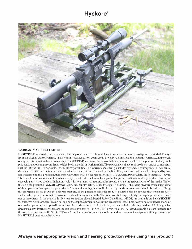
The HYSKORE® Dual Damper Machine Rest is a precision sighting tool that will provide maximum repeatability. Over 80% of all center fire rifle shots made in the U.S. are made from guns in the .30 caliber range on down, therefore, this rest is designed to progressively absorb the recoil pulse from 5.56 / .223 up to and including .300 Winchester Magnum and .338 Winchester Magnum cartridges. The rest features surgically precise and user friendly windage and elevation controls.
Always wear appropriate vision and hearing protection when using this product!
Page 2
IntroductionIf you step back and take a look at the center fire rifles that are actually shot in this country you would find that 80% or more of the shots made are from rifles in the range of .223 /.5.56 up to and including the .300 Winchester and the .338 Winchester Magnums. Guns larger than that are much more expensive to shoot and generally speaking have recoil that discourages repetitive shooting. With that thought in mind we designed the dual damper rest to be able to progressively absorb the recoil pulse on the above mentioned guns. The objective of this rest is to provide absolute maximum repeatability from shot to shot. This means that once a gun is properly mounted in the rest and the rest is properly secured to a table or platform that does not move it will repeat shot after shot whatever the gun and ammo combination is capable of producing. If the rest is mounted, as previously mentioned, and you have a 1 M.O.A. gun / ammo combo the rest will repeat at 1 M.O.A. If you have a 3 M.O.A. combo expect the rest to repeat at 3 M.O.A. The rest will not make a 3 M.O.A. gun produce results at 1 M.O.A. – Sorry!
In order to achieve this degree of repeatability precision engineering and components were required. There are two N20 compression dampers that progressively absorb the recoil pulse and return the gun to battery. The compression dampers are fixed to the lower frame in the gun carrier assembly. The lower frame incorporates two longitudinal chrome plated shafts and the gun carrier assembly has four precision linear bearings that ride along these shafts. The windage adjustment, which can be operated from either the left or right side, uses the same technology. There are two linear bearings that ride on two chrome plated shafts to ensure a precise and smooth adjustment. The elevation can be operated by either hand via a capstan style knob which moves the forward gun support up or down and this assembly can be locked in place with a T handled bolt. In addition, in order to remove any possibility of shooter induced motion contamination the set is equipped with a remote hydraulic trigger release. Although the rest is primarily designed for a hands free calibration of gun, sight, and ammunition, the rear vise assembly can be removed exposing a platform for a rest bag for use at the range. The rest is designed to remove the variables for sighting calibration. If, at the end of the day, with the gun out of the rest, the results are not the same as the results with the gun in the rest the focus needs to move to operator error.
Always wear appropriate vision and hearing protection when using this product!If you do something dumb, bad things can happen.

Page 3
Using the 2 small knobs mount the vise assembly to the rear of the rest as shown. (Vise half forward and the strap retainers to the rear.)
Install the strap over the 2 strap retainer ears.
1
Install the V-notch. Make sure the flat side of the shaft is facing the screw hole for the T bolt.
2
Install the T bolt. The end of the T bolt rides against the flat part of the shaft on the V notch. If you loosen the T bolt too much the shaft will rotate, if you tighten the T bolt so it’s making firm contact with the flat side of the shaft and then back it off 1⁄8 of a turn you will be able to operate the capstan knob and this will move the V notch up and down. When you are at your preferred elevation tighten the T bolt and the elevation will remain fixed.
Install the bench grip arms. Simply extend the arms over the end of the bench insert them into the tubes as shown, and secure with the supplied bolts and wing nuts. It is important that these arms firmly grip the forward edge of the bench so that the rest does not move.
3 4
Assembly
Always wear appropriate vision and hearing protection when using this product!
Page 4
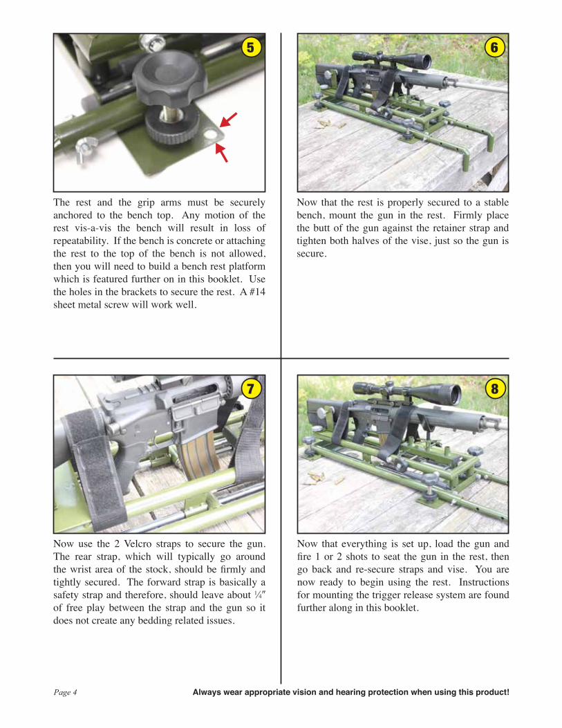
The rest and the grip arms must be securely anchored to the bench top. Any motion of the rest vis-a-vis the bench will result in loss of repeatability. If the bench is concrete or attaching the rest to the top of the bench is not allowed, then you will need to build a bench rest platform which is featured further on in this booklet. Use the holes in the brackets to secure the rest. A #14 sheet metal screw will work well.
5 6
Now that the rest is properly secured to a stable bench, mount the gun in the rest. Firmly place the butt of the gun against the retainer strap and tighten both halves of the vise, just so the gun is secure.
Now use the 2 Velcro straps to secure the gun. The rear strap, which will typically go around the wrist area of the stock, should be firmly and tightly secured. The forward strap is basically a safety strap and therefore, should leave about 1⁄4 of free play between the strap and the gun so it does not create any bedding related issues.
7
Now that everything is set up, load the gun and fire 1 or 2 shots to seat the gun in the rest, then go back and re-secure straps and vise. You are now ready to begin using the rest. Instructions for mounting the trigger release system are found further along in this booklet.
8
▲
▲
Always wear appropriate vision and hearing protection when using this product!

Page 5
The forward gun support can be located at any of 3 locations to accommodate various gun lengths.
9 10
Windage can be adjusted from either side. If there is slack in the screw drive back off the hex nut retaining the knob on one side. Hold the knob on the other side then tighten the knob until contact is made. Now back off slightly and re-fix the hex nut. You may have to repeat until you get it exactly right.
Removing the vise exposes a platform suitable for a rest bag.
11
Protective rubber caps prevent damage to delicate surfaces.
12
▲ ▲
Always wear appropriate vision and hearing protection when using this product!

Page 6
How To…Attach the Hydraulic Trigger Release
Note that the threaded bolt that attaches to the half of the clamp that
moves passes through the trigger guard (Not under or ahead of it)
forward of the trigger. Attached to an AR - 15
▲
▲
▲▲
▲
1 Meter Tube
Plunger Trigger Activator
Clamp
Master Cylinder
The red fluid is for illustration purposes only.
Always wear appropriate vision and hearing protection when using this product!

Page 7
In some cases the clamp must be disassembled to
be properly fitted.
If the slave cylinder fits too close to the for-end it may be necessary to make a shim (1⁄4 plywood would work well) and place it between the clamp and the trigger guard.
Attached to an AR - 15
Attached to a Model 70
Always wear appropriate vision and hearing protection when using this product!

Page 8
All of the above captioned rifle rests must be secured to a bench. When there is a concrete bench or a range that doesn’t allow shooters to screw anything to their benches it is necessary to mount your rest to a platform that can be fixed to the bench using “C” Clamps.30013 is illustrated. Different models may require a larger notch.
Hyskore®
Suggestions For Building AShooting Bench Platform
For the 30013 Dangerous Game® Rest30088 DLX Precision Rifle Rest30185 Black Gun® Machine Rest
30275 Dual Damper Precision Machine Rest
▲
Always wear appropriate vision and hearing protection when using this product!

Page 9
Using a 24 x 24 x 3⁄4 piece of plywood cut a 6 x 24
section of the plywood for the front edge brace.
Cut 2 - 10 pieces of 2 x 4. Glue and screw them to
the plywood base.
A B
Suggested Bill of Materials:For Constructing a Bench Platform
These components can be purchased at any big box home improvement retailer.
Qty. Description1 - 24 x 48 x 3⁄4 Plywood
2 - 2 x 4 x 8 wood block
2 - 6 or 8 stair angles (These are heavy duty 90° angle braces. At Lowes or Home Depot they can be found in the lumber area with the joist hangers.)
1 - Wood Glue (The exterior type is the best)
2 - 5⁄16 x 3⁄4 Sheet Metal Screws
1 - 5⁄16 x 11⁄2 (or 2) Sheet Metal Screw
16-20 - 2 Drywall Screws
2 or 4 - “C” Clamps (size will depend on the thickness of the bench)
Always wear appropriate vision and hearing protection when using this product!

Glue and screw (with 2 screws) the 6 x 24 piece of plywood across the front as shown.
Use 2 x 6 (or 8) stair angles for reinforcement.Secure with screws.
D
Use 2 screws to secure the2 x 4 x 10 blocks from
the underside.
C
Page 10
Use 1 - 5⁄16 x 1 1⁄2 (or 2) sheet metal screw to anchor
the bench grip arms.
G
Use 2 or 4 - “C” clamps to anchor the completed set-up to the bench.
H
Use 2 - 5⁄16 X 3⁄4 sheet metal screws to anchor the left & right sides of the rest.
You may find it necessary to stack several flat washers between the flange on
the rest and the plywood.
F
Before cutting the notch examine your rest. Different models require different size notch(es).
Notch the front so that the edge of the notch is flush with the surface of the plywood base.
This can be done either before or after it is fixed in place.
E
Always wear appropriate vision and hearing protection when using this product!

• REPLACEMENT PARTS •
Visit our website: www.hyskore.com
These are replacement parts for purchase. Pictures do not represent contents of set.
Parts List:30275 - 1 Gun Vise ................................................................................. $ 37.5030275 - 2 Vise Hold Down Knobs ........................................................... $ 17.5030275 - 3 V Notch ................................................................................... $ 12.0030275 - 4 Elevation Capstan ................................................................... $ 10.0030271 - 3 Protective Leveler Caps (4 pcs.) ............................................. $ 05.0030275 - 5 Elevation T Bolt ....................................................................... $ 07.5030105 - 9 Butt Retention Strap................................................................ $ 10.5030088 - 11 Velcro Straps........................................................................... $ 15.0030272 - 3 Leveling Jack & Knob ............................................................. $ 17.5030275 - 6 N20 Damper............................................................................ $ 37.5030275 - 7 Bench Grip Arm....................................................................... $ 15.0030088 - 14 Hydraulic Trigger Release....................................................... $ 22.50
Send Check or Money Order with Phone Number to:Power Aisle, Inc.P.O. Box 983Middleburgh, NY 12122NYS Resident add 8.75% Sales Tax
** $10.00 Shipping & Handling to Lower 48 States**
** $25.00 Shipping & Handling to Alaska, Hawaii, Puerto Rico**
30271 - 3
30272 - 3
30275 - 4
30105 - 9
30275 - 7
30275 - 5
30275 - 6
30275 - 1 30275 - 2 30275 - 3
30088 - 11
30088 - 14
Always wear appropriate vision and hearing protection when using this product!
Hyskore®
Always wear appropriate vision and hearing protection when using this product!
WARRANTY AND DISCLAIMERSHYSKORE®/Power Aisle, Inc. guarantees that its products are free from defects in material and workmanship for a period of 90 days from the original date of purchase. This Warranty applies to non-commercial use only. Commercial use voids this warranty. In the event of any defects in material or workmanship, HYSKORE®/Power Aisle, Inc.’s sole liability therefore shall be the replacement of any such product(s) and/or components that are defective in material or workmanship. The replacement of any such product(s) and/or components shall be HYSKORE®/Power Aisle, Inc.’s sole responsibility. This warranty specifically excludes any and all consequential or accidental damages. No other warranties or liabilities whatsoever are either expressed or implied. If any such warranties shall be imposed by law, not withstanding this provision, then such warranties shall be the responsibility of HYSKORE®/Power Aisle, Inc.’s immediate buyer. There shall be no warranties of merchantability, use of trade, or fitness for a particular purpose. Alteration of any product, misuse, or exceeding any stated product limitations voids this warranty. All returns, adjustments, etc. are the responsibility of the retailer/dealer that sold the product. HYSKORE®/Power Aisle, Inc. handles return issues through it’s dealers. It should be obvious when using some of these products that approved protective safety gear, including, but not limited to, eye and ear protection, should be utilized. Using the appropriate safety gear is the sole responsibility of the person(s) using the product. It should also be obvious that certain products such as silica gel, etc. must not be consumed, inhaled or taken internally. The user takes full responsibility for inappropriate or incorrect use of these items. In the event an inadvertent event takes place, Material Safety Data Sheets (MSDS) are available on the HYSKORE® website. www.hyskore.com. We do not sell guns, scopes, ammunition, cleaning accessories, etc. These accessories are used in many of our product pictures, as props to illustrate how the products are used. As such, they are not included with any product. All photographs, drawings, copy, instructions, etc. are the exclusive property of HYSKORE®/Power Aisle, Inc. All downloadable files are intended for the use of the end user of HYSKORE®/Power Aisle, Inc.’s products and cannot be reproduced without the express written permission of HYSKORE®/Power Aisle, Inc. ©2015