· (2v / div) (5a / div) 10a/us voltage ... measurement terminal voltage / average current /...
TRANSCRIPT

Short formCatalog 2016KG Products for Application
Electronic LoadP.6
http://www.keisoku.co.jp/en/
Lively KG!
Ripple & Noise MeterP.10
Regenerative DC E-LoadLED Emulator / Battery TesterP.12
Power Supply A.T.E.P.16
Simulation SoftwareP.18
AC/DC regenerative Electronic LoadP.4
Bidirectional PowersupplydP.4
KEISOKU GIKEN Co., Ltd.2-12-2, Chigasaki-minami, Tsuzuki-ku, Yokohama 224-0037
JapanTEL : +81-45-948-0211 / FAX : +81-45-948-0221
E-mail : [email protected] : http://www.keisoku.co.jp/en/
http://www.keisoku.co.jp/en/
* Specifications are subject to change without notice. * All trademarks are property of their respective owners.
CP-0091-1502

2 3http://www.keisoku.co.jp/en/ TEL : +81-45-948-0277
Electronic Load
Ripple & Noise Meter
Auto Test Equipment fot SMPS
High Speed Circuit Simulator
Unique Technology
Index
Option & Accessories
Battery Tester & Emulator
Application / Corporate Profile
LED Emulator
Bidirectional PowersupplyNT Series (Bidirectional powersupply) ………………………… 4
Ene-phant Series (AC/DC Regenerative Electronic Load) …… 4
Load Station Series (Multi-purpose Electronic Load) ………… 6
E-Load Player (Utility software for Electronic load) …………… 6
Load Star Series (Ultra Fast Electronic Load) ………………… 6
RC-02A (Ripple & Noise measuring option) …………………… 8
Low-L cable ……………………………………………………… 8
UV-11 (USB / GP-IB converter) ………………………………… 8
DP-100 (Differential probe) …………………………………… 8
TRC-50F2 (HF-terminator) ……………………………………… 8
RM-103 (Ripple & Noise meter) ………………………………… 10
SC-82 (Ripple & Noise scanner) ………………………………… 10
LE-Series (LED Emulator) ………………………………………… 12
MCD Series (Multi-channel charge / discharge tester) ……… 14
PW-600E (Power supply auto-inspection system) …………… 16
PowerTestSite (Auto-inspection software for PW-600E) …… 16
PowerTestSIte MINI (Auto inspection software) ……………… 16
SCAT (High Speed Circuite Simulator) ………………………… 18
Unique technilogy (E-Load, Ripple & Noise measurement) … 19
Application Overview …………………………………………… 23
KG Web Site ……………………………………………………… 31
News Letter ……………………………………………………… 32
Application Notes………………………………………………… 33
Corporate Profile ………………………………………………… 34
PW-600E has been discontinued for its production.When necessary, please contact us for the availability from our stock.We will quote to customers PTS-mini instead of PW-600E once all stock is sold out.Please contact our sales department for detail.
4 5http://www.keisoku.co.jp/en/ TEL : +81-45-948-0277
ElectronicLoadAC/DC E-Load
Bidirectional Powersupply
AC/DC Regenerative Electronic LoadEne-phant Series
Loading power Max voltage Max current Mode
NT-AA-10KE-L 10kW AC480VrmsDC680V
60Arms60A
AC:CC/CR/CPDC:CC/CR/CV/CP
PF/CF(AC)MPPT(DC)
Interface General:USB, RS-232C, LAN(Ethernet) Option:GP-IB
● Various AC Loading Tests For Inverters and Power Generators ● Loading test for High Voltage DC Power Supplies or Converters ● Conforming to the Grid-interconnection Code ● Adapted to 8 different capacities and input types with its Master-Slave operation
USBUSB
DC680V
AC & DC Dual Purposes + Regenerative Operation !
AC480V
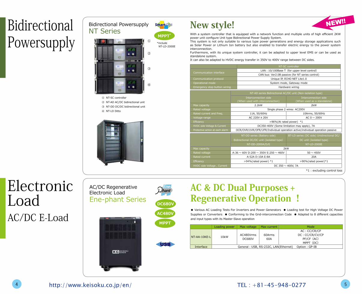
Bidirectional PowersupplyNT Series With a system controller that is equipped with a network function and multiple units of high efficient 2KW
power unit configure Unit type Bidirectional Power Supply System.This system is not only suitable to various type power generations and energy storage applications such as Solar Power or Lithium Ion battery but also enabled to transfer electric energy to the power system interconnection.Furthermore, with its unique system controller, it can be adapted to upper level EMS or can be used as standalone system.It can also be adapted to HVDC energy transfer in 350V to 400V range between DC sides.
New style!
NT-SC controller
Communication interfaceLAN:10/100Base T(for upper level control)
CAN bus: Ver2.0B passive (for NT series control)Communication protocol Unique IP, ECHO NET Lite1.0Operational mode System mode, Gateway modeEmergency stop button wiring Hardware wiring
NT-AD series Bidirectional AC/DC unit (Non-isolation type)Interconnection side
(When used with interconnection)Interconnection side
(When used as a standalone)Max capacity 2.2kW 2kWRated voltage Single phase 2 wires: AC200VRated current and Freq. 11A, 50/60Hz 10Arms, 50/60HzVoltage range AC 220V ± 20V AC 0 ~ 200VEfficiency >96%(At rated power) *1HVDC side Voltage & Current DC350-400V (Some limitation may apply), 7AProtective action at each alarm OCR/OVR/UVR/OFR/UFR/Individual operation active/individual operation passive
NT-DD series (Battery side)Bidirectional DC/DC unit (Isolated type)
BT-LD series (DC side) Unidirectional DC/DC unit (Isolated type)
NT-DD-2000A/D/E NT-LD-2000EMax capacity 2kWRated voltage A:36 ~ 60V D:200 ~ 350V E:250 ~ 460V 50 ~ 450VRated current A:52A D:10A E:8A 20AEfficiency >94%(rated power) *1 >90%(rated power)*1HVDC side Voltage , Current DC 350 ~ 400V, 7A
*1 : excluding control loss
NEW!!
①
②
③
④
① NT-SC controller② NT-AD AC/DC bidirectional unit③ NT-DD DC/DC bidirectional unit④ NT-LD Ditto
MPPT*
Smart GridSmart Grid
*include NT-LD-2000E
MPPT

Need just Electronic load, PC and GPIB interface.
E-Load Player Compatible model
Electronic load
LN-300A/LN-300CLN-1000A/LN-1000C
ELA-155/ELB-155/ELC-155ELA-305/ELB-305/ELC-305
ELA-1005/ELC-1005/ELZ-175ELL-355/ELL-1005
GP-IB interface GPIB-USB-HS(NI)PCI-GPIB(NI)
● 6 different software such as I-V are bundled ● Various data can be stored or read ● Easy operation in graphical manner ● Open source code for customization ● Shorten the development cost of Automatic Test Software
Utility software for Electronic loadE-Load Player
E-Load Player recommended environmentOS Windows Vista / 7 (32bit)CPU Pentium4 or betterMemory 1GB or overHDD 100MB or overMonitor 1280 × 1024 dots
Free!
Ultra Fast Electronic LoadELS-304
Voltage Current Power Slew rateRating 30V 120A 300W 200A/usRise / Fall time 100nsLoading mode CC, CR, CV, CP, Dynamic, Ext-Cont., ShortInterface GP-IB / USB / Ext-Cont. (Ai)Option (RC-02A) Ripple & Noise measurement
● Realized Ultra Fast Adjustable 200A/us Slew Rate ● No Minimum Operating Voltage as It Sinks at about 0V ● Fast Operation in Nanosecond Order ● Wideband of 100kHz ● Reduced impedance by new CKT (Pat) ● Suitable for Impedance Measurement of Devices like POL,VRM and Capacitors
Ultra Fast 200A/us !
200A/us
USBUSB
6 7http://www.keisoku.co.jp/en/ TEL : +81-45-948-0277
ElectronicLoadDC E-Load
Multi-Purpose Electronic LoadLoad Station Series
Load Station Series Voltage Current Power Slew rateLN-300A-G7 120V 60A 300W 20A/usLN-1000A-G7 120V 180A 1000W 30A/usLN-300C-G7 500V 12A 300W 1A/usLN-1000C-G7 500V 36A 1000W 3A/usRise / Fall time 500nsLoading mode CC, CR, CV, CP, Dynamic, Ext-Cont., ShortInterface GP-IB, USB, Ext-Cont. (Ai), BoosterI/OOption (RC-02A) Ripple & Noise measurement
● 4 models in 300W and 1000W ● High speed loading yet providing no overshoot ● No minimum operating voltage as it sinks at about 0V ● Fast slew rate and 100kHz wideband operation● Booster function up to 10 units parallel ● Adapted to LabVIEW driver ● Optional Ripple & Noise measurement ● Suitable to Power, Battery, and Device development as well as inspections
No Overshoot!USBUSB
NEW!!
NEW!!

Ripple & Noise measurement optionRC-02A
DCV measurementMeasurement range ± 6.0000V ± 60.000V ± 500.00VResolution 0.1mV 1mV 10mV
Ripple & Noise measurement ModelsMeasurement range 300mV 3000mV
LN-300A/LN-1000ALN-300C/LN-1000C
ELL-355/1005ELZ-175ELS-304
Resolution 0.1mV 1mV Input Resistance 1M Ω for DC, 50 Ω for HFNominal Bandwidth 100MHz (3dB)L.F. filter 50Hz ~ 2kHz H.F. filter 50Hz / 5kHz Bandwidth Limit filter 20MHzRipple separation ratio 0.5% ~ 50.0%(Resolution:0.5%)
● Ripple & Noise measurement option can be incorporated ● Option board on its back panel ● DC 0.1mV resolution measurement possible ● Factory options ● Suitable for SMPS test
Low-L cable
Length Withstanding voltage Rated current Resistance (DC) Inductance
LL-050 50cm500V
100A 1m Ω 80nHLL-100 100cm 60A 2m Ω 100nHLL-200 200cm 40A 4m Ω 130nH
● Specially designed high current low inductance cable
● Inductance reduced to 1/3 compared to twisted cables
● Suitable for fast transient testing
Reduced Inductance !
General cable Low-L cable
Load voltage(2V / div)
Load current(5A / div)10A/us
Voltagedrop
Voltagedrop
Ripple & Noise Measurement on Electronic Load !
RC-02A
USB to GP-IB converterUV-11
Interface USB Rev 1.0 / ANSI-IEEE488.1Environment IBM PC-AT or equivalent, USB interface / Microsoft WindowsXP(Japanese version)
● USB to GP-IB converter ● Hot-plug ● 10 max to 1 PC ● Windows COM components such as Excel is used ● Best suitable for ATE application
GP-IB control through USB !
USBUSB
Differential probeDP-100 ● The common mode noise can be eliminated that causes reading error on measuring ripple & noise ● It
can be used with oscilloscope and Ripple & noise meter
Eliminating common mode noise!
Max input voltage ± 200V(DC or ACp-p) Freq. bandwidth / Impedance DC ~ 100MHz / 50 Ω(> 1MHz)
CMRR / Dividing ratio 40dB(100MHz) / 1:1
HF terminatorTRC-50F2
● Characteristic impedance of 50 Ω ● Incorporated Capacitor cuts DC component ● Best with oscilloscope to measure ripple & noise
Best for measuring power supply output!
Max input voltage / Impedance DC500V / 50 Ω , 0.01 μ F Freq. bandwidth / Continuous power 1MHz ~ 100MHz / 0.25W
8 9http://www.keisoku.co.jp/en/ TEL : +81-45-948-0277
OptionAccessories

Ripple & Noise meterRM-103
DC measurementRange ± 6.0000V ± 60.000V ± 500.00VResolution 0.1mV 1mV 10mV
Ripple & noise Measurement
Range 300.0mVp-p 3000mVp-pResolution 0.1mV 1mVBandwidth 100MHzFilter(LF, HF, THRU) 50Hz ~ 2kHz, 2kHz ~ , 50Hz ~ 100MHzBW limit filter 20MHz
Input impedance DCV, Ripple DC 1M Ω , HF50 Ω
InterfaceGP-IB IEEE488.1I / O Start input, Go-No Go output, SC-82 control output
● One touch ripple & noise measurement ● No reading error by digital reading ● Conforming to JEITA(*)● Only one digital ripple & noise meter ● Discriminating Ripple and Noise by pulse width duty ratio method● Auto ripple discrimination ratio setting ● PASS/FAIL judgment ● Standard GP-IB interface ● Best for power supply inspection and maintenance
* Japan Electronics and Information Technology Industries Association.
One touch digital reading !
Ripple & Noise scannerSC-82
No. of channel / Freq. BW 8 ch / DC ~ 100MHz (-4dB)Switchable voltage / Sequence DC300Vmax / Break Before MakeSwitching mode Panel switch or external signal (TTL)
● 8ch input(Isolated each other) ● Max 16 possible by connecting 2 ● Freq. BW of 100MHz ● Remote control possible from RM-103 ● Suitable for multi-channel power supply test
Automated ripple & noise measurement !
8ch
10 11http://www.keisoku.co.jp/en/ TEL : +81-45-948-0277
Ripple &Noise Meter,Scanner

LED EmulatorLE Series Electronic
load
LE-5150-01 LE-5150-02No. of channel 1 2Rated voltage 500V 500VRated current 3A 3ARated power 150W 150WLoad mode CV + CR、 Real LEDMeasurement Terminal voltage / Average current / Ripple current / Load current duty ratioOther feature Pulse output for PWM dimming test (4ch)Interface USBExpansion ― ―Height 1U
● For low power back light to high current illumination application ● Evaluate LED PS or drivers Quantitatively ● Real LED mode to simulate precisely the LED(LE-5000 series) ● High speed response over 100kHz enables to test PWM dimming driver ● Incorporated pulse output for PWM dimming driver testing ● Dedicated measuring software
1U1Urevolution!revolution!
USBUSB
LED not dazzling !
For Power LED lamp driver!
LE-5150-02 500V, 3A, 2ch × 150W
6A
3A
200mA300mA600mA
LED sign
LED lighting
LED back light
Current
Voltage300V50V 500V
LE-5150-02 (300W)(*when in parallel)
LE-5150-01 (150W)
LE-3060 (60W)
3 models cover from low power to high power applications.
* Parallel connection: Inner units of LE-5150 only.
Real LEDmode
Load curve
CV+CR mode
It realized LED characteristics by usingexponential curve for better reproductionof LED characteristics.
NEW
Full coverage of low to high power
Real LED mode! (LE-5150 series)
Both the setting and measurement are on the same screen.
The loading characteristics can be set visually through GUI.
INOUT
Load input
LED driver
Pulse outputLE-3060 : 8chLE-5150 : 4ch
SMPS
CV output Ordinary Load
LED driver
CC output LED emulator
CC mode : Fast
CV mode : Slow
CV mode : Fast+
CR operation
> 100kHz
Dedicated software (Incorporated with the emulator) for ease of use
Incorporated pulse output for PWM dimmer
What is different between Electronic load and LED emulator?Ordinary electronic load are designed to be used for constant voltage sources thus the response of CC mode is fast but slow in CV mode. As contrary, the output of LED drivers is in CC mode thus high speed CV operation and CR mode are necessary. The LED emulator realized such characteristics intended to test LED derivers.
12 13http://www.keisoku.co.jp/en/ TEL : +81-45-948-0277
LED Emulator
NEW!!

Multi-channel charge / discharge testerMCD Series ● 5ch electronic loads in 1U(approx.43mm) ● Incorporated isolated 5ch power supplies ● Suitable to low
capacity multichannel charge/discharge tester ● Can be used for ECU test while simulating battery cell ● High precision and high speed, isolated channel configuration ● High speed sequence operation by hardware ● Best for HILS and ECU test ● Good for separator and coin cell battery test
One for two !1U1Urevolution!revolution!
5chUSBUSB
Coin cell secondary battery
As a charger / discharger
Coin cell batteries or separators and other materials for batteries.
5V, 200mA × 5ch
… ………
Battery ECU Battery
Real WorldReal World Virtual World (Real time simulation)Virtual World (Real time simulation)
Virtual World(Local simulation)Virtual World(Local simulation)
Dedicated Software
Power management ECU
Battery monitor ECU
5V, 200mA×5ch5V, 200mA×5ch
MCD-05-05002
Power management ECU
Battery monitor ECU
MCD-05-05002
USB
LAN
or C
AN
5V, 200mA×5ch5V, 200mA×5ch
Battery HILSBattery HILS
Hardware synchronization up to 50ch.
High speed controller
Hardware synchronization up to 100ch.
As a Battery Emulator
Open circuit detection possible by connecting in series.
MCD-05-05002
MCD-05-05002 MCD-05-05005 MCD-05-05010No. of channel 5V / 200mA × 5ch 5V / 500mA × 5ch 5V / 1A × 5ch
Charge
Charge mode CC, CV (automatic crossover)Voltage range 5V ~ 0V (single range)
Current range200mA ~ 0mA(single range)
500mA ~ 0mA(single range)
1000mA ~ 0mA(single range)
DischargeDischarge mode CC, CV (automatic crossover)
Current range0 ~ -200mA(single range)
0 ~ -500mA(single range)
0 ~ -1000mA(single range)
Measurement
Measuring mode DUT voltage, charge current, discharge current, static capacity, battery capacity, internal R
DCV range 6V ~ 0V (single range)
DCA range220mA ~ -220mA
(single range)550mA ~ -550mA
(single range)1100mA ~ -1100mA
(single range)Time resolution 3ms (hardware)
InterfaceUSB USB1.1I/O 8ch photo coupler isolated open collector output (12V/10mA, max24V/10mA)
14 15http://www.keisoku.co.jp/en/ TEL : +81-45-948-0277
Battery Tester &Emulator
NEW!!

Power supply auto-inspection systemPW-600E ● All-in-one test system with 5ch loads ● Dedication to ATE enables high speed inspection ● Expandable to
max 20 channels ● PowerTestSite dedicated software for PW-600E ● Dual AD converters for simultaneous V & A measurement ● Accurate power measurement ● Optional stand-by current measurement
Testing SoftwareTesting Software
Auto-inspection softwarePowerTestSite MINI
● This is better when smaller inspection system than PW-600E is needed at lower cost ● The software operation is compatible to PowerTestSite ● Ready-made test items make easier to program
System Model DetailPW-600E for AC / DC
convertermodel-602A 2kVA AC PS (PWM-Linear combined model)
model-600E (*) 5-ch Power supply Tester
PW-600E for DC/DC converter
model-519/5A DC source controller* Model number differs according to the rated current
* External DC PS is needed separately
model-519/10Amodel-519/20Amodel-519/50Amodel-600E(*) 5-ch Power Supply Tester
*) There are different types on model-600E as RC01/RC03 in accordance to the measurement method .
For Turnkey Project!
M I N ITesting SoftwareTesting Software
for AC / DC converterPW-600E test system
Best for small sized test system !
USBUSB
For AC / DC converter inspection
model-602A
model-600E
D.U.T.(AC / DC converter)
IN
OUT
For DC / DC converter inspectionmodel-600ED.U.T.
(DC / DC converter)
IN OUTmodel-519
DC PS
Auto-inspection software for PW-600EPowerTestSite
IN OUT
UV-11
AC P/S
E-Load
D.U.T.(AC / DC converter)
GP-IB
PowerTestSiteMINI system
USB
* Max. 5 GP-IB devices、 max. 4 loadings
16 17http://www.keisoku.co.jp/en/ TEL : +81-45-948-0277
Auto Test Equipmentfor SMPS

Version K.492
● Hundreds to several thousand times faster than general purpose circuit simulator ● Stable operation in large scaled circuit simulation ● Adapted to DSP ● Academic license for unlimited users available
Adapted DSP! English Version!
model detailSCAT 1 user license
SCAT/10 10 users licenseSCAT/Net10 10 users network license
SCAT/A Academic license (1 user)SCAT/AS-F Unlimited user license for Academic Network license
SCAT recommended environmentOS WindowsXP / Vista / 7CPU > Pentium 2GHzRAM > 2GBInterface USB(Mandatory)Monitor 1280 × 1024 dot
The SCAT(Switching Converter Analysis Tool)was developed in Energy Electronics Laboratory of SOJO university as high speed circuit simulator by Prof. Nakahara dedicated to simulate switching power supply.
DSP block
Ripple & noise waveform
SMPS
The output of SMPS contains both ripple and noise. Oscillo-scope can be used to observe both of them but they are mixed and can not be sepa-rated.
A B
CDE
Ripple & noise waveform of SMPS
Pulse width ofswitching noise(Tn)
Switching ripplevoltage
Switching period
(Ts)
AC line frequency(50 / 60Hz)
The switching ripple is easily separated by using the ratio of Tn and Ts.
dodifferently!
SMPS
Multi-Purpose E- loadLN-300A-G6
Rear panel
A Ripple & noise B Ripple C Noise
D Switching ripple E AC ripple
LN and ELx series electronic load can incorporate optional ripple & noise measurement module (RC-02A).
dodifferently!
Output
18 19http://www.keisoku.co.jp/en/ TEL : +81-45-948-0277
High Speed Circuit SimulatorRipple discrimination technology
(Pulse width duty ratio comparison method)
Ripple & noise measurement on electronic load
Unique technology from KG
NEW!!

… Ordinary E-Load … Our E-Load
Below minoperating voltage
Ordinary E-Load
Current
Voltage
Typical load
It limits the loading current below minimum operating voltage as to protect it from rush current.
KG E-Load
Current
Voltage
It start loading from 0V like a resistor and works proportion-ally to its input voltage.
Our Electronic load
Delay
1.5V(min operating voltage)
0V Turn the load on at this point
Turn on output of DUT
Time
Current Voltage
Current Waveform
Voltage Waveform
Soft Start method
It has a delay on the load-ing current until the voltage reaches to the minimum op-erating voltage. This delay causes some problems when evaluating power supplies
KG E-Load
Current
Voltage
As there is no time delay on the current, this can evaluate more accurately the charac-teristics of power supplies at low voltage region.
No time delay
KG E-Load
Current
Voltage
As there is no bias source, there is no additional factors to consider about.
Less bias source method
70
60
50
40
30
20
10
0 0 1 2 3 4
Low voltage region
Loading terminal voltage
70
60
50
40
30
20
10
0 0 1 2 3 4
Loading terminal voltage
-1.5V(bias voltage)
DUT voltage
Turn on output of DUT Time
Current Voltage
Current Waveform
Voltage Waveform
Bias source method
Due to additional bias power source, there will be some effect of additional noise or reverse current.
Low voltage region
Great difference can be seen in a graph.
Current
Voltage
There will be a large amount of rush current when turned on the E-load while DC source has been supplied.
The smooth transition is obtained by KG’ s unique high speed current control technology.
Overshot when in CC mode at the rising edge.
Ideal current curve without over-shoot.
Rush current
Overshoot
Ringing
Smooth transition
Smooth transition
No ringing
200A/μs100A/μs
50A/μs20A/μs
12A/DIV 500ns/DIV
KG’ s patented ultra fast response technology benefitted to realize the following features into electronic load such as high speed current control, low voltage operation, wide frequency bandwidth operation and maximum of 500A/us slew rate.
dodifferently!
Curr
ent
Curr
ent
At the dynamic loading. Ideal current curve without overshoot.
20 21http://www.keisoku.co.jp/en/ TEL : +81-45-948-0277
Low Voltage Operation Technology High Speed Current Control Technology
Ultra Fast Response Technology!
Unique technology from KG
電圧
電流
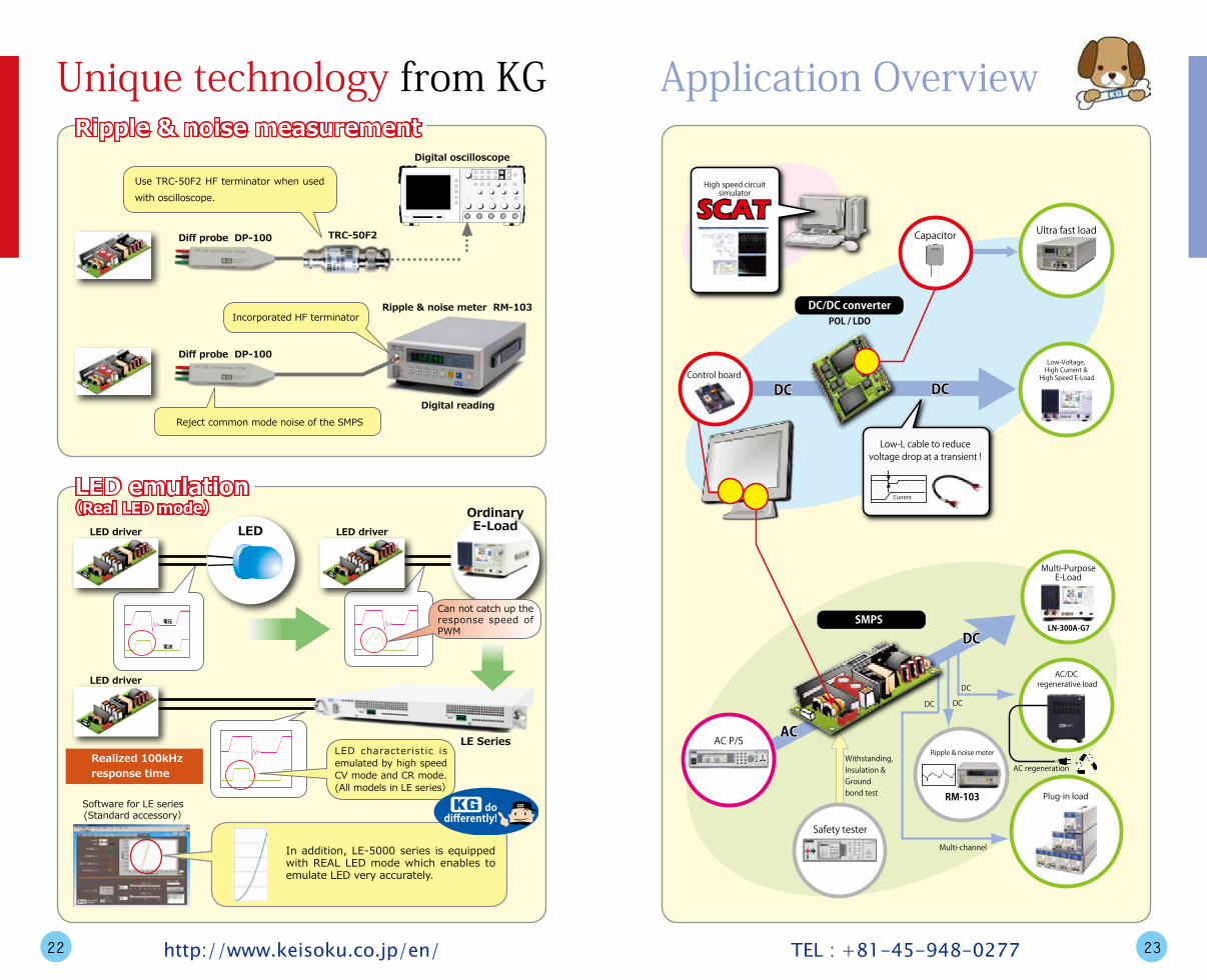
LED driver LEDOrdinaryE-Load
Can not catch up the response speed of PWM
LED driver
LED driver
LED characteristic is emulated by high speed CV mode and CR mode. (All models in LE series)
Software for LE series(Standard accessory)
In addition, LE-5000 series is equipped with REAL LED mode which enables to emulate LED very accurately.
dodifferently!
Realized 100kHz response time
Diff probe DP-100 TRC-50F2
Digital oscilloscope
Use TRC-50F2 HF terminator when used with oscilloscope.
Diff probe DP-100
Ripple & noise meter RM-103
Digital reading
Incorporated HF terminator
Reject common mode noise of the SMPS
AC P/S
Safety tester
Withstanding,Insulation &Groundbond test
Multi-channel
DC
DC
DCDC
ACAC
Plug-in load
AC/DC regenerative load
Ripple & noise meter
RM-103
Low-Voltage, High Current &
High Speed E-Load
Ultra fast load
AC regeneration
SMPS
Control board
DC/DC converterPOL / LDO
DCDC DCDC
Current
Low-L cable to reducevoltage drop at a transient !
Capacitor
High speed circuitsimulator
SCATSCAT
DC
Multi-PurposeE-Load
LN-300A-G7
LE Series
22 23http://www.keisoku.co.jp/en/ TEL : +81-45-948-0277
Unique technology from KGRipple & noise measurement
LED emulation(Real LED mode)
Application Overview

AC power supplyMulti-purpose E-LoadLN-300A-G7 / RC-02A
SMPS USB / GP-IB converer
UV-11
GP-IB
USB
PowerTestSiteMINI
Ripple & Noise can be measured (Optional)
PowerTestSite
Multi-output SMPS
・ AC/DC 2kVA AC P/S・ Power meter・ Standby power measure-
ment (Optional)
・ Remote BOX interface・ Digital I/O (8ch each I/O)・ 16 ch scanner for DVM・ 8 ch scanner for OVP test・ 5 ch measurement unit
(DCV, ripple & noise)・ 5 ch loads・ DC source for OVP test
AC power supplymodel-602A
Load/Measurement unit
model-600E
0V PS out(8ch)DVM input(16ch)Digital I/O(8ch each)
Ex slot 1
Ex slot 2
Ex slot 3
CH1CH2CH3CH4CH5
PW-600E alone can per form whole inspection of SMPS. High speed inspection improves the productivity
POL or LDO Low-L cableLL-050
Low–V, high–A & high speedE-Load
ELS-304
Rush current
Ordinary E-LoadLow–V, high–A, high speed
E-Load
It takes time to reach the setting current and rush current was generated.
No overshoot and fast rising edge was obtained.
Quantified evaluation pos-sible by the ideal current waveform.
Fixture (BTO)
24 25http://www.keisoku.co.jp/en/ TEL : +81-45-948-0277
Out going inspection of SMPS - 1(Min. configuration)
Out going inspection of SMPS - 2(Automatic inspection system)
Evaluation test for POL & LDO for FPGAApplication Overview
Wire harness test by high speed Electronic Load
High speed E-LoadELS-304
DC P/SWS series
Reverse connection protector diode
Secondary battery
100kHz operation
Different duty ratio (up to 8) can be mixed.
Period:1us ~ 60sMax Freq.:250kHzMin response:500ns
Pulse charging by high speed electronic load
High speed E-loadELS-304
DC P/SWS series
Oscilloscope
Current ProbeInductance according to distance.
Cable harness
Detect inductance by response of the DUT.
Body

LED driver
AC source 6000 series
LE-5150-02 (500V, 3A, 150W×2ch)
USBCovers low power to high power.
3A×2ch or6A×1ch (*)
(Parallel use)
*No parallel connection among LE series.
500V / 3A
USB
MCD-05-05002
Expandable up to 200 channels
Expansion cable
LED
26 27http://www.keisoku.co.jp/en/ TEL : +81-45-948-0277
LE-5150 series for Lighting applications
Ripple & Noise measurement at Power Supply MaintenanceApplication OverviewLED test by multichannel constant current source
Ripple & Noise meter RM-103
Air craft
Medicalequipment
Industrialequipment
Mobilephonestation
Chemicalplant
Powerplant
Switching power supplies are widely used in various equipment and ex-pected to world properly and reliably. The failure of switching power sup-ply will result serious damage to the whole system . For sever applica-tions, it is recommended to test and measure the Ripple & Noise of such switching power supply periodically . Such as power plant and aircraft maintenance, they are required to replace certain parts such as electro-lytic capacitors periodically before the end of its life time.
Merit ● Easy Digital Reading ● No reading technique like oscilloscope ● Standardize maintenance work flow ● Interface to other equipment for wider application
*1 : RM-103 comes with one DP-100 diff. probe.
Ripple & Noise meter RM-103
For multi channel…
Ripple & Noise scannerSC-82(optional)
When common mode noiseis the issue…
Differential probe*1DP-100
For automation…
PLC…etc
GP-IB
O/P port
Judgement

… ………Cont
rol c
able SMPS
Lithium-ion battery
Master #1
Slave #1
#2
#3
#4
They can be used independently or in parallel in master-slave configuration when needed higher power loading.
Max. 10 units (10kW) can be connected in parallel as far as they are in the same voltage rating.
They can be configured high voltage, high power electronic load for test-ing EV (Electric vehicle)
or
Coin cell secondary battery
Best for testing such as coin cells. Separator and other materials.
MCD-05
… ………
Battery ECU Battery
Real World Virtual World(Real time simulation)
Virtual World(Local simulation)
Dedicated softwareHydrangea
Power management ECU
Battery monitor ECU
Power management ECU
Battery monitor ECU
5V, 200mA×5ch
MCD-05-05002
5V, 200mA×5ch
MCD-05-05002
USB
LAN
or C
AN
I/F BOX
Suitable for battery emulation that simulates battery cell. (Multichannel isolated source) High speed and Highly accurate measurement.
Open circuit detection is possible by connecting in series!
Hardware synchroniza-tion up to 100ch!
5V/500mA and 5V/1A models also available! Max. 200ch!
28 29http://www.keisoku.co.jp/en/ TEL : +81-45-948-0277
Electronic load expansion
Measurement of coin cell (material)
Battery HILS / ECU testApplication Overview

+-
VAC 1
R1 L1
C1
Lr1 Lr2
LpP1
TRG
Voffr
Q
LTH Rif
CifRis
Dq
Cs
Rs
R3Vr
PR1
R4
C2
PC 1
Rf1
AMP
Rf2 Cf1
VPR1 OUT 1
Rvs 1
RVs 2
Vref
Np Ns Co
D
T
RL
800m
-800m
400m
-400m
00 256 512 768 1.02k 1.28k
Insert a shunt resistor
The SCAT can simulate whether if the circuit is conforming to harmonic regulations such as IEC.
Connect E-loadto the SMPS being designed
E-load is in dynamic mode
Dynamic load current
At the real circuit evaluation How to simulate dynamic loading by SCAT?
Connect a resistor tothe SMPS and locatethe programmable device.
The resistance is recalculatedat the end of the analytical period.
Programmable deviceDynamic simulation is possible by writing a program to control the load.
* All parameters can be varied dynamically
PRC1
RL PRC1
40
-40
20
-20
00 10m 20m 30m 40m 50m
CP
CVCC
Simple, easy and flexible to simulate with using the programmable de-vices.
Simulation circuitFull wave rectifier
By simple 5 lines of program, the RL is assigned as constant power load.
We welcome you to our website. As we up-date applications and technical tips daily, please visit us and write us if you have further questions.
http://www.keisoku.co.jp/en/
Products
Partner list
30 31http://www.keisoku.co.jp/en/ TEL : +81-45-948-0277
Harmonic current analysis by SCAT simulator
Dynamic load simulation by SCAT
KGWebsite
Application Overview

Monthly news letter is circulated to our customers and distributors who requested. Please send your request from our website.
http://www.keisoku.co.jp/en/
KEISOKU GIKEN PW Sales Dept.
TOPICS
Ripple & Noise Measurement of Switching Regulator (SMPS)
Nov. 25, 2009
It is needless to mention that almost all of electronic instruments and OA equipment are equipped with switching regulator inside as a power device. The product which runs on AC100V or 200V are incorporated with AC/DC converter and Note-PC so forth which runs on battery are incorporated with DC/DC converter. The DC output of either AC/Dc or DC/DC converter contains certain amount of ripple & noise component on it. To measure this ripple & noise level is one of important factor.
HOT NEWSHOT NEWShttp://www.keisoku.co.jp
KEISOKU GIKEN CO., LTD. PW sales Dept.
2-12-2 Chigasaki-minami,Tsuzuki-ku, Yokohama-city, Japan URL: http://www.keisoku.co.jp/en/ E-Mail: [email protected] Phone: +81-45-948-0211 FAX: +81-45-948-0221
Switching regulator
Ripple & Noise waveform Purpose of ripple & noise measurement The level of ripple & noise is representing one aspect of switching regulator performance and also used to estimate remaining life time of the regulator. From this context, the ripple & noise level is measured in addition to the output volt-age at the maintenance depot. As the ripple & noise level is heavily in relevant to the component such as electrolytic capacitor that has certain life time. Measuring the ripple & noise properly gives good estimation of its life.
How to Measure Ripple & Noise?As it called ripple & noise, it’s a collective various wave-forms so the accurate measurement is somewhat difficult. It can be measured by oscilloscope but it will require high degree of measuring technique as ripple & noise waveforms has to be pulled out from the collective waveform. This will result dependency who is measuring and their experience. With using ripple & noise meter, there is no reading error or no special technique required. The ripple & noise meter pull out the ripple and noise voltage from the collective compli-cated waveform and display it in digital. As for the measurement method of ripple & noise, JEITA (Japan Electronics and Information Technology Industries Association) standardized as RC-9131B.
Ripple & Noise meterRM-103
The differential probe (DP-100A) x 1 comes with standard accessory. With ripple & noise scanner, it can measure 8 to 16 channels suitable for multi-channel automatic meas-urement system.
This news letter is circulated mainly to KEISOKU GIKEN distributors. Should you require no circulation of this service, please contact us.
KEISOKU GIKEN PW Sales Dept.
TOPICS
Precise and High speed Current Waveform Emulation
Dec. 25, 2009
HOT NEWSHOT NEWS http://www.keisoku.co.jp
KEISOKU GIKEN CO., LTD. PW sales Dept.
2-12-2 Chigasaki-minami,Tsuzuki-ku, Yokohama-city, Japan URL: http://www.keisoku.co.jp/en/ E-Mail: [email protected] Phone: +81-45-948-0211 FAX: +81-45-948-0221
This news letter is circulated mainly to KEISOKU GIKEN distributors. Should you require no circulation of this service, please con-tact us.
When in Load Regulation test, normally electronic load is used. But it limits the test within the features equipped in the electronic load. When our Electronic load is used, it can emulate real loading current when connected a function generator to external input of the electronic load. This is extremely suitable to test such as current waveform of motor used in a electronic vehicle.
Please consult us, we produce software to your need on LabVIEW of national Instruments.
Cont. Voltage (0~10V)
Load Current
Function generator
High speed E-Load
USB
Function generator alone may be generated arbitrarily waveform but the software attached to will be more flexi-ble and suitable to generate your waveform.
Powersupply
Function generator alone can generate various waveforms and provided sequence function. With Arbitrarily waveform software, much wider range of flexibility is obtained.
Connect function generator output to EXT. input of elec-tronic load as waveform A and waveform B. The electronic load may be responded in accordance to the output waveform of the function generator. With this function, electronic load can emulate various loading conditions.
A
B
A´
B´
TOPICS
All-in-one Tester for LED driv-ers with PWM dimming function
LED
Driver PWM DIMMING
Expandable to max. 200 channels
PULSE OUT (Max.8 channels )
Expansion cable
Dedicated software
USB
Driver output
It is necessary to test PWM dimmer function when testing LED Driver which is equipped with PWM dimmer features in addition to power source testing. To do that, it is required to apply pulses to the PWM input which is in proportional to the dimmer level. LE-3060 is equipped with standard PWM out-put function that enables LED driver testing simply as seen below. With the dedicated software, load characteristics and various measurement settings are easy.
LE-3060
LE-3060
PW-600E Automatic Power Supply Inspection System can be expanded to test LIPS when used with LE-3060. (LIPS:LCD TV power source)
KEISOKU GIKEN PW Sales Dept.
Apr. 9, 2010 http://www.keisoku.co.jp
KEISOKU GIKEN CO., LTD. PW sales Dept.
2-12-2 Chigasaki-minami, Tsuzuki-ku, Yokohama-city, Japan URL: http://www.keisoku.co.jp/en/ E-Mail: [email protected] Phone: +81-45-948-0211 FAX: +81-45-948-0221
Should you require no circulation of this service, please send E-mail to [email protected].
NEWSLETTERNEWSLETTER
TOPICS
Best solution for Battery ECU Testing
The Electronic Control Unit (ECU) is widely used in vehicles including EV (Electric Vehicle) and HEV (Hybrid Electric Vehicle). The Battery ECU is built intended to monitor each battery cell hence there are many measurement inputs. This makes it is much troublesome to test Battery ECU itself. The Mul-tichannel Battery Emulator can test such Battery ECU. Multichannel Charge & Discharge Tester, the MCD series can be used as a very efficient Battery Emulator.
KEISOKU GIKEN PW Sales Dept.
May. 6, 2010 http://www.keisoku.co.jp
KEISOKU GIKEN CO., LTD. PW sales Dept.
2-12-2 Chigasaki-minami, Tsuzuki-ku, Yokohama-city, Japan URL: http://www.keisoku.co.jp/en/ E-Mail: [email protected] Phone: +81-45-948-0211 FAX: +81-45-948-0221
Should you require no circulation of this service, please send E-mail to [email protected].
NEWSLETTERNEWSLETTER
Battery ECU (Electronic Control Unit)
Battery Monitoring
Module
MCD Series
Up to 200 channels
HILS (Hardware In the Loop Simulator)
Vehicle Model
Battery ECU (Electronic Control Unit)
Battery Monitoring
Module
Li-Ion Battery
HILS (Hardware In the Loop Simulator)
Vehicle Model
Change !
MCD Series The MCD series is incorporated with 5-channel isolated power supplies and electronic loads. It is capable to ex-pand up to maximum 50-channel (10 sets) provided with arbitrary waveform generation in 2us resolution and high speed measurement in max. 3 ms interval.
Ripple & Noise Measurement of Switching Regulator (SMPS)
All-in-one Tester for LED drivers with PWM dimming function
Best Solution for Battery ECU Testing
We have been up loading Application Notes for our products.
To realize Pulse charging, it is required High response speed and High cost DC power supply. Here, we introduce inexpensive solution with using normal DC power supply and high speed Electronic load.
Pulse Charging by High Speed Electronic Load
Pulse charge test by high speed electronic load
Secondary battery
High speed Load General DC power supply
Protection diode
High A setting
Low A setting
High period Low period
Cur
rent
(A)
Time[ms]
Tr Tf
Our load can set different current value at high side and low side as well as rising time and falling time independently. This makes very flexible setting and adapted to various testing.
With sequence function, it can simulate vari-ous charging currents with the waveform kept internal memory.
Period (High + Low period): 1µs ~ 60sResolution: 1µs ~ 10msOperation mode: Continuous or Single Response : 0.05A/µs ~ 50A/µs ※Min response time: 500ns Max operational frequency: 250kHz
※The response time is in relevant to mode.
100kHz operation
Pulses with different duty ratio can be mixed ( max. 8)
Pulse charge current
Example of current waveform generated.
Point
Product Model Feature Hi-speed E-Load ELL-355 30V, 135A, 350W, SR 50A/µs DC Power supply IT-6832 32V, 6A, 192W
ELL-355 IT-6832
Ordering information
KG Application note Vol.1
Usually expensive curve tracers were used to test I-V characteristics of semi-conductors. With 7730 Multi-function safety tester, can realize high voltage I-V characteristics test up to 5kV. It can also be used as withstanding voltage tester or insulation tester.
Semiconductor High Voltage I-V test
Point
Configuration of High voltage I-V test
Multi-function safety tester 7730
GP-IB
Max test voltage DC5kV (Load capacitance less than 0.04uF)
50 memory * 30 step (max 1500 step), 1.0V setting resolution
Current resolution 0.1uA (Range 0.0 - 350.0uA )
Measurement accuracy +/- ( 2% of reading + 2counts )
When automated test is required, control software is required separately. Please consult us that we customize software using LabVIEW for your ap-plication.
7730
V
I
5kVmax
Semiconductor, Insulator ...etc.
Up to 5kV test possible Minimum 0.1uA resolution possible at high accuracy Low price solution (about 1/10 of curve tracer price)
Product Model Feature Multi-function safety tester 7730 AC/DC withstanding voltage test, insulation resistance test Option Opt.731 GP-IB Interface
Ordering information
KG Application note No.2
Ripple & Noise measurement at Power Supply Maintenance
Ordering information
KG Application note No.3
Switching power supplies are widely used in various equipment and expected to world properly and re-liably. The failure of switching power supply will result serious damage to the whole system . For sever applications, it is recommended to test and measure the Ripple & Noise of such switching power supply periodically . Such as power plant and aircraft maintenance, they are required to replace certain parts such as electrolytic capacitors periodically before the end of its life time.
Chemical
Plant Medical
equipment
Industrial
equipment
Power
plant
Mobile
phone
station Air craft
Ripple & Noise meter RM-103
Point
For multi-channel…..
Ripple & Noise scanner SC-82(optional)
When common mode noise is the issue...
Differential probe DP-100(RM-103 comes with one DP100 diff. probe)
Automation・・・
PLC ...etc
GP-IB
O/P port Judgement
Ripple & Noise meter RM-103
Easy Digital Reading No reading technique like oscilloscope Standardize maintenance work flow Interface to other equipment for wider application
MeritMeritMerit
Product Model Specification
Ripple & Noise meter RM-103 100MHz BW Digital Ripple & Noise meter Scanner for RM-103 SC-82 8ch 100MHz BW scanner
100MHz Differential probe DP-100A / B DP-100A: with alligator clips DP-100B: no clips
ON State Test of High Current Device (MOSFET, IGBT)
Ordering information
KG Application note No.4
Point
ON-State of power device can be tested by using Fast speed/High current electronic load and DC power supply. With inexpensive DC power supply and Fast speed/high current electronic load make this test system reasonably low price. KEISOKU GIKEN electronic load can be paralleled as master / slave feature to increase total power up to 5kW. With system source meter and semiconductor measurement software, Gate control is possible and Drain voltages are accurately plotted for graphing.
Configuration
D.U.T. ( IGBT, MOSFET )
High Current DC P/S
Fast speed & Hi current Load
System source meter
GP-IBTo each instrument
Trigger signal
Product Model Brand Specification System source meter 2602A Keithley Precision source, Current source, DMM, Arbitrarily
waveform generator
Hi power DC P/S DH30-500 NF 30V, 500A, 15kW
Hi current electronic load ELL-1005 KEISOKU GIKEN 30V, 405A, 1000W
Semiconductor High Voltage I-V test
Ripple & Noise measurement at Power Supply Maintenance
Precise and High speed Current Waveform Emulation
Pulse Charging by High Speed Electronic Load
ON State Test of High Current Device (MOSFET, IGBT)
and more… and more…
32 33http://www.keisoku.co.jp/en/ TEL : +81-45-948-0277
ApplicationNotes
News Letter

■ Corporate name Keisoku Giken Co., Ltd.■ Incorporated 03 March, 1973■ Paid-in capital JPY95,000,000■ Directors & Auditor President & CEO Yuji Watanabe Chairman of the board Tadao Tanaka Director Izumi Tomari Director Koichiro Takemura Director Takushi Nagano Auditor Yoshihiro Yamaguchi■ Employees 70■ East Japan sales office 2-12-2 Chigasaki-minami, Tsuzuki-ku, Yokohama-city, (Head Quarters) 224-0037 Japan■ West Japan sales office 3F, Eclat Esaka Bldg. 1-18, Toyotsu-cho, Suita-city, Osaka 564-0051 Japan■ Main bank Bank of Tokyo-Mitsubishi UFJ, Motosumiyoshi branch Resona bank, Shin-Yokohama branch■ Settling day 30 September (annually)■ Business Test and measurement instruments, ATE & Video products
Certified as ISO9001 company in 2000Certified as ISO14001 company in 2009
Selected and received the [GOOD COMPANY AWARD] in 2009 by the Medium and Small Business Research Institute.
Recognized as [Yokohama Chizai Mirai Enterprise] in 2014 by Yokohama city.
Lively KG!■ About Test & measurement and ATE business group
「KG Products for Application」
Ever since it establishment, KEISOKU GIKEN has been a application oriented company and we would continue this way. We will provide solutions to customers through our products.
Feature of our business• Seek for the difference and unique technologies for products and service.• Be a company dedicated to research and designing products as fabless company.• Provide total solution from off-the-shelf products to system integration.
Future of our business
In addition to the switching regulator industry, KEISOKU GIKEN would be a solution provider to the new energy industry such as secondary battery, power regeneration, LED driver and the products that contributes to the sustainable society.
A member of JEITA (Japan Electronics and Information Technology Industry Association)
34 35http://www.keisoku.co.jp/en/ TEL : +81-45-948-0277
CorporateProfile

KEISOKU GIKEN Co., Ltd.2-12-2, Chigasaki-minami, Tsuzuki-ku, Yokohama 224-0037
JapanTEL : +81-45-948-0277 / FAX : +81-45-948-0224
E-mail : [email protected] : http://www.keisoku.co.jp/en/
http://www.keisoku.co.jp/en/
* Specifications are subject to change without notice. * All trademarks are property of their respective owners.
CP-0091-1603