© 2020 v.ryan © 2020 digital … · 2020. 5. 1. · 4. a dog owner has built an automatic animal...
TRANSCRIPT

ARE YOU READY?USE THE MOBILE App!!
1
Once you have downloaded the App, you can use it to navigate the
website. You may need to follow the links on each page of the App, to
research / complete answers to all the questions.
SMART LEARNING - FOR USE WITH THE MOBILE INTERACTIVE PDF Apps FROM www.technologystudent.com
HELPFUL LINK:
www.technologystudent.com © 2020https://www.facebook.com/groups/254963448192823/WORLD ASSOCIATION OF TECHNOLOGY TEACHERS V.Ryan © 2020
www.technologystudent.com © 2020https://www.facebook.com/groups/254963448192823/WORLD ASSOCIATION OF TECHNOLOGY TEACHERS V.Ryan © 2020
LINK
ADIGITAL ELECTRONICS
AND LOGIC GATESTO ANSWER ALL THE QUESTIONS YOU WILL NEED TO DOWNLOAD THE ‘DIGITAL ELECTRONICS AND
LOGIC GATES’ APP, FROM THE INTERACTIVE MOBILE APP
SECTION OF www.technologystudent.com
http://www.technologystudent.com/mobapps/digital1.pdf
http://www.technologystudent.com/mobapps/digital1.pdf
3
2BRIEFLY, WHAT IS DIGITAL ELECTRONICS? WRITE A LIST OF ‘DEVICES’ THAT USE DIGITALELECTRONICS.
4
Use the internet to research your answer.
LOGIC CIRCUITS ARE NORMALLY COMPOSED OF G________
LOGIC CIRCUITS PRODUCE PULSES OF ELECTRICITY. HOW ARE THESE REPRESENTED,
WHEN WRITTEN ON PAPER?
NAME THE TWO MOST COMMON TYPES OF GATE FOUND IN LOGIC CIRCUITS
+6v
0v
A B +6v
0v
A
BQ Q
NAME THE GATES REPRESENTED BY THE TWO CIRCUITS BELOW.
NAME: NAME:

ARE YOU READY?USE THE MOBILE App!!
2
Once you have downloaded the App, you can use it to navigate the
website. You may need to follow the links on each page of the App, to
research / complete answers to all the questions.
LINK
BLOGIC GATES
AND LOGIC TABLES
TO ANSWER ALL THE QUESTIONS YOU WILL NEED TO DOWNLOAD THE ‘DIGITAL ELECTRONICS AND
LOGIC GATES’ APP, FROM THE INTERACTIVE MOBILE APP
SECTION OF www.technologystudent.com
http://www.technologystudent.com/mobapps/digital1.pdf
1 WHAT ROLE DO TRANSISTORS PLAY IN MOST LOGIC CIRCUITS AND INTEGRATED
CIRCUITS (ICS /SILICON CHIPS).
A B Q
0
1
1
1
0
0
0
AND gate
A
INPUT OUTPUT A B Q
0
1
01
1
1
1
NAND gate
B
INPUT OUTPUT
1. Complete the AND and NAND logic tables and symbols seen below.
2. How does the NAND gate differ from an AND gate?
A B
0
1
1
1
1
01
1
OR gate
B
INPUT OUTPUT A Q
0
1
01
1
1
0
0
NOR gate
AQ
INPUT OUTPUT
3. Complete the OR and NOR logic tables and symbols seen below.
4. How does the NOR gate differ from an OR gate?
A
0 10
INVERTER gate
A Q
INPUT OUTPUT
5. Complete the INVERTER table and symbols seen below.
6. What is the function of an INVERTER GATE?
www.technologystudent.com © 2020https://www.facebook.com/groups/254963448192823/WORLD ASSOCIATION OF TECHNOLOGY TEACHERS V.Ryan © 2020
SMART LEARNING FOR USE WITH THE MOBILE INTERACTIVE PDF Apps FROM www.technologystudent.com
www.technologystudent.com © 2020https://www.facebook.com/groups/254963448192823/WORLD ASSOCIATION OF TECHNOLOGY TEACHERS V.Ryan © 2020

C
ON
OFFRYAN
ON
OFFRYAN
Machinistuses an unsafe machine
Machinistuses a safe machine
In manufacturing industry safe use of machines is very important. All machines should be set up in such a way that it is impossible for the machine operator to have an accident. Machine ‘A’ is unsafe because it can turned on and used when the guard is out of position. Alternatively, machine ‘B’ has been fitted with a logic circuit. It is designed to ensure that the guard is in the correct position and the ‘ON’ switch is pressed simultaneously, before the machine will work.
MACHINE ‘A’ MACHINE ‘B’
MACHINE ON
ON
OFFSWITCH ON
MICRO-SWITCHON
1
1
1
ON
The diagram below shows the micro-switch has been switched on as the guard is in the right position. Also, the ‘ON’ switch has been pressed simultaneously. This means that the logic states of both inputs are 1 (true, on, high, up).
Complete the diagram by drawing the correct logic gate that allows the machine to work.
Complete the Truth Table for the logic gate.
Draw the correct logic symbol alongside the truth table.
A B Q
AND gate
A
BQ
INPUT OUTPUT
OFFSWITCH ON
MACHINE OFF
ON
MICRO-SWITCHOFF
0
1
0
OFF
OFF
The diagram below shows the machine not working.
Draw the gate symbol in position.
Why does the machine not work? Write a detailed answer.
In the space below draw an alternative gate or series of gates that will give the same output. It should allow the machine to work when the guard is in the correct position and the switch is pressed. I should prevent the machine from working when the guard is not in the right position and the switch is not pressed.
DIAGRAM / LOGIC CIRCUIT
EXPLANATORY NOTES
EXAMPLE OF A LOGIC CIRCUIT
www.technologystudent.com © 2020https://www.facebook.com/groups/254963448192823/WORLD ASSOCIATION OF TECHNOLOGY TEACHERS V.Ryan © 2020
ARE YOU READY?USE THE MOBILE App!!
1
Once you have downloaded the App, you can use it to navigate the
website. You may need to follow the links on each page of the App, to
research / complete answers to all the questions.
LINK
LOGIC GATESAND LOGIC TABLES
TO ANSWER ALL THE QUESTIONS YOU WILL NEED TO DOWNLOAD THE ‘DIGITAL ELECTRONICS AND
LOGIC GATES’ APP, FROM THE INTERACTIVE MOBILE APP
SECTION OF www.technologystudent.com
http://www.technologystudent.com/mobapps/digital1.pdf
2 DESCRIBE ANOTHER POTENTIAL PRACTICAL APPLICATION, OF THE 4081
LOGIC CIRCUIT.
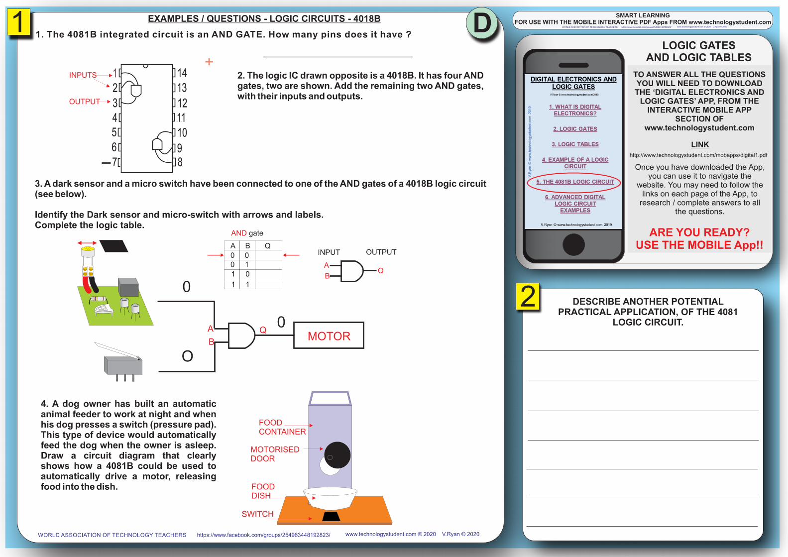
1. The 4081B integrated circuit is an AND GATE. How many pins does it have ?
234567
121110
98
13141
+
INPUTS
OUTPUT
2. The logic IC drawn opposite is a 4018B. It has four AND gates, two are shown. Add the remaining two AND gates, with their inputs and outputs.
A B Q
00
1
1
01
0
1
AND gate
A
BQ
INPUT OUTPUT
A
B
QMOTOR
0
O
0
3. A dark sensor and a micro switch have been connected to one of the AND gates of a 4018B logic circuit (see below).
Identify the Dark sensor and micro-switch with arrows and labels.Complete the logic table.
4. A dog owner has built an automatic animal feeder to work at night and when his dog presses a switch (pressure pad). This type of device would automatically feed the dog when the owner is asleep. Draw a circuit diagram that clearly shows how a 4081B could be used to automatically drive a motor, releasing food into the dish.
FOOD CONTAINER
MOTORISEDDOOR
FOODDISH
SWITCH
D
www.technologystudent.com © 2020https://www.facebook.com/groups/254963448192823/WORLD ASSOCIATION OF TECHNOLOGY TEACHERS V.Ryan © 2020
SMART LEARNING FOR USE WITH THE MOBILE INTERACTIVE PDF Apps FROM www.technologystudent.com
www.technologystudent.com © 2020https://www.facebook.com/groups/254963448192823/WORLD ASSOCIATION OF TECHNOLOGY TEACHERS V.Ryan © 2020
EXAMPLES / QUESTIONS - LOGIC CIRCUITS - 4018B

ARE YOU READY?USE THE MOBILE App!!
Once you have downloaded the App, you can use it to navigate the
website. You may need to follow the links on each page of the App, to
research / complete answers to all the questions.
LINK
ADVANCEDQUESTIONS
TO ANSWER ALL THE QUESTIONS YOU WILL NEED TO DOWNLOAD THE ‘DIGITAL ELECTRONICS AND
LOGIC GATES’ APP, FROM THE INTERACTIVE MOBILE APP
SECTION OF www.technologystudent.com
http://www.technologystudent.com/mobapps/digital1.pdf
USE THE APP TO HELP YOU ANSWER THE
FOLLOWING ADVANCED QUESTIONS.
SMART LEARNING - FOR USE WITH THE MOBILE INTERACTIVE PDF Apps FROM www.technologystudent.comwww.technologystudent.com © 2020https://www.facebook.com/groups/254963448192823/WORLD ASSOCIATION OF TECHNOLOGY TEACHERS V.Ryan © 2020
A B Q
LOWLOW
HIGH
HIGH
LOWHIGH
LOW
HIGH
LOWLOW
LOW
HIGH
AND gate
A
BQ
INPUT OUTPUT
A B Q
OFFOFF
ON
ON
OFFON
OFF
ON
OFFOFF
OFF
ON
AND gate
A
BQ
INPUT OUTPUT
A B Q
FALSE
FALSE
TRUE
TRUE
FALSE
TRUE
FALSE
TRUE
FALSE
FALSE
FALSE
TRUE
AND gate
A
BQ
INPUT OUTPUT
A B Q
00
1
1
01
0
1
00
0
1
AND gate
A
BQ
INPUT OUTPUT
A B Q
00
1
1
01
0
1
01
1
1
OR gate
A
BQ
INPUTOUTPUT
A B Q
00
1
1
01
0
1
11
1
0
NAND gate
A
BQ
INPUT OUTPUT
A B Q
00
1
1
01
0
1
10
0
0
NOR gate
A
BQ
INPUT OUTPUT
A Q
01
10
INVERTER gate
A Q
INPUT OUTPUT

EADVANCED QUESTIONS - LOGIC CIRCUITS
Below is the logic circuit for a simple house alarm. The alarm protects the front and back doors and six windows. Once the alarm is set if any of the doors or windows are opened the alarm will sound. The inputs for each of the gates representing the doors and windows can be connected to a vast
range of sensors (eg. movement and magnetic sensors).
On the circuit below the input states of each of the sensors are ‘0’ (false, low, off). This means that they have not detected an intruder. As a result the alarm does not sound.
0
0
0
0
0
0
0
0
0
WINDOW 1
WINDOW 2
0
0
0
WINDOW 3
WINDOW 4
0
0
0
WINDOW 5
WINDOW 6
0
0
0
FRONT DOOR
BACK DOOR
0
0
0
ALARM SOUNDS
A
B
C
D
E
F
G
TIMER0
0
0
0
0
0
0
0
0
0
0
0
0
0
0
0
0
0
0
0
0
0
A
B
C
D
E
F
G
0
WINDOW 1
WINDOW 2
0
0
WINDOW 3
WINDOW 4
1
0
WINDOW 5
WINDOW 6
0
0
FRONT DOOR
BACK DOOR
0
0
0
ALARM SOUNDS
A
B
C
D
E
F
G
TIMER
0
0
0
0
0
0
A
B
C
D
E
F
GJEFF HARDMANhe’s a
2. Why is a timer needed for the front and back doors?
3. Draw the correct symbol for gates E, F and G.
1. What type of gates have been used for the windows?
A thief breaks in through window 3. The logic state of the input changes to 1, high, on , True. Write the logic states of all the other inputs and outputs. Draw in the correct logic gates (see previous logic diagram). Remember the alarm must sound.
ww
w.t
ech
no
log
ystu
de
nt.
com
© 2
02
0h
ttp
s://
ww
w.f
ace
bo
ok.
com
/gro
up
s/2
54
96
34
48
19
28
23
/W
OR
LD
AS
SO
CIA
TIO
N O
F T
EC
HN
OL
OG
Y T
EA
CH
ER
SV
.Rya
n ©
20
20
ww
w.t
ech
no
log
ystu
de
nt.
com
© 2
02
0h
ttp
s://
ww
w.f
ace
bo
ok.
com
/gro
up
s/2
54
96
34
48
19
28
23
/W
OR
LD
AS
SO
CIA
TIO
N O
F T
EC
HN
OL
OG
Y T
EA
CH
ER
SV
.Rya
n ©
20
20

FADVANCED QUESTIONS - LOGIC CIRCUITS
An electronics company has developed a baby sitting device which warns parents when their child turns on a lamp next to the bed or when the temperature of the room falls.
Sensor is a temperature sensor which outputs ( ) when the room temperature A false 0, low, offfalls below a set level.
Sensor is a light sensor and is attached to a lamp. The sensor outputs ( ) when B true 1, high, onthe lamp is switched on.
SENSOR A
SENSOR B
NOT
OR TRANSDUCERDRIVER
BUZZER
1. What is a transducer driver and what is its function?A transducer driver is normally a circuit that amplifies a weak signal (current). In this case current from the OR gate is amplified by the transducer driver which in turn energises a relaying - activating the buzzer. A signal (current) from any gate is usually too weak to directly activate a buzzer.
On the circuit diagram complete the transducer driver and name it.
PRESETRESISTOR
TRAN
SIS
TOR
SLDR
BUZZER
RELAY
SENSOR TRANSDUCERDRIVER
BUZZER
LIGHT SENSOR ALLOWS CURRENT TO FLOW INTO THE TRANSISTORS WHEN
LIGHT SHINES ON IT.
NAME:WHEN RELAY IS
ENERGISED, CURRENT FLOWS THROUGH
BUZZER, CREATING SOUND.
SENSOR A
SENSOR B
NOT
OR TRANSDUCERDRIVER
BUZZERSOUNDS
2. The young child awakes and turns on a lamp next to her bed, changing the logic states of the outputs / inputs of the sensors and logic gates. On the logic circuit below, write the logic state of inputs / outputs of the sensors and gates.
SENSOR A
SENSOR B
NOT
TRANSDUCERDRIVER
BUZZERSOUNDS
3. As the child grows older she regularly gets out of bed and moves around during the night. A new sensor needs to be connected to the system to detect this movement. A micro-switch (SENSOR C) has been added to the system so that when the child opens her bedroom door the buzzer is activated. Complete the circuit below by adding the necessary gate.
1 0
0 1
SENSOR C1
OR
4. In the space opposite write/draw the logic table for your chosen gate.
B C Q
THREE INPUT OR GATE
INPUT OUTPUTA
OR
5. The electronics company has decided to add a circuit that will pulse the buzzer on and off. Name a circuit that could be used.
www.technologystudent.com © 2020https://www.facebook.com/groups/254963448192823/WORLD ASSOCIATION OF TECHNOLOGY TEACHERS V.Ryan © 2020
ww
w.t
ech
no
log
ystu
de
nt.
com
© 2
02
0h
ttp
s://
ww
w.f
ace
bo
ok.
com
/gro
up
s/2
54
96
34
48
19
28
23
/W
OR
LD
AS
SO
CIA
TIO
N O
F T
EC
HN
OL
OG
Y T
EA
CH
ER
SV
.Rya
n ©
20
20
GADVANCED QUESTIONS - LOGIC CIRCUITS
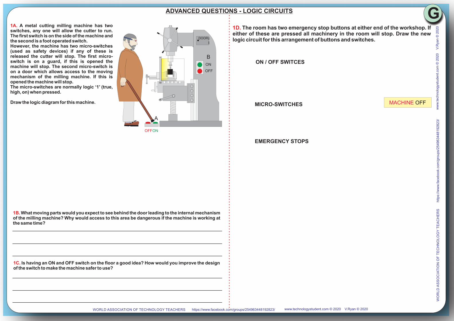
1A. A metal cutting milling machine has two switches, any one will allow the cutter to run. The first switch is on the side of the machine and the second is a foot operated switch.However, the machine has two micro-switches (used as safety devices) if any of these is released the cutter will stop. The first micro-switch is on a guard, if this is opened the machine will stop. The second micro-switch is on a door which allows access to the moving mechanism of the milling machine. If this is opened the machine will stop.The micro-switches are normally logic ‘1’ (true, high, on) when pressed.
Draw the logic diagram for this machine.
ON
OFF
ONOFF
DOOR
A
B
1B. What moving parts would you expect to see behind the door leading to the internal mechanism of the milling machine? Why would access to this area be dangerous if the machine is working at the same time?
1C. Is having an ON and OFF switch on the floor a good idea? How would you improve the design of the switch to make the machine safer to use?
1D. The room has two emergency stop buttons at either end of the workshop. If either of these are pressed all machinery in the room will stop. Draw the new logic circuit for this arrangement of buttons and switches.
MACHINE OFFMICRO-SWITCHES
ON / OFF SWITCES
EMERGENCY STOPS
www.technologystudent.com © 2020https://www.facebook.com/groups/254963448192823/WORLD ASSOCIATION OF TECHNOLOGY TEACHERS V.Ryan © 2020
ww
w.t
ech
no
log
ystu
de
nt.
com
© 2
02
0h
ttp
s://
ww
w.f
ace
bo
ok.
com
/gro
up
s/2
54
96
34
48
19
28
23
/W
OR
LD
AS
SO
CIA
TIO
N O
F T
EC
HN
OL
OG
Y T
EA
CH
ER
SV
.Rya
n ©
20
20

HADVANCED QUESTIONS - LOGIC CIRCUITS
1. A local systems designer has developed a system to control street lights. The street lights can be turned on manually, or by the use of a timer so long as a light sensing unit indicates that it is dark.Below is an incomplete logic circuit for the control system.
SWITCH
TIMER
LIGHTSENSOR GATE X
GATE Y
GATE Z STREETLIGHTS
A
B
C
DE
Q
1A. Complete the diagram below using the correct logic gates. Note the output of the dark/light sensor is ‘1’ (true, high, on) when it is light. The lights must be turned during the dark of night.
ON = 1
OFF = 0
DARK = 0
LIGHT = 1
ON = 1
OFF = 0
OR
AND
NOT
SWITCH
TIMER
LIGHTSENSOR
A
B
C
ON = 1
DARK = 0
ON = 1
STREETLIGHTS
1
1
11
11
Below is the logic circuit showing the logic states of inputs and outputs of all the gates when the street lights are .ON
1B. Name the logic gates you have used:
GATE X ................. GATE Y ............... GATE Z ...............
OR
AND
NOT
SWITCH
TIMER
LIGHTSENSOR
A
B
C
OFF = 0
LIGHT = 1
STREETLIGHTS
0
0
00
00
Below is the logic circuit showing the logic states of inputs and outputs of all the gates when the street lights are .OFF
OFF = 0
ON
OFF
OR
AND
NOT
SWITCH
TIMER
LIGHTSENSOR
A
B
C
STREETLIGHTS
1C. On the logic circuit below, write the logic states of all inputs and outputs for the following:It is night time, the manual switch is off and the timer is ‘on’. Will the street lights be on or off ?
www.technologystudent.com © 2020https://www.facebook.com/groups/254963448192823/WORLD ASSOCIATION OF TECHNOLOGY TEACHERS V.Ryan © 2020
ww
w.t
ech
no
log
ystu
de
nt.
com
© 2
02
0h
ttp
s://
ww
w.f
ace
bo
ok.
com
/gro
up
s/2
54
96
34
48
19
28
23
/W
OR
LD
AS
SO
CIA
TIO
N O
F T
EC
HN
OL
OG
Y T
EA
CH
ER
SV
.Rya
n ©
20
20