© 2009 pearson education, inc. publishing as prentice hall 4-1 multi-switch ethernet lan operation
TRANSCRIPT
© 2009 Pearson Education, Inc. Publishing as Prentice Hall 4-1
Multi-Switch Ethernet LAN Operation

© 2009 Pearson Education, Inc. Publishing as Prentice Hall4-2
Data Link Using Multiple Switches
OriginalSignal
ReceivedSignal
ReceivedSignal
ReceivedSignalRegenerated
SignalRegenerated
Signal
UTP UTP62.5/125Multimode Fiber
100BASE-TX(100 m maximum)
Physical Link
100BASE-TX(100 m maximum)
Physical Link
1000BASE-SX(220 m maximum)
Physical Link
Each trunk line along the way has a distance limit
© 2009 Pearson Education, Inc. Publishing as Prentice Hall4-3
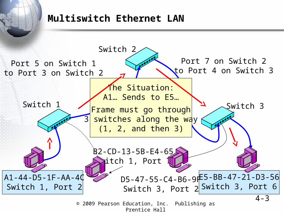
Multiswitch Ethernet LAN
Switch 2
Switch 1 Switch 3
Port 5 on Switch 1to Port 3 on Switch 2
Port 7 on Switch 2to Port 4 on Switch 3
A1-44-D5-1F-AA-4CSwitch 1, Port 2
E5-BB-47-21-D3-56Switch 3, Port 6
D5-47-55-C4-B6-9FSwitch 3, Port 2
B2-CD-13-5B-E4-65Switch 1, Port 7
The Situation:A1… Sends to E5…
Frame must go through3 switches along the way
(1, 2, and then 3)
© 2009 Pearson Education, Inc. Publishing as Prentice Hall4-4
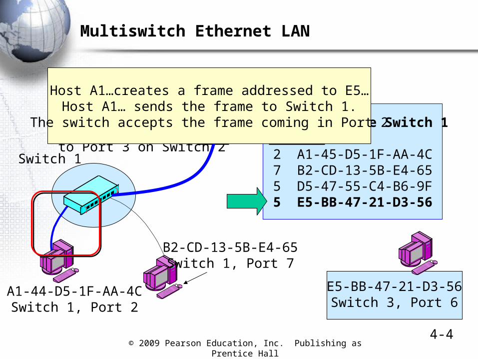
Multiswitch Ethernet LAN
Switching Table Switch 1Port Station
2 A1-45-D5-1F-AA-4C7 B2-CD-13-5B-E4-655 D5-47-55-C4-B6-9F5 E5-BB-47-21-D3-56
Switch 2
Switch 1
Port 5 on Switch 1to Port 3 on Switch 2
A1-44-D5-1F-AA-4CSwitch 1, Port 2
B2-CD-13-5B-E4-65Switch 1, Port 7
E5-BB-47-21-D3-56Switch 3, Port 6
Host A1…creates a frame addressed to E5…Host A1… sends the frame to Switch 1.
The switch accepts the frame coming in Port 2

© 2009 Pearson Education, Inc. Publishing as Prentice Hall4-5
Multiswitch Ethernet LAN
Switching Table Switch 1Port Station
2 A1-45-D5-1F-AA-4C7 B2-CD-13-5B-E4-655 D5-47-55-C4-B6-9F5 E5-BB-47-21-D3-56
Switch 2
Switch 1
Port 5 on Switch 1to Port 3 on Switch 2
A1-44-D5-1F-AA-4CSwitch 1, Port 2
B2-CD-13-5B-E4-65Switch 1, Port 7
E5-BB-47-21-D3-56Switch 3, Port 6
On Switch 1
Switch 1 looks up thedestination MAC addressand notes the port number
for that address (Port 5)
Switch 1 sends the frameout Port 5
Switch 2 is out that port
© 2009 Pearson Education, Inc. Publishing as Prentice Hall4-6
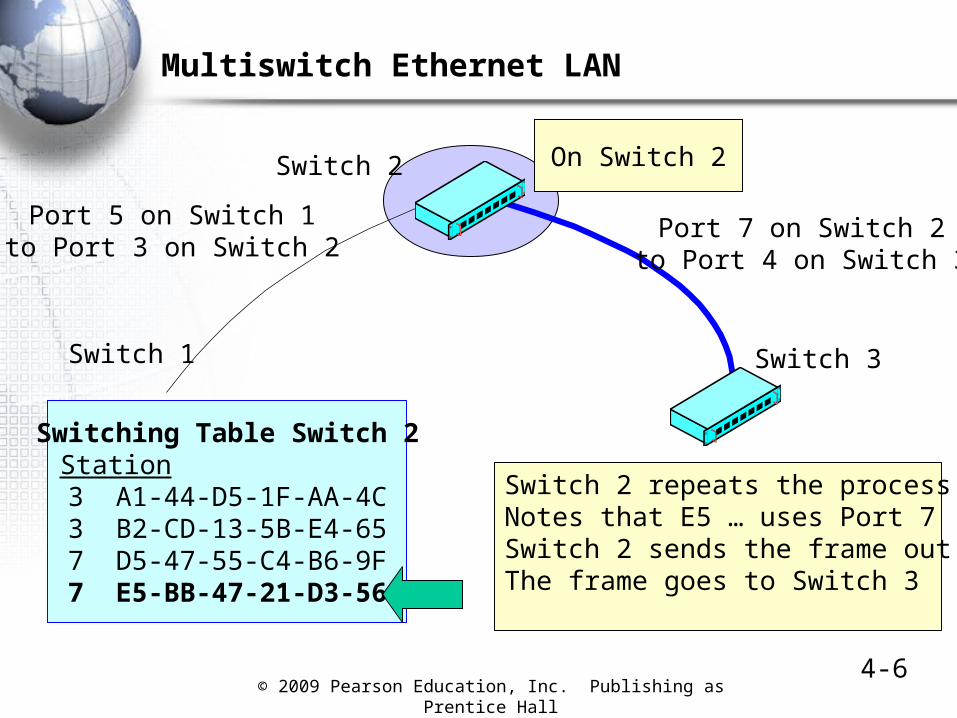
Multiswitch Ethernet LAN
Switch 2
Switch 1 Switch 3
Port 5 on Switch 1to Port 3 on Switch 2
Port 7 on Switch 2to Port 4 on Switch 3
Switching Table Switch 2Port Station
3 A1-44-D5-1F-AA-4C3 B2-CD-13-5B-E4-657 D5-47-55-C4-B6-9F7 E5-BB-47-21-D3-56
On Switch 2
Switch 2 repeats the processNotes that E5 … uses Port 7Switch 2 sends the frame out Port 7The frame goes to Switch 3
© 2009 Pearson Education, Inc. Publishing as Prentice Hall4-7
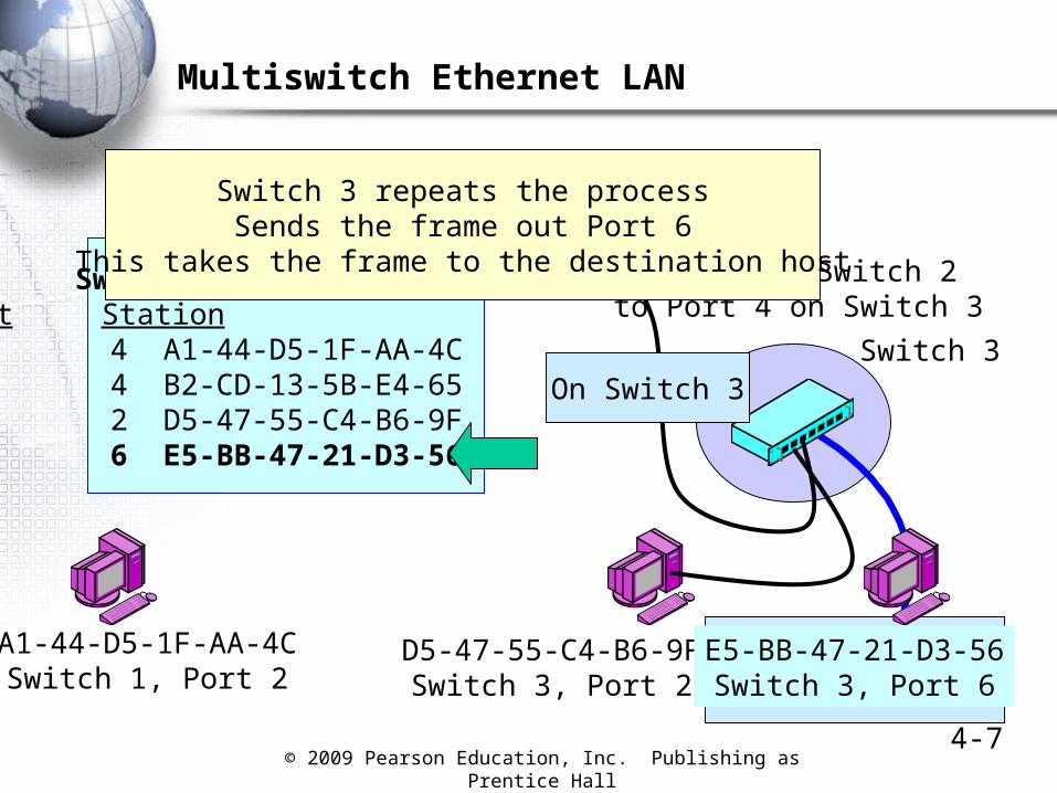
Multiswitch Ethernet LAN
Switch 2
Switch 3
Port 7 on Switch 2to Port 4 on Switch 3
A1-44-D5-1F-AA-4CSwitch 1, Port 2
D5-47-55-C4-B6-9FSwitch 3, Port 2
Switching Table Switch 3Port Station
4 A1-44-D5-1F-AA-4C4 B2-CD-13-5B-E4-652 D5-47-55-C4-B6-9F6 E5-BB-47-21-D3-56
E5-BB-47-21-D3-56Switch 3, Port 6
On Switch 3
Switch 3 repeats the processSends the frame out Port 6
This takes the frame to the destination host
© 2009 Pearson Education, Inc. Publishing as Prentice Hall
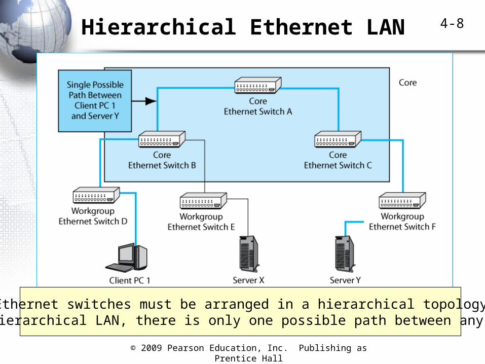
4-8Hierarchical Ethernet LAN
Ethernet switches must be arranged in a hierarchical topologyIn a hierarchical LAN, there is only one possible path between any hosts
© 2009 Pearson Education, Inc. Publishing as Prentice Hall4-9
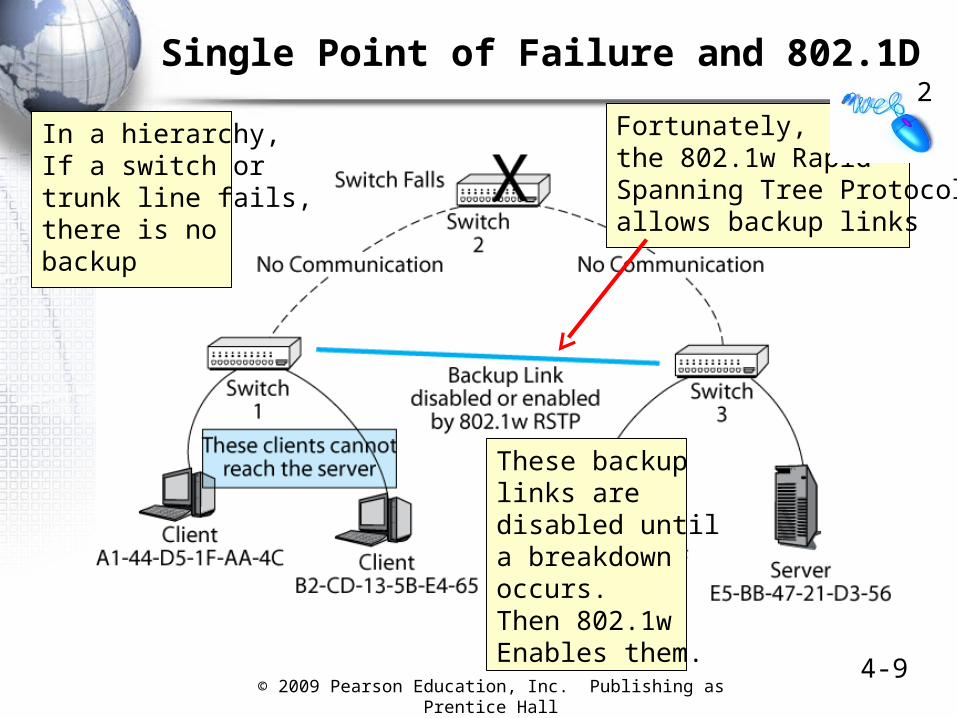
Single Point of Failure and 802.1D
In a hierarchy,If a switch ortrunk line fails,there is nobackup
These backuplinks aredisabled untila breakdownoccurs.Then 802.1wEnables them.
Fortunately,the 802.1w RapidSpanning Tree Protocolallows backup links
2
© 2009 Pearson Education, Inc. Publishing as Prentice Hall4-10
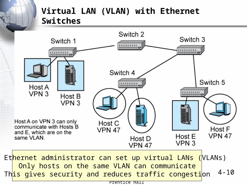
Virtual LAN (VLAN) with Ethernet Switches
The Ethernet administrator can set up virtual LANs (VLANs)Only hosts on the same VLAN can communicateThis gives security and reduces traffic congestion
© 2009 Pearson Education, Inc. Publishing as Prentice Hall4-11
Handling Momentary Traffic Peaks with Overprovisioning and Priority
Traffic
Network Capacity
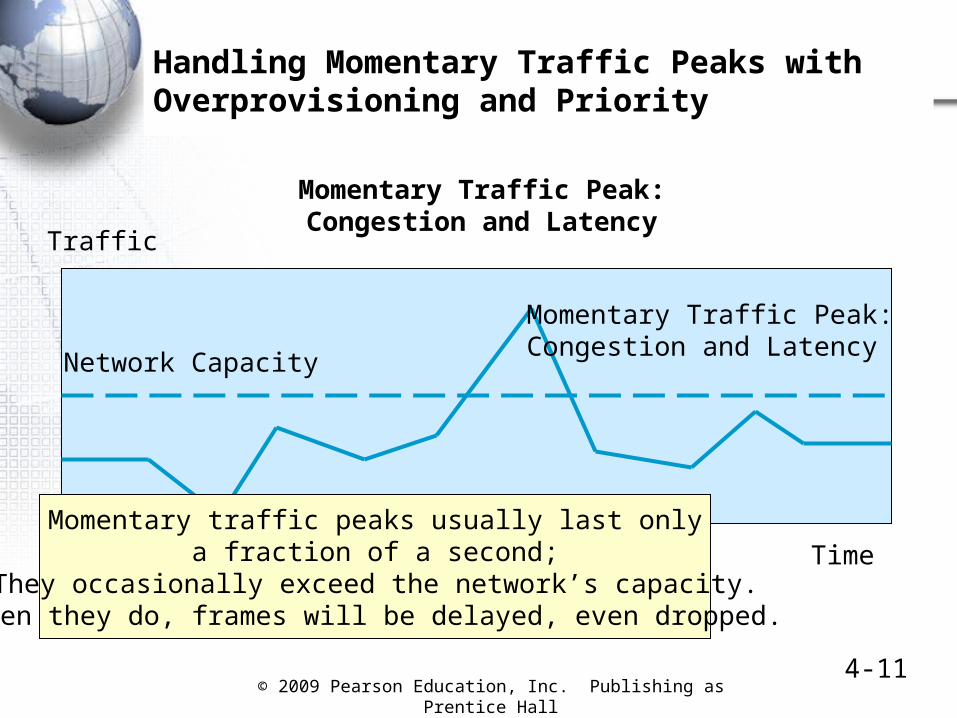
Momentary Traffic Peak:Congestion and Latency
Time
Momentary Traffic Peak:Congestion and Latency
Momentary traffic peaks usually last onlya fraction of a second;
They occasionally exceed the network’s capacity.When they do, frames will be delayed, even dropped.
© 2009 Pearson Education, Inc. Publishing as Prentice Hall4-12
Handling Momentary Traffic Peaks with Overprovisioning and Priority
Traffic
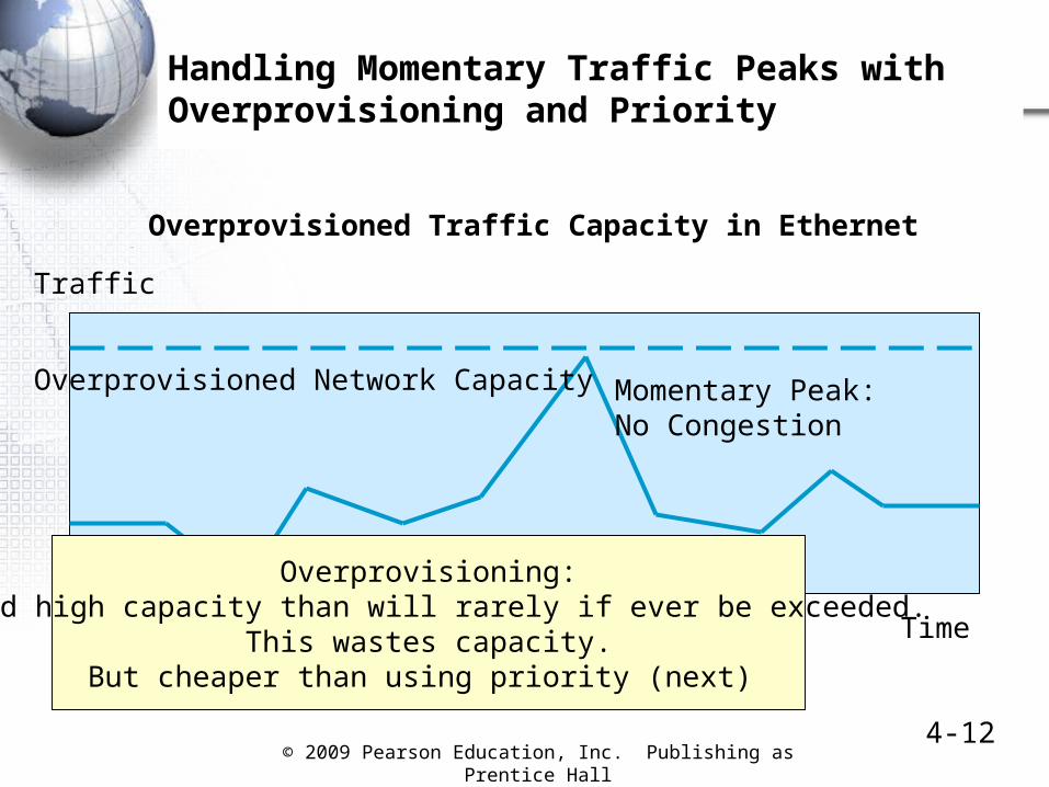
Overprovisioned Network Capacity Momentary Peak:No Congestion
Time
Overprovisioned Traffic Capacity in Ethernet
Overprovisioning:Build high capacity than will rarely if ever be exceeded.
This wastes capacity.But cheaper than using priority (next)
© 2009 Pearson Education, Inc. Publishing as Prentice Hall4-13
Handling Momentary Traffic Peaks with Overprovisioning and Priority
Traffic
Network Capacity
MomentaryPeak
Time
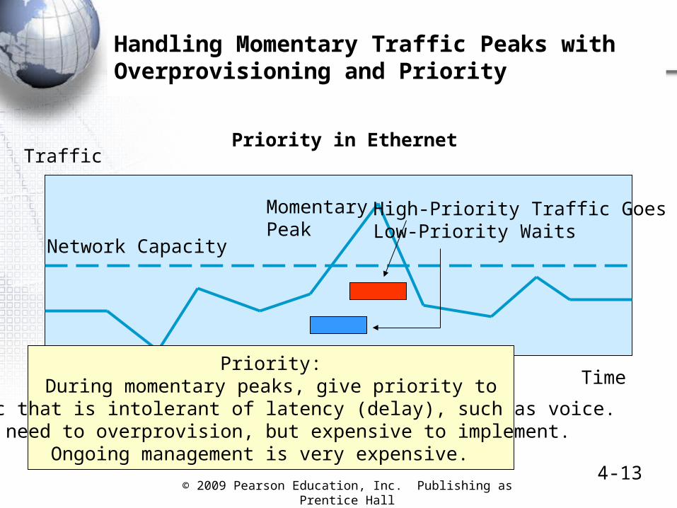
Priority in Ethernet
High-Priority Traffic GoesLow-Priority Waits
Priority:During momentary peaks, give priority to
traffic that is intolerant of latency (delay), such as voice.No need to overprovision, but expensive to implement.
Ongoing management is very expensive.
© 2009 Pearson Education, Inc. Publishing as Prentice Hall4-14
Hub versus Switch Operation
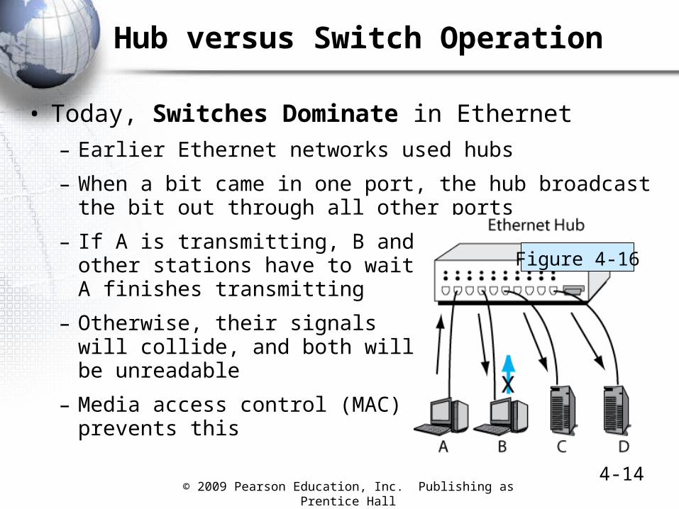
• Today, Switches Dominate in Ethernet
– Earlier Ethernet networks used hubs
– When a bit came in one port, the hub broadcast the bit out through all other ports
– If A is transmitting, B and allother stations have to wait untilA finishes transmitting
– Otherwise, their signalswill collide, and both willbe unreadable
– Media access control (MAC)prevents this
Figure 4-16
© 2009 Pearson Education, Inc. Publishing as Prentice Hall4-15
Switch Purchasing Considerations
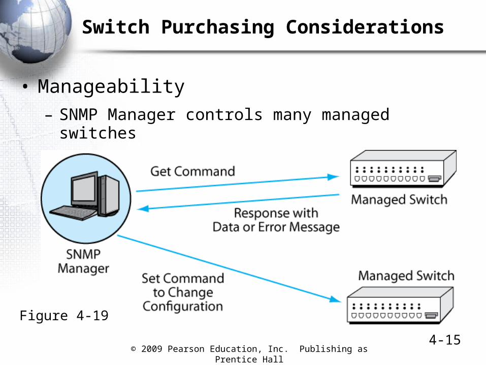
• Manageability
– SNMP Manager controls many managed switches
Figure 4-19
© 2009 Pearson Education, Inc. Publishing as Prentice Hall4-16
Switch Purchasing Considerations
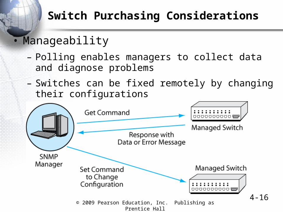
• Manageability
– Polling enables managers to collect data and diagnose problems
– Switches can be fixed remotely by changing their configurations
© 2009 Pearson Education, Inc. Publishing as Prentice Hall4-17
Physical and Electrical Features
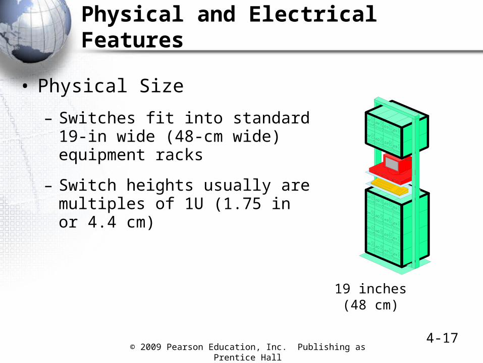
• Physical Size
– Switches fit into standard 19-in wide (48-cm wide) equipment racks
– Switch heights usually are multiples of 1U (1.75 in or 4.4 cm)
19 inches(48 cm)
© 2009 Pearson Education, Inc. Publishing as Prentice Hall4-18
Physical and Electrical Features
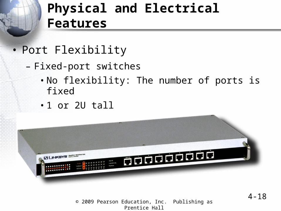
• Port Flexibility
– Fixed-port switches
• No flexibility: The number of ports is fixed
• 1 or 2U tall
• Most workgroup switches are fixed-port switches

© 2009 Pearson Education, Inc. Publishing as Prentice Hall4-19
Physical and Electrical Features
• Port Flexibility
– Stackable switches
• Fixed number of ports
• 1U or 2U tall
• High-speed interconnect bus connects stacked switches
• Ports can be added in increments of as few as 12

© 2009 Pearson Education, Inc. Publishing as Prentice Hall4-20
Physical and Electrical Features
• Port Flexibility
– Modular switches
• 1U or 2U tall
• Contain one or a few slots
• Each slot module contains 1 to 4 ports
Module

© 2009 Pearson Education, Inc. Publishing as Prentice Hall 4-21
Physical and Electrical Features
• Port Flexibility
– Chassis switches
• Several U tall
• Contain several expansion slots
• Each expansion board contains several slots
• Most core switches are chassis switches

© 2009 Pearson Education, Inc. Publishing as Prentice Hall4-22
Physical and Electrical Features
• Uplink Ports
– Normal Ethernet RJ-45 switch ports transmit on Pins 3 and 6 and listen on Pins 1 and 2
• If you connect two normal switch ports on different switches via UTP cords, the ports will not be able to communicate
• A crossover cable solves this problem
NormalSwitch
Port
NormalSwitch PortOn Parent
SwitchPins3 & 6
Pins1 & 2
CrossoverCable
Pins1 & 2
Pins3 & 6
© 2009 Pearson Education, Inc. Publishing as Prentice Hall 4-23
Ethernet Security
© 2009 Pearson Education, Inc. Publishing as Prentice Hall 4-24
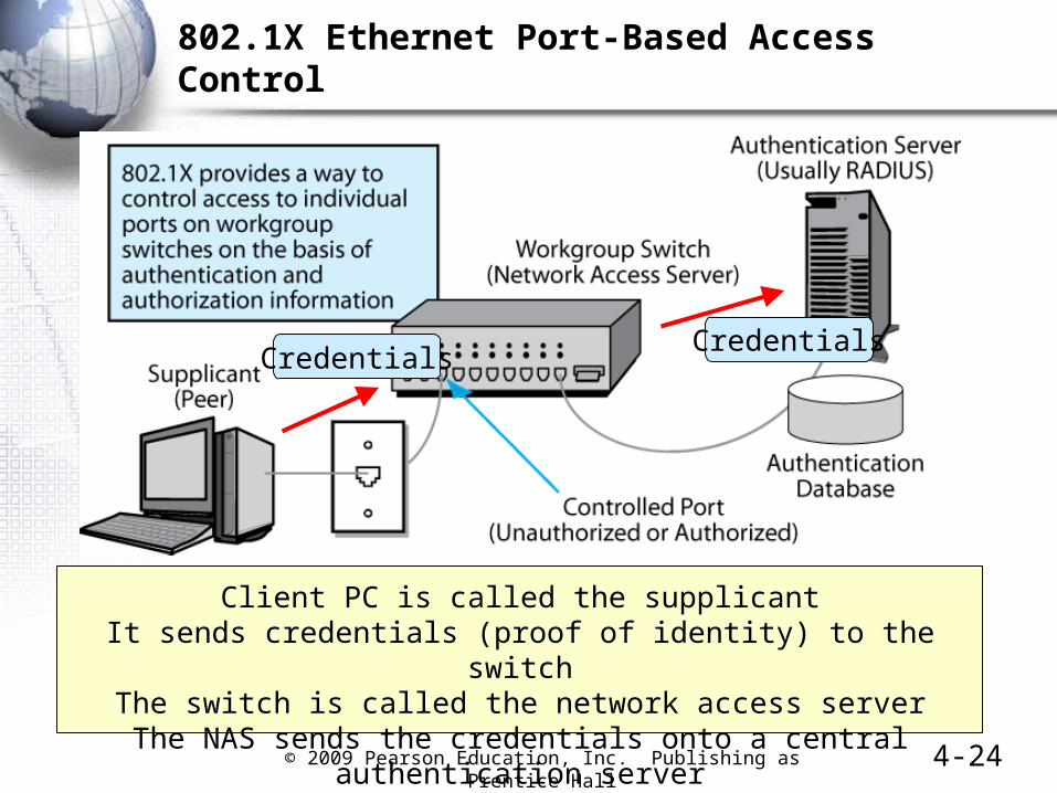
802.1X Ethernet Port-Based Access Control
Client PC is called the supplicantIt sends credentials (proof of identity) to the switch
The switch is called the network access serverThe NAS sends the credentials onto a central authentication server
CredentialsCredentials
© 2009 Pearson Education, Inc. Publishing as Prentice Hall4-25
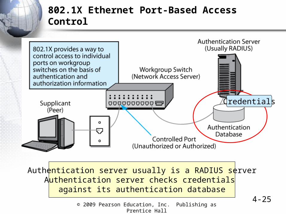
802.1X Ethernet Port-Based Access Control
Authentication server usually is a RADIUS serverAuthentication server checks credentials
against its authentication database
Credentials
© 2009 Pearson Education, Inc. Publishing as Prentice Hall4-26
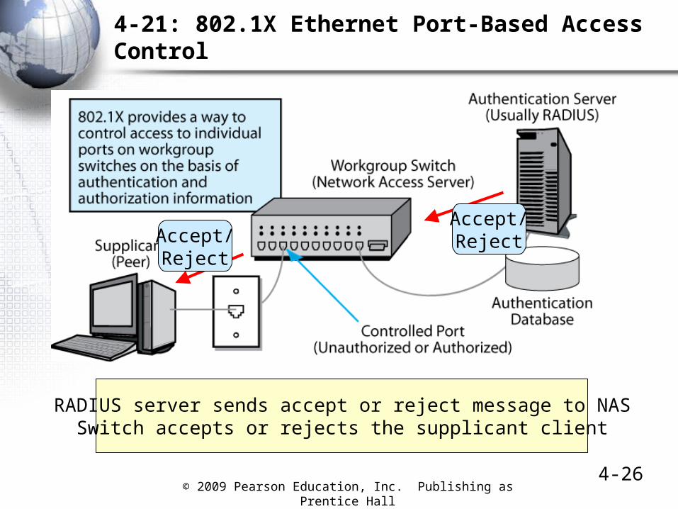
4-21: 802.1X Ethernet Port-Based Access Control
RADIUS server sends accept or reject message to NASSwitch accepts or rejects the supplicant client
Accept/RejectAccept/
Reject