© 2009 pearson education, inc. publishing as prentice hall 4-1 ethernet lans chapter 4 updated...
TRANSCRIPT

© 2009 Pearson Education, Inc. Publishing as Prentice Hall 4-1
Ethernet LANs
Chapter 4Updated January 2009
Raymond Panko’sBusiness Data Networks and Telecommunications, 7th edition
May only be used by adopters of the book

© 2009 Pearson Education, Inc. Publishing as Prentice Hall4-2
Orientation
• Chapters 2 and 3 Looked at Standards
– Chapter 2: Layered standards (data link to application)
– Chapter 3: Physical layer standards
• Chapters 4-7 Deal With Single Networks: Switched and Wireless
– Chapter 4: Ethernet LANs
– Chapter 5: Wireless LANs
– Chapters 6 and 7: WANs
– Flow is from LANs to WANs (familiar to less familiar)

© 2009 Pearson Education, Inc. Publishing as Prentice Hall4-3
4-1: A Short History of Ethernet Standards
• Early History of Ethernet Standards
– Developed at the Xerox Palo Alto Research Center by Metcalfe and Boggs
– Standardized by Xerox, Intel, and Digital Equipment Corporation
– Developed the Ethernet I and Ethernet II standards in the early 1980s

© 2009 Pearson Education, Inc. Publishing as Prentice Hall4-4
4-1: A Short History of Ethernet Standards
• The 802 Committee
– In the early 1980s, development passed to the Institute for Electrical and Electronics Engineers (IEEE)
• The IEEE created the 802 LAN/MAN Standards Committee for LAN standards
– This committee is usually called the 802 Committee

© 2009 Pearson Education, Inc. Publishing as Prentice Hall4-5
4-1: A Short History of Ethernet Standards
• The 802 Committee
– The 802 Committee creates working groups for specific types of standards
• 802.1 for general standards, including security standards
• 802.3 for Ethernet standards
• 802.11 for wireless LAN standards
• 802.16 for WiMax wireless metropolitan area network standards
© 2009 Pearson Education, Inc. Publishing as Prentice Hall4-6
4-1: A Short History of Ethernet Standards
• The 802.3 Working Group
– This group is in charge of creating Ethernet standards
– The terms 802.3 and Ethernet are interchangeable today
– Ethernet standards govern physical layer processes
– Ethernet also governs data link layer standards (frame organization, switch operation, etc.)

© 2009 Pearson Education, Inc. Publishing as Prentice Hall4-7
4-1: A Short History of Ethernet Standards
• Ethernet Standards are OSI Standards
– Layer 1 and Layer 2 standards are almost universally OSI standards
– Ethernet is no exception
– ISO must ratify them
• In practice, when the 802.3 Working Group finishes standards, vendors begin building compliant products

© 2009 Pearson Education, Inc. Publishing as Prentice Hall 4-8
Ethernet Physical Layer Standards
© 2009 Pearson Education, Inc. Publishing as Prentice Hall4-9
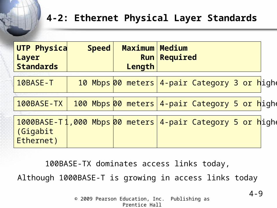
4-2: Ethernet Physical Layer Standards
UTP PhysicalLayerStandards
MediumRequired
MaximumRun
Length
Speed
100BASE-TX 4-pair Category 5 or higher100 meters100 Mbps
1000BASE-T(GigabitEthernet)
4-pair Category 5 or higher100 meters1,000 Mbps
10BASE-T 4-pair Category 3 or higher100 meters10 Mbps
100BASE-TX dominates access links today,
Although 1000BASE-T is growing in access links today

© 2009 Pearson Education, Inc. Publishing as Prentice Hall4-10
Fiber PhysicalLayerStandards
Medium850 nm light (inexpensive)Multimode fiber
MaximumRun
Length
Speed
1000BASE-SX 275 m1 Gbps
1000BASE-SX 500 m1 Gbps
1000BASE-SX 220 m1 Gbps
1000BASE-SX 550 m1 Gbps
4-2: Ethernet Physical Layer Standards
62.5microns
160MHz-km
62.5 200
50 400
50 500
The 1000BASE-SX optical fiber standard dominates trunk links todayS means that the standard uses short wavelength light (850 nm)

© 2009 Pearson Education, Inc. Publishing as Prentice Hall4-11
4-2: Ethernet Physical Layer Standards
• For Higher Speeds
– Many 10 Gbps Ethernet physical layer standards have been developed
• Both optical fiber and twisted-pair versions have been developed
• Most operate at a full 10 Gbps
• Some operation at 9.95328 Gbps for compatibility with the SONET WAN standard that operates at this speed (See Chapter 6 and Module C)
– The 40 Gbps and 100 Gbps Ethernet standards are under preliminary development

© 2009 Pearson Education, Inc. Publishing as Prentice Hall4-12
4-3: Baseband Versus Broadband Transmission
The “BASE” in Ethernet standards refers to baseband transmission.
In baseband transmission, the signal is merely injected into the wire or fiber cord and then propagates down the wire.
This is inexpensive, so baseband transmission dominatesEthernet transmission today.

© 2009 Pearson Education, Inc. Publishing as Prentice Hall4-13
4-3: Baseband Versus Broadband Transmission
In broadband transmission, the signal is modulated topropagate in a radio channel.
This inexpensive, so broadband transmission is rare.
Broadband transmission cable modem service,which has its own standards.

© 2009 Pearson Education, Inc. Publishing as Prentice Hall4-14
4-4: Link Aggregation (Trunking or Bonding)
What if you need 1.7 Gbps?
One 1000BASE-SXconnection between twoswitches will only give 1 Gbps.
Installing a 10 Gbps portwould be expensive
Today, most switches allowyou to connect two or moreports.
Connecting two ports give youThe needed 2 Gbps.
This is called link aggregation,Trunking, or bonding.
1000BASE-X switch
1000BASE-X switch
Two bonded1000BASE-SX links

© 2009 Pearson Education, Inc. Publishing as Prentice Hall4-15
4-5: Data Link Using Multiple Switches
OriginalSignal
ReceivedSignal
RegeneratedSignal
Switches regenerate signals before sending them out;this removes propagation effects
It therefore allows signals to travel farther

© 2009 Pearson Education, Inc. Publishing as Prentice Hall4-16
Figure 4-5: Data Link Using Multiple Switches
OriginalSignal
ReceivedSignal
ReceivedSignal
ReceivedSignalRegenerated
Signal RegeneratedSignal
Thanks to regeneration, signals can travel far acrossa series of switches

© 2009 Pearson Education, Inc. Publishing as Prentice Hall4-17
4-5: Data Link Using Multiple Switches
OriginalSignal
ReceivedSignal
ReceivedSignal
ReceivedSignalRegenerated
SignalRegenerated
Signal
UTP UTP62.5/125Multimode Fiber
100BASE-TX(100 m maximum)
Physical Link
100BASE-TX(100 m maximum)
Physical Link
1000BASE-SX(220 m maximum)
Physical Link
Each trunk line along the way has a distance limit

© 2009 Pearson Education, Inc. Publishing as Prentice Hall4-18
4-5: Data Link Using Multiple Switches
Station-to-station data link does not have a maximum distance(420 m maximum distance in this example)
OriginalSignal
ReceivedSignal
ReceivedSignal
ReceivedSignalRegenerated
Signal RegeneratedSignal
UTP UTP62.5/125Multimode Fiber
100BASE-TX(100 m maximum)
Physical Link
100BASE-TX(100 m maximum)
Physical Link
1000BASE-SX(220 m maximum)
Physical Link
© 2009 Pearson Education, Inc. Publishing as Prentice Hall 4-19
Ethernet Data Link Layer Standards
The MAC Layer:Frame Organization
Switch Operation

© 2009 Pearson Education, Inc. Publishing as Prentice Hall4-20
Figure 4-6: Layering in 802 Networks
TCP/IP InternetLayer Standards(IP, ARP, etc.)
Other InternetLayer Standards
(IPX, etc.)
802.2
Ethernet 802.3 MAC LayerStandard
Physical Layer
MediaAccessControlLayer
Non-EthernetMAC Standards
(802.5,802.11, etc.)
100BASE-TX
1000Base-
SX…
LogicalLink
ControlLayer
Non-EthernetPhysical
LayerStandards
(802.11, etc.)
DataLink
Layer
Internet LayerThe 802 LAN/MAN Standards Committee
subdivided the data link layer
The media access control (MAC) layerhandles details specific to a
particular technology (Ethernet 802.3,802.11 for wireless LANs, etc.)
The logical link control layerhandles some general functions:
Connection to the internet layer, etc.;Not important to corporatenetworking professionals

© 2009 Pearson Education, Inc. Publishing as Prentice Hall4-21
Figure 4-6: Layering in 802 Networks
TCP/IP InternetLayer Standards(IP, ARP, etc.)
Other InternetLayer Standards
(IPX, etc.)
802.2
Ethernet 802.3 MAC LayerStandard
Physical Layer
MediaAccessControlLayer
Non-EthernetMAC Standards
(802.5,802.11, etc.)
100BASE-TX
1000BASE-
SX…
LogicalLink
ControlLayer
Non-EthernetPhysical
LayerStandards
(802.11, etc.)
DataLink
Layer
Internet LayerEthernet has many physical layer standards (Fig. 4-2)
But Ethernet only has a single MAC standard(The 802.3 MAC Layer Standard)

© 2009 Pearson Education, Inc. Publishing as Prentice Hall4-22
4-7: The Ethernet MAC-Layer Frame

© 2009 Pearson Education, Inc. Publishing as Prentice Hall4-23
4-7: The Ethernet MAC-Layer Frame
• Header
– Preamble Field
• A series of 7 octets
• Each octet is 10101010
• Provides a synchronizing signal for the receiver’s clock
• Like a quarterback saying, “Hut one, hut two, hike!”
– Start of Frame Delimiter Field
• A single octet of 10101011 (does not end in 10)
• Finishes the synchronization
Preamble (7 octets)
Start of Frame Delimiter (1 octet)

© 2009 Pearson Education, Inc. Publishing as Prentice Hall4-24
4-7: The Ethernet MAC-Layer Frame
• Header
– Destination and sourceMAC addresses
– Each is 48 bits long
– Computers and switches work with the 48-bit numbers
– For humans, converted into hexadecimal notation
• Base 16
– Look like: A1-1B-23-DF-FF-00
• Six pairs of symbols separated by dashes
• Each symbol represents four bits
• Symbols are 0 through 9 or A through F
Start of Frame Delimiter (1 octet)
Destination MAC Address (48 bits)
Source MAC Address (48 bits)

© 2009 Pearson Education, Inc. Publishing as Prentice Hall4-25
Figure 4-8: Hexadecimal Notation
4 Bits* Decimal(Base 10)
Hexadecimal(Base 16)
4 Bits* Decimal(Base 10)
Hexadecimal(Base 16)
0000 0 0 hex 1000 8 8 hex
0001 1 1 hex 1001 9 9 hex
0010 2 2 hex 1010 10 A hex
0011 3 3 hex 1011 11 B hex
0100 4 4 hex 1100 12 C hex
0101 5 5 hex 1101 13 D hex
0110 6 6 hex 1110 14 E hex
0111 7 7 hex 1111 15 F hex
*Note: With 4 bits, there can be 24 = 16 possible “Hex” symbols…

© 2009 Pearson Education, Inc. Publishing as Prentice Hall4-26
Figure 4-8: Hexadecimal Notation
• To convert a 48-bit MAC address to “hex”
– Short for hexadecimal (Base 16) counting
– Divide a MAC address into 6 octets
– Divide each octet into two 4-bit “nibbles”
• So 10000001 becomes 1000 0001
– Change each nibble to a hex symbol
– 1000 = A and 0001 is 1
– Write the two hex symbols together as A1
– Separate the six octets of the MAC address with dashes
• A1-2B-39-FD-FF-FF
© 2009 Pearson Education, Inc. Publishing as Prentice Hall4-27
4-7: Ethernet MAC Layer Frame
• Length
– Length field gives the length of the data field in octets
• Data Field
– LLC subheader (7 octets) that describes the contents of the rest of the data field
– Followed (usually) by an IP packet
• PAD
– Added by sender if the data field is less than 46 octets
– If added, PAD is long enough to bring the data field plus the PAD to 46 octets

© 2009 Pearson Education, Inc. Publishing as Prentice Hall4-28
4-7: Ethernet MAC Layer Frame
• Question 1
– If the length field has the value 150, how long is the IP packet it carries?
• Question 2
– If the length field value is 400, how long is the PAD?
• Question 3
– If the length field value is 15,
– How long is the IP packet in the data field?
– How long is the PAD?

© 2009 Pearson Education, Inc. Publishing as Prentice Hall4-29
4-7: Ethernet MAC Layer Frame
• Trailer
– Frame Check Sequence
• 4-octet field
• Sender calculates a number based on the contents of the other fields, places it into the frame check sequence field
• Receiver redoes the calculation on the values in the received frame
• If the receiver’s number is different from the sender’s, there has been a transmission error
– The receiver drops the frame– There is no retransmission

© 2009 Pearson Education, Inc. Publishing as Prentice Hall 4-30
Multi-Switch Ethernet LAN Operation

© 2009 Pearson Education, Inc. Publishing as Prentice Hall4-31
4-9: Multiswitch Ethernet LAN
Switch 2
Switch 1 Switch 3
Port 5 on Switch 1to Port 3 on Switch 2
Port 7 on Switch 2to Port 4 on Switch 3
A1-44-D5-1F-AA-4CSwitch 1, Port 2
E5-BB-47-21-D3-56Switch 3, Port 6
D5-47-55-C4-B6-9FSwitch 3, Port 2
B2-CD-13-5B-E4-65Switch 1, Port 7
The Situation:A1… Sends to E5…
Frame must go through3 switches along the way
(1, 2, and then 3)

© 2009 Pearson Education, Inc. Publishing as Prentice Hall4-32
4-9: Multiswitch Ethernet LAN
Switching Table Switch 1Port Station
2 A1-45-D5-1F-AA-4C7 B2-CD-13-5B-E4-655 D5-47-55-C4-B6-9F5 E5-BB-47-21-D3-56
Switch 2
Switch 1
Port 5 on Switch 1to Port 3 on Switch 2
A1-44-D5-1F-AA-4CSwitch 1, Port 2
B2-CD-13-5B-E4-65Switch 1, Port 7
E5-BB-47-21-D3-56Switch 3, Port 6
Host A1…creates a frame addressed to E5…Host A1… sends the frame to Switch 1.
The switch accepts the frame coming in Port 2
© 2009 Pearson Education, Inc. Publishing as Prentice Hall4-33
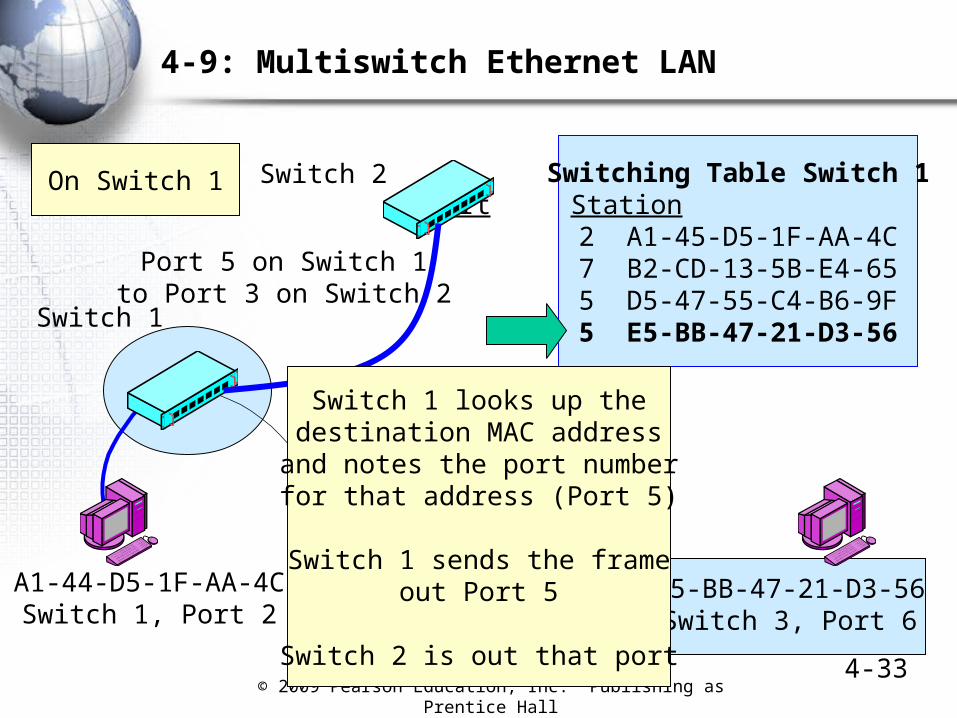
4-9: Multiswitch Ethernet LAN
Switching Table Switch 1Port Station
2 A1-45-D5-1F-AA-4C7 B2-CD-13-5B-E4-655 D5-47-55-C4-B6-9F5 E5-BB-47-21-D3-56
Switch 2
Switch 1
Port 5 on Switch 1to Port 3 on Switch 2
A1-44-D5-1F-AA-4CSwitch 1, Port 2
B2-CD-13-5B-E4-65Switch 1, Port 7
E5-BB-47-21-D3-56Switch 3, Port 6
On Switch 1
Switch 1 looks up thedestination MAC addressand notes the port number
for that address (Port 5)
Switch 1 sends the frameout Port 5
Switch 2 is out that port

© 2009 Pearson Education, Inc. Publishing as Prentice Hall4-34
4-9: Multiswitch Ethernet LAN
Switch 2
Switch 1 Switch 3
Port 5 on Switch 1to Port 3 on Switch 2
Port 7 on Switch 2to Port 4 on Switch 3
Switching Table Switch 2Port Station
3 A1-44-D5-1F-AA-4C3 B2-CD-13-5B-E4-657 D5-47-55-C4-B6-9F7 E5-BB-47-21-D3-56
On Switch 2
Switch 2 repeats the processNotes that E5 … uses Port 7Switch 2 sends the frame out Port 7The frame goes to Switch 3

© 2009 Pearson Education, Inc. Publishing as Prentice Hall4-35
4-9: Multiswitch Ethernet LAN
Switch 2
Switch 3
Port 7 on Switch 2to Port 4 on Switch 3
A1-44-D5-1F-AA-4CSwitch 1, Port 2
D5-47-55-C4-B6-9FSwitch 3, Port 2
Switching Table Switch 3Port Station
4 A1-44-D5-1F-AA-4C4 B2-CD-13-5B-E4-652 D5-47-55-C4-B6-9F6 E5-BB-47-21-D3-56
E5-BB-47-21-D3-56Switch 3, Port 6
On Switch 3
Switch 3 repeats the processSends the frame out Port 6
This takes the frame to the destination host

© 2009 Pearson Education, Inc. Publishing as Prentice Hall4-36
Figure 4-9: Multiswitch Ethernet LAN

© 2009 Pearson Education, Inc. Publishing as Prentice Hall
4-374-10: Hierarchical Ethernet LAN
Ethernet switches must be arranged in a hierarchical topologyIn a hierarchical LAN, there is only one possible path between any hosts

© 2009 Pearson Education, Inc. Publishing as Prentice Hall4-38
4-11: Single Point of Failure and 802.1D
In a hierarchy,If a switch ortrunk line fails,there is nobackup
These backuplinks aredisabled untila breakdownoccurs.Then 802.1wEnables them.
Fortunately,the 802.1w RapidSpanning Tree Protocolallows backup links
2

© 2009 Pearson Education, Inc. Publishing as Prentice Hall4-39
4-12: Virtual LAN (VLAN) with Ethernet Switches
The Ethernet administrator can set up virtual LANs (VLANs)Only hosts on the same VLAN can communicateThis gives security and reduces traffic congestion

© 2009 Pearson Education, Inc. Publishing as Prentice Hall4-40
4-13: Tagged Ethernet Frame (Governed by 802.1Q)
To implement VLANsand priority (discussedlater in this chapter)two tag fields areadded to Ethernetframes.
The TPID field onlysays that the frameIs tagged.
The TCI field givesthe tag information(VLAN number andpriority level)

© 2009 Pearson Education, Inc. Publishing as Prentice Hall 4-41
Handling Momentary Traffic Peaks
Overprovisioning and Priority

© 2009 Pearson Education, Inc. Publishing as Prentice Hall4-42
4-14: Handling Momentary Traffic Peaks with Overprovisioning and Priority
Traffic
Network Capacity
Momentary Traffic Peak:Congestion and Latency
Time
Momentary Traffic Peak:Congestion and Latency
Momentary traffic peaks usually last onlya fraction of a second;
They occasionally exceed the network’s capacity.When they do, frames will be delayed, even dropped.

© 2009 Pearson Education, Inc. Publishing as Prentice Hall4-43
4-14: Handling Momentary Traffic Peaks with Overprovisioning and Priority
Traffic
Overprovisioned Network Capacity Momentary Peak:No Congestion
Time
Overprovisioned Traffic Capacity in Ethernet
Overprovisioning:Build high capacity than will rarely if ever be exceeded.
This wastes capacity.But cheaper than using priority (next)

© 2009 Pearson Education, Inc. Publishing as Prentice Hall4-44
4-14: Handling Momentary Traffic Peaks with Overprovisioning and Priority
Traffic
Network Capacity
MomentaryPeak
Time
Priority in Ethernet
High-Priority Traffic GoesLow-Priority Waits
Priority:During momentary peaks, give priority to
traffic that is intolerant of latency (delay), such as voice.No need to overprovision, but expensive to implement.
Ongoing management is very expensive.

© 2009 Pearson Education, Inc. Publishing as Prentice Hall 4-45
Hub Versus Switch Operation
Box

© 2009 Pearson Education, Inc. Publishing as Prentice Hall4-46
4-15: Hub Versus Switch Operation
• Today, Switches Dominate in Ethernet
– A frame comes in one port
– The switch looks up the frame’s destination MAC address in the switching table
– The switch sends the frame out a single port
– Only two ports are tied up
– Other conversations can take place on other port pairs simultaneously
Figure 4-16
Box

© 2009 Pearson Education, Inc. Publishing as Prentice Hall4-47
4-15: Hub versus Switch Operation
• Today, Switches Dominate in Ethernet
– Earlier Ethernet networks used hubs
– When a bit came in one port, the hub broadcast the bit out through all other ports
– If A is transmitting, B and allother stations have to wait untilA finishes transmitting
– Otherwise, their signalswill collide, and both willbe unreadable
– Media access control (MAC)prevents this
Figure 4-16
Box

© 2009 Pearson Education, Inc. Publishing as Prentice Hall4-48
4-15: Hub versus Switch Operation
• CSMA/CD
– The Ethernet hub MAC protocol
– CSMA (carrier sense multiple access)
• If a station wants to transmit
• If no station is already transmitting, it may send immediately
• If another station is already sending, it must wait a random amount of time
– After that random amount of time, the station begins CSMA again
– Does NOT simply send after a wait if another station is transmitting
Box

© 2009 Pearson Education, Inc. Publishing as Prentice Hall4-49
4-15: Hub versus Switch Operation
• CSMA/CD
– CD (collision detection)
• If there is a collision because two stations send at the same time, all stations stop transmitting, wait a random period of time, and
• It must then apply CSMA again (it may not transmit simply because the random period of time is over)
Box

© 2009 Pearson Education, Inc. Publishing as Prentice Hall4-50
4-15: Hub versus Switch Operation
• Latency
– When one station transmits, others must wait
– This creates latency
– Latency became bad in large Ethernet hub networks
– Switches solved this problem by avoiding the need to wait
– Multiple conversations can take place simultaneously
Box

© 2009 Pearson Education, Inc. Publishing as Prentice Hall 4-51
Switch Purchasing Considerations

© 2009 Pearson Education, Inc. Publishing as Prentice Hall4-52
4-17: Switch Purchasing Considerations
• Number and Speeds of Ports
– Buyers must decide on the number of ports needed and the speed of each
• Example 1: 19 100BASE-T ports
• Example 2: 9 100BASE-T ports and two 1000BASE-SX ports
– Buyers often can buy a prebuilt switch with a suitable number of ports of various types
• Buy with room for a little growth
• Example 1: 24-port 100 BASE-SX switch
• Example 2: 12 100BASE-T and four 1000BASE-SX

© 2009 Pearson Education, Inc. Publishing as Prentice Hall4-53
4-18: Store-and-Forward Versus Cut-Through Switching
Store-and-forward switches receive the entire frame before sending bits back out
Cut-through switches send the frame out after only a few octets
Cut-through switches reduce latency, but this is rarely important at today’s switch speeds

© 2009 Pearson Education, Inc. Publishing as Prentice Hall4-54
4-17: Switch Purchasing Considerations
• Manageability
– SNMP Manager controls many managed switches (see Figure 4-19)
Figure 4-19

© 2009 Pearson Education, Inc. Publishing as Prentice Hall4-55
4-17: Switch Purchasing Considerations
• Manageability
– Polling enables managers to collect data and diagnose problems
– Switches can be fixed remotely by changing their configurations

© 2009 Pearson Education, Inc. Publishing as Prentice Hall4-56
4-17: Switch Purchasing Considerations
• Manageability
– Manager provides the network administrator with summary performance data
– Managed switches are substantially more expensive than unmanaged switches
– However, in large networks, the savings in labor costs and rapid response are worth it, reducing the TCO compared with unmanaged switches

© 2009 Pearson Education, Inc. Publishing as Prentice Hall 4-57
Physical and Electrical Features
Other Purchasing Considerations
Box

© 2009 Pearson Education, Inc. Publishing as Prentice Hall4-58
4-20: Physical and Electrical Features
• Physical Size
– Switches fit into standard 19-in wide (48-cm wide) equipment racks
– Switch heights usually are multiples of 1U (1.75 in or 4.4 cm)
19 inches(48 cm)
Box

© 2009 Pearson Education, Inc. Publishing as Prentice Hall4-59
4-20: Physical and Electrical Features
• Port Flexibility
– Fixed-port switches
• No flexibility: The number of ports is fixed
• 1 or 2U tall
• Most workgroup switches are fixed-port switches
BoxBox
© 2009 Pearson Education, Inc. Publishing as Prentice Hall4-60
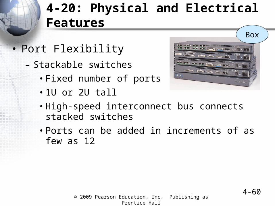
4-20: Physical and Electrical Features
• Port Flexibility
– Stackable switches
• Fixed number of ports
• 1U or 2U tall
• High-speed interconnect bus connects stacked switches
• Ports can be added in increments of as few as 12
Box

© 2009 Pearson Education, Inc. Publishing as Prentice Hall4-61
4-20: Physical and Electrical Features
• Port Flexibility
– Modular switches
• 1U or 2U tall
• Contain one or a few slots
• Each slot module contains 1 to 4 ports
Module
Box

© 2009 Pearson Education, Inc. Publishing as Prentice Hall 4-62
4-20: Physical and Electrical Features
• Port Flexibility
– Chassis switches
• Several U tall
• Contain several expansion slots
• Each expansion board contains several slots
• Most core switches are chassis switches
Box

© 2009 Pearson Education, Inc. Publishing as Prentice Hall4-63
4-20: Physical and Electrical Features
• Uplink Ports
– Normal Ethernet RJ-45 switch ports transmit on Pins 3 and 6 and listen on Pins 1 and 2
• If you connect two normal switch ports on different switches via UTP cords, the ports will not be able to communicate
• A crossover cable solves this problem
NormalSwitch
Port
NormalSwitch PortOn Parent
SwitchPins3 & 6
Pins1 & 2
CrossoverCable
Pins1 & 2
Pins3 & 6
Box

© 2009 Pearson Education, Inc. Publishing as Prentice Hall4-64
4-20: Physical and Electrical Features
• Uplink Ports
– Most switches have at least one uplink port, which transmits on Pins 1 and 2. You can use an ordinary UTP cord to connect a UTP uplink port on one switch to any normal port on a parent switch
– Today, most switches have ports that automatically turn into uplink ports when they detect a switch at the end of the link
Box

© 2009 Pearson Education, Inc. Publishing as Prentice Hall4-65
4-20: Physical and Electrical Features
• Electrical Power
– Switches require electrical power
– In addition, switches can provide electrical power to devices connected by UTP
– With Power over Ethernet (POE), switches can supply power to devices connected by UTP
Box
Data and Power
UTP

© 2009 Pearson Education, Inc. Publishing as Prentice Hall4-66
4-20: Physical and Electrical Features
• Electrical Power
– Why is POE important?
• Installing devices like access points require a free electrical plug to be nearby
• A free plug often is not available, and bringing power can be expensive
– Under the original 802.3af POE standard
• Provide up to 13 watts to attached devices
• Sufficient for simple wireless access points
• Sufficient for VoIP phones
Box

© 2009 Pearson Education, Inc. Publishing as Prentice Hall4-67
4-20: Physical and Electrical Features
• Electrical Power
– Now, the 802.3at POE plus is under development
• 30 or 60 watts
• Backwardly compatible with 802.3af
• Sufficient for multiband wireless access points (see Chapter 5)
• Sufficient for other small devices such as VoIP telephones
• Still not sufficient for PCs
Box

© 2009 Pearson Education, Inc. Publishing as Prentice Hall4-68
4-20: Physical and Electrical Features
• Electrical Power
– New switches can be purchased with POE and POE plus
• Can also add equipment to an existing switch
– Automatically sense device compliance
• So will not try to send power to a device that cannot use it or may be harmed by it
– Providing power can raise heat in wiring/switching rooms and switch rooms
Box

© 2009 Pearson Education, Inc. Publishing as Prentice Hall 4-69
Ethernet Security

© 2009 Pearson Education, Inc. Publishing as Prentice Hall 4-70
4-21: 802.1X Ethernet Port-Based Access Control
Danger: An attacker will walk in and plug into a wall jackThis bypasses the border firewall
Solution: Authenticate everyone who connects to an access switch802.1X standardizes this authentication

© 2009 Pearson Education, Inc. Publishing as Prentice Hall 4-71
4-21: 802.1X Ethernet Port-Based Access Control
Client PC is called the supplicantIt sends credentials (proof of identity) to the switch
The switch is called the network access serverThe NAS sends the credentials onto a central authentication server
CredentialsCredentials

© 2009 Pearson Education, Inc. Publishing as Prentice Hall4-72
4-21: 802.1X Ethernet Port-Based Access Control
Authentication server usually is a RADIUS serverAuthentication server checks credentials
against its authentication database
Credentials

© 2009 Pearson Education, Inc. Publishing as Prentice Hall4-73
4-21: 802.1X Ethernet Port-Based Access Control
Credentials
Centralizing credential checking brings consistencyNo matter what switch the computer plugs into,
It will be authenticated with the same credentials databaseAlso, this database can be updated instantly if needed

© 2009 Pearson Education, Inc. Publishing as Prentice Hall4-74
4-21: 802.1X Ethernet Port-Based Access Control
RADIUS server sends accept or reject message to NASSwitch accepts or rejects the supplicant client
Accept/RejectAccept/
Reject

© 2009 Pearson Education, Inc. Publishing as Prentice Hall4-75
4-22: Media Access Control (MAC) Security (802.1AE)
• 802.1X prevents unauthorized hosts from connecting to a switch
• However, once hosts are admitted to the network, they can send false supervisory frames to switches
– This allows them to reroute frames to the wrong destination, stop forwarding frames, etc.
– The 802.1AE standard requires the sender of a supervisory frame to authenticate itself to the switch to which it sends the supervisory frame

© 2009 Pearson Education, Inc. Publishing as Prentice Hall4-76
4-22: MAC Security (802.1AE)
The message is encrypted with a key that only the sending and receiving switches know
This authenticates the sender to the receiver because only the authentic sender would know the shared key
Encryption and decryption are done by each pair of switches along the way

© 2009 Pearson Education, Inc. Publishing as Prentice Hall4-77
4-22: MAC Security (802.1AE)
Here, the attacker spoofs a switch and creates an attack frame
It sends he illegitimate supervisory frame to Switch A
Switch A cannot decrypt the frame because the attacker did not know the correct key for encrypting it
Switch A drops the frame
The attack cannot go on to Switch B

© 2009 Pearson Education, Inc. Publishing as Prentice Hall 4-78
Routed LANs
Not all LANs are switched networks
Some are routed networks (especially large LANs)

© 2009 Pearson Education, Inc. Publishing as Prentice Hall4-79
4-23: Routed LAN with Ethernet Subnets
When a routed LAN links multipleEthernet switched networks,individual switched networks are called subnets
© 2009 Pearson Education, Inc. Publishing as Prentice Hall 4-80
Topics Covered

© 2009 Pearson Education, Inc. Publishing as Prentice Hall4-81
Topics Covered
• Ethernet MAC Layer Standards– Switch operation
• Operation of a hierarchy of switches
– Single possible path between any two computers– Hierarchy gives low price per frame transmitted– Single points of failure and the Spanning Tree
Protocol
• VLANs and frame tagging reduce congestion and add security
• Momentary traffic peaks: addressed by overprovisioning and priority
• Hubs and CSMA/CD (in a box)

© 2009 Pearson Education, Inc. Publishing as Prentice Hall4-82
Topics Covered
• Switch Purchasing Considerations
– Number and speed of ports
– Store-and-forward versus cut-through switches
– Managed switches

© 2009 Pearson Education, Inc. Publishing as Prentice Hall4-83
Topics Covered
• Advanced Switch Purchasing Considerations
– Physical size
– Fixed-Port-Switches
– Stackable Switches
– Modular Switches
– Chassis Switches
– Pins in Switch Ports and Uplink Ports
– Electrical Power (802.3af and 802.3at)• POE and POE Plus
Box

© 2009 Pearson Education, Inc. Publishing as Prentice Hall4-84
Topics Covered
• Ethernet security– 802.1X Port-Based Access Control
• Requires users to authenticate themselves before getting access to the network
– 802.1AE MACsec
• Prevents attackers from sending fake supervisory commands to switches
• Routed LANs are possible
– Individual Ethernet networks in a routed LAN are called subnets

© 2009 Pearson Education, Inc. Publishing as Prentice Hall 4-85
All rights reserved. No part of this publication may be reproduced, stored in a retrieval system, or transmitted, in any form or by any means, electronic,
mechanical, photocopying, recording, or otherwise, without the prior written permission of the publisher. Printed in the United States of America.
Copyright © 2009 Pearson Education, Inc. Copyright © 2009 Pearson Education, Inc. Publishing as Prentice HallPublishing as Prentice Hall