© 2008 snap-on incorporated; all rights reserved
TRANSCRIPT

© 2008 Snap-on Incorporated; All Rights Reserved

2© 2010 Snap-on Incorporated; All Rights Reserved 2
Course Objectives• This module covers:
– Electronic Principles– Electronic Devices– Electronic Measurements– Solid State Devices– Schematic Symbols– Good Info to Know

33
Electronic Basics

44
Electronic BasicsElectricity starts in the atom.

55
Electronic BasicsElectricity is the flow of electrons (-) from one atom to another.

6
1. Electricity is flow of what part of the atom?
Review for Understanding

77
Electronic Basics - FlowDirect current (DC) flows in one direction.
5 volts DC is often used in computer systems
Charging voltage is often about 14.2 Volts DC

88
Electronic Basics - FlowAlternating current (AC) changes direction.
AC voltage needs to be rectified to DCin order to be used by computer systems

99
Electronic Basics - FlowFor discussion purposes, electricity is either conventional flow or electron flow.

1010
Electronic Basics - MaterialsConductors are materials that have less than 4 electrons loosely held in their outer orbit.

1111
Electronic Basics - MaterialsInsulators are materials that have more than 4 electrons tightly held in their outer orbit.

1212
Electronic Basics - MaterialsSemi-Conductors are materials that have exactly 4 electrons in their outer orbit.
Semiconductor materials are thebuilding blocks of electronic components

1313
Electronic Basics - MaterialsSemi-Conductors are materials that have exactly 4 electrons in their outer orbit.
Carbon (C), Silicon (Si), and Germanium (Ge), are the materials used to manufacture resistors, diodes and transistors.

14
1. How are conductors & insulators different?
2. Explain AC & DC.
3. Name 2 materials used to manufacture semiconductor devices.
Review for Understanding

1515
Electronic Basics – MeasurementsAmperage is the unit for measuring the rate of electrical current flow.
Important to know because of transistor current gain factor.

1616
Electronic Basics – MeasurementsVoltage is the electrical pressure or force that causes electrons to flow.
Important to know because of diode forward bias voltage drop

1717
Electronic Basics – Measurements Resistance to flow is measured in Ohms and abbreviated with the Greek letter Omega. Ω
Important to know because resistance causes heat.

1818
Electronic BasicsSemiconductors are materials with exactly 4 electrons in their “valence rings”. They can change function and become either conductors or insulators.
Add an electron = 5 Subtract an electron = 3
Semiconductor materials are used to build “solid state” devices.

1919
Electronic BasicsSemiconductors are used to build “solid state” devices.
Solid state devices control electrical flow without any moving parts!

2020
Electronic BasicsSemi-conductors carry current w/o losing electrons through the concept of hole flow. Holes in a P-type material, being positively charged, attract electrons causing movement.
21
1. What is the unit of measure for electromotive force?
2. What is the unit of measure for current flow
3. What is the unit of measure for resistance to flow?
4. What is the general meaning of the term “solid state”?
Review for Understanding
2222
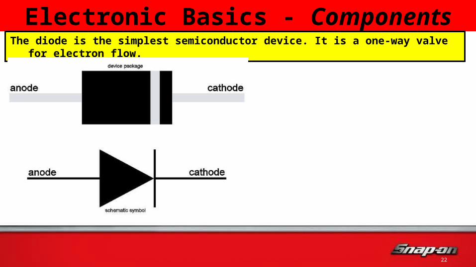
Electronic Basics - ComponentsThe diode is the simplest semiconductor device. It is a one-way valve for electron flow.
2323
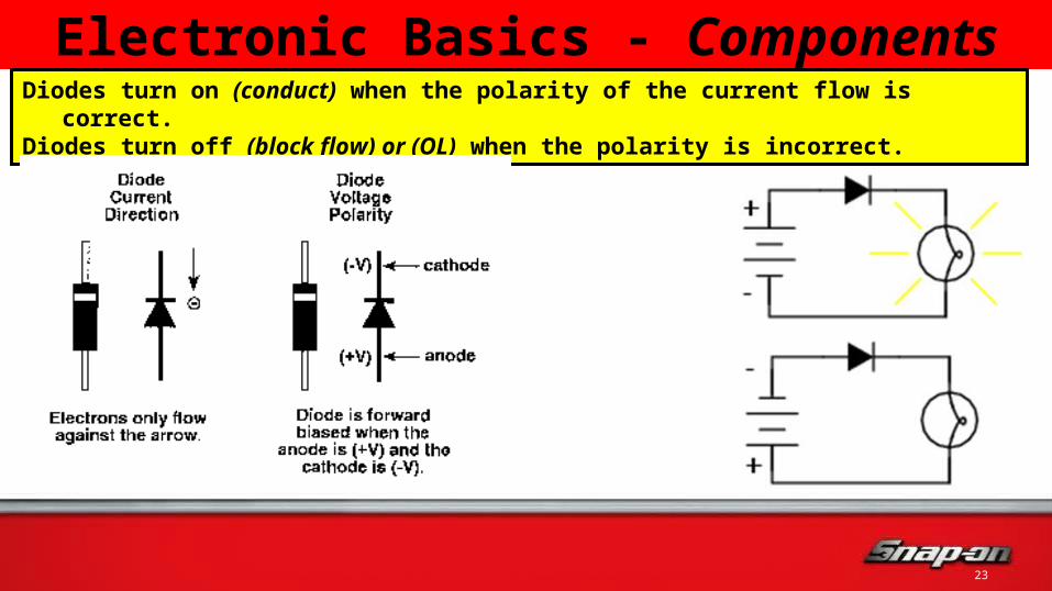
Electronic Basics - ComponentsDiodes turn on (conduct) when the polarity of the current flow is correct.Diodes turn off (block flow) or (OL) when the polarity is incorrect.
2424
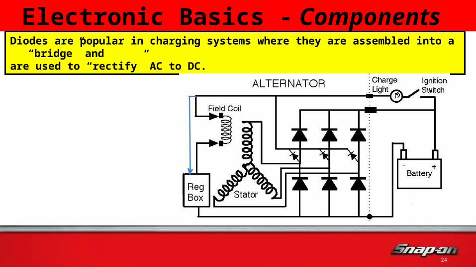
Electronic Basics - Components Diodes are popular in charging systems where they are assembled into a “bridge” andare used to “rectify” AC to DC.

2525
Electronic Basics - ComponentsA single diode can do half-wave rectification of AC to DC.
Multiple diodes assembled In a bridge can do full-waveAC to DC rectification

2626
Electronic Basics - ComponentsThe diode contains a P - N junction. (P = positive & N = negative) A diode conducting electricity is said to be forward biased and will typically have a voltage drop of .4 to .7 volts when tested with a DMM
Semiconductor testing should alwaysbe done using a digital multi-meter.

2727
Electronic Basics - ComponentsA diode that is blocking or not allowing flow is said to be reverse biased. A reverse biased diode reads OL when checked with the diode test mode of a DMM.
OL.4 to .7Voltage
Drop

2828
Electronic Basics - ComponentsA diode reading zero in both directions is shorted & conducts all the time.An open diode reads OL both ways & never conducts at all.
0.0 0.0 0L 0L
OpenShorted

2929
Electronic Basics - ComponentsLight Emitting Diodes have a higher forward bias voltage drop then regular diodes.
LED’s illuminate when forward biased.They do not illuminate when blocking.
3030
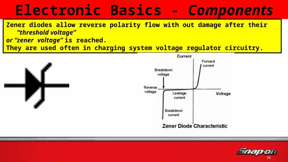
Electronic Basics - ComponentsZener diodes allow reverse polarity flow with out damage after their “threshold voltage” or “zener voltage” is reached. They are used often in charging system voltage regulator circuitry.

3131
Electronic Basics - ComponentsClamping diodes are regular diodes connected in parallel across coils of wire to preventcomponent damage from induced voltage spikes returning to the PCM and other electronic components as the coil circuits are opened.
AC Clutches, relays, & vacuum switchingsolenoids all need clamping diodes.

32
1. What is the main purpose of a diode?
2. Explain diode forward bias.
3. Explain diode reverse bias.
4. How does a zener diode differ from a regular diode?
5. How is a diode connected to act as a voltage spike clamp?
6. What is the best type of meter to use for diode testing?
Review for Understanding

3333
Electronic Basics - ComponentsThe transistor is a solid-state switching device.

3434
Electronic Basics - ComponentsThe transistor has legs labeled E, B, and C.

3535
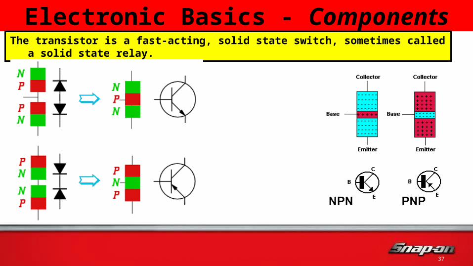
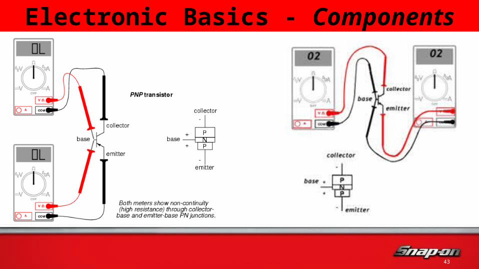
Electronic Basics - Components A transistor can be considered as two P-N junctions placed back to back. One of these, namely the base emitter junction is forward biased, while the other, the base collector junction is reverse biased.
3636
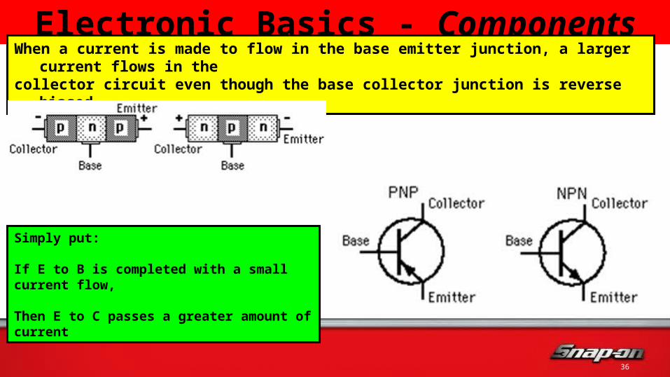
Electronic Basics - ComponentsWhen a current is made to flow in the base emitter junction, a larger current flows in the collector circuit even though the base collector junction is reverse biased.
Simply put:
If E to B is completed with a small current flow, Then E to C passes a greater amount of current
3737
Electronic Basics - ComponentsThe transistor is a fast-acting, solid state switch, sometimes called a solid state relay.
3838
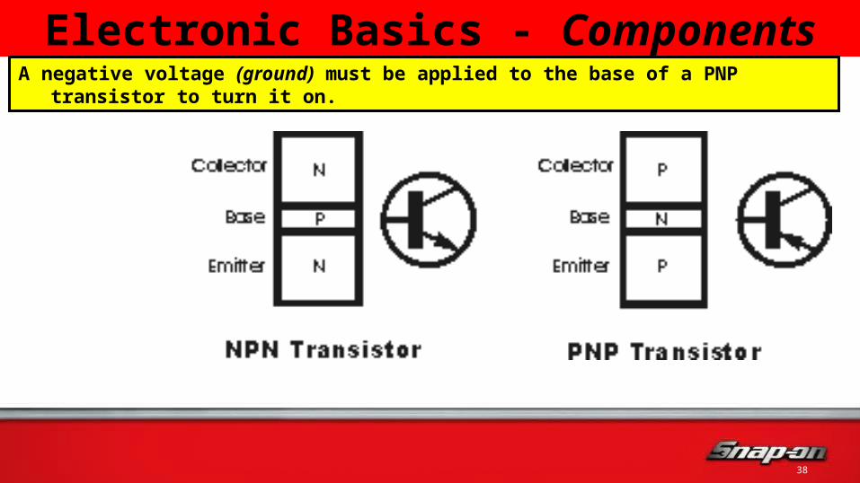
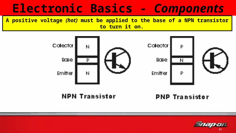
Electronic Basics - ComponentsA negative voltage (ground) must be applied to the base of a PNP transistor to turn it on.
3939
Electronic Basics - ComponentsA positive voltage (hot) must be applied to the base of a NPN transistor to turn it on.

4040
Electronic Basics - ComponentsTransistors carry current without losing electrons through the concept of hole flow.

4141
Electronic Basics - ComponentsIn a relay, if 85 to 86 is energized, then the contacts between 30 & 87 close.
In a transistor, if E to B is completed, then E to C closes.

4242
Electronic Basics - ComponentsIn a relay, small current through 85 & 86 can switch a larger current through 30 & 87.
In a transistor, small base current can switch a larger collector current.
4343
Electronic Basics - Components

44
1. What is the main purpose of a transistor?
2. Using If : Then, explain transistor operation.
3. When does a PNP transistor switch on & conduct?
4. When does a NPN transistor switch on & conduct?
5. Why might a transistor be called a solid state relay?
Review for Understanding

4545
Electronic Basics - ComponentsCapacitors can store an electrical charge for a short period of time
They are used as back-up power supplies in automotive air bag systems

4646
Electronic Basics - ComponentsA resistor offers an opposition to electromotive force in a circuit.
Carbon CompositionResistors

4747
Electronic Basics - ComponentsResistor values can be determined by using a color code chart.

4848
Electronic Basics - ComponentsA thermistor is used to provide compensating voltage in components or act as atemperature sensor as in an IAT or an ECT. They may be NTC or PTC in design.

49
1. What is the basic purpose of a resistor?
2. What is the basic purpose of a capacitor?
3. Thermistors can be used as what engine control sensors?
Review for Understanding

5050
Electronic Basics – Good to Know An Integrated Circuit (IC or chip) is a large # of diodes, transistors, resistors, capacitors, mounted to a semiconductor material used to make logic decisions & commands.

5151
Electronic Basics – Good to KnowA microprocessor is a small version of a computer. PCM or any ECU/CPU
5252
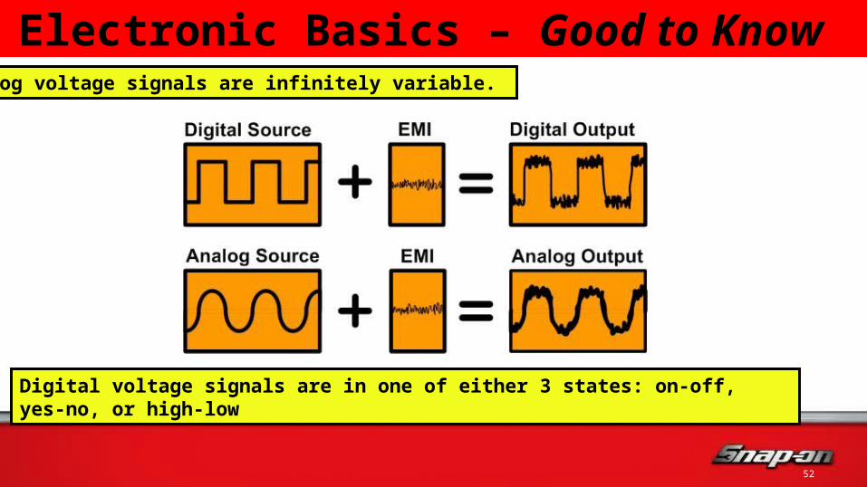
Electronic Basics – Good to Know Analog voltage signals are infinitely variable.
Digital voltage signals are in one of either 3 states: on-off, yes-no, or high-low

5353
Electronic Basics – Good to KnowSince computers can only read digital, binary voltage signals, analog signals must go though an analog/digital (A/D) converterin order to be used or “understood” by the computer.

5454
Electronic Basics – Good to KnowFrequency is a term that describes how often a signal performs a complete cycle.

5555
Electronic Basics – Good to KnowA cycle is a description of the changes that a signal goes through without repeating.

5656
Electronic Basics – Good to KnowFrequency is measured in Hertz. Hertz is a measurement of Cycles per Second.

57
1. Describe a digital wave.
2. Describe an analog wave.
3. Which axis is voltage on a waveform diagram?
4. Which axis is time on a waveform diagram?
Review for Understanding

5858
Electronic Basics - Schematics
Ground Battery Fuse Circuit Breaker

5959
Electronic Basics - Schematics
Wire Wires Crossing Wire Connector Wire Splice
6060
Electronic Basics - Schematics
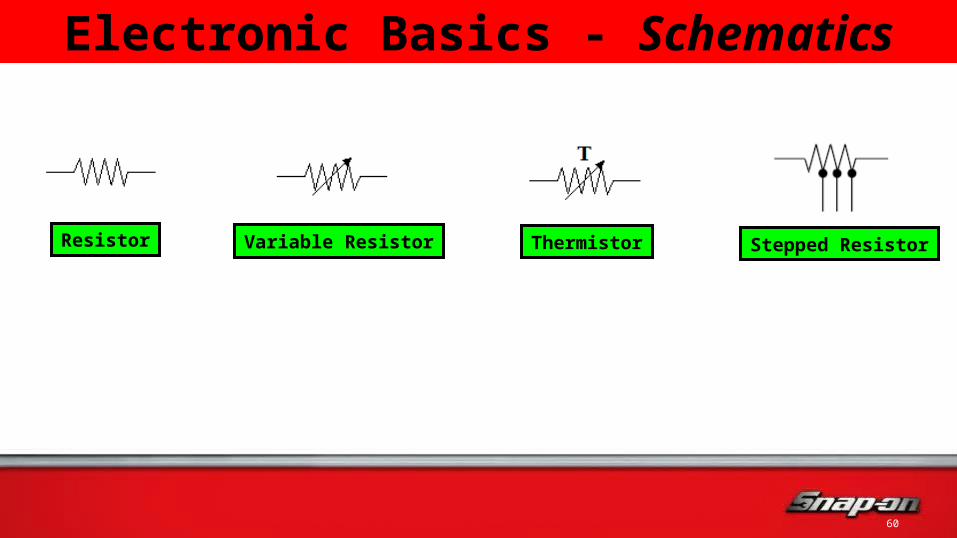
Resistor Variable Resistor Thermistor Stepped Resistor

6161
Electronic Basics - Schematics
Diode Zener Diode Light Emitting Diode Rectifier Bridge
6262
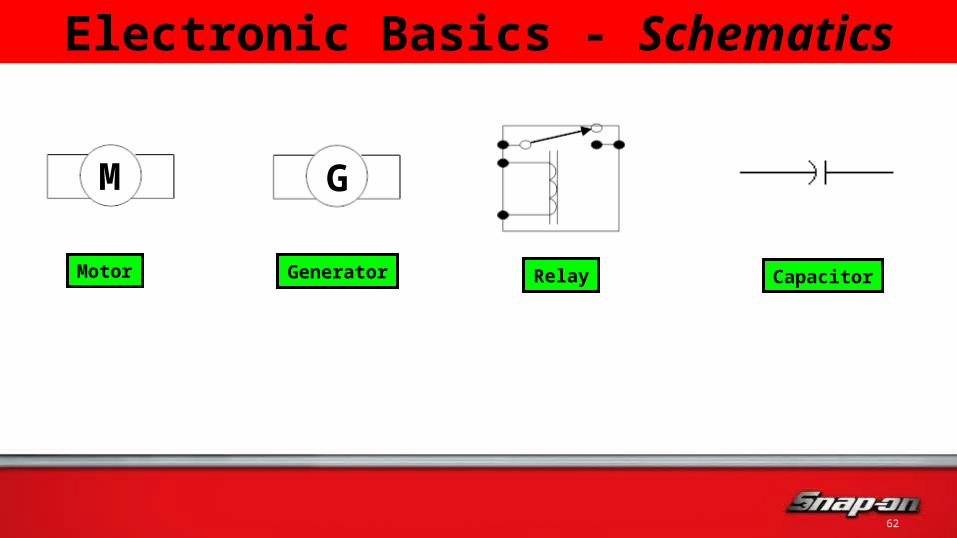
Electronic Basics - Schematics
M G
Motor Generator Relay Capacitor

6363
Electronic Basics - Schematics
Twisted Pair of Wires Switch Momentary Switch Contacts
6464
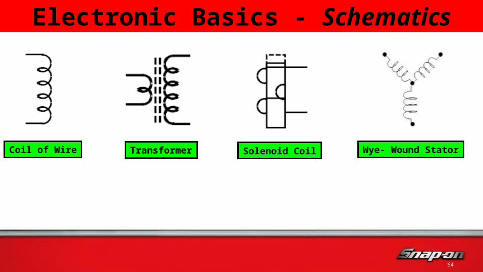
Electronic Basics - Schematics
Coil of Wire Transformer Solenoid Coil Wye- Wound Stator

6565
Electronic Basics - Schematics
PNP Transistor NPN Transistor Bulb Horn

66
1. What are schematic symbols?
2. Why are schematic symbols used?
3. Can you name the symbols on the following slide without help?
Review for Understanding

6767
Electronic Basics - Schematics

6868
Electronic Basics - Schematics

6969
Electronic Basics - Schematics

7070
Electronic Basics - Schematics
71
End of BASIC
ELECTRONIC Training