- training.bitzerpv.com · 2 general safety references: ... 21 jawa barat - indonesia 22 st. marys...
TRANSCRIPT

www.bitzerus.com 1
2 www.bitzerus.com
General safety references: Warning! The compressor is under pressure with a holding charge of 14 psi above atmospheric pressure. Incorrect handling may cause injury to skin and eyes. Wear safety goggles while working on compressor. Do not open connections before pressure has been released. Caution! During operation, surface temperatures exceeding 140°F or below 32°F can be reached. Serious burnings possible. Lock and mark accessible sectors. Before working on the compressor: Switch off and let cool down. Warning! If working on the compressor after the plant has been commissioned: Compressor is under pressure! In case of improper handling serious injuries are possible. Release the pressure in the compressor! Wear safety goggles!
The intention of this document is to serve as general guidelines. The information contained is not intended to replace specific equipment and/or system manufacturer's information or guidelines. BITZER im-plies no liability for the information contained. It is BITZER's implicit intention that nothing contained in this guide replaces any past, pre-
sent or future warranty policy of BITZER and/or any other manufactur-er's equipment
These guidelines are not a replacement for information specific to that of the manufacturer or the manufacturer's system technical product
information.
Each system may vary in design, usage and specifications. This docu-ment is intended for use specific to the compressor only and not in-
tended to be a "catch all" for any and every possible application of the compressor.
BITZER's intention is that only qualified and certified (where applicable) individuals specific to the refrigeration industry use the information
contained and all standard refrigeration handling and safety practices must be followed at all times.
BITZER's intention is that all electric work is performed by qualified and certified (where applicable) individuals and all standard electrical safety
practices must be followed at all times.
www.bitzerus.com 3
CONTENTS
1 General Information Page 1.1 Contact Information 4 1.2 ECOLINE Nomenclature 5 1.3 Serial Number Explanation 6 1.4 Quick Ship Program 7 1.5 Core Charge Return 8 1.6 Technical Support 9 1.7 ECOLINE vs Standard model 10
2 Compressor Data 2.1 CE1, CE2, CE3 Technical Data 12 2.2 CE4 Technical Data 13 2.3 BE5, BE6 Technical Data 14 2.4 2-Stage Technical Data 15 2.5 Dimensional Drawings & Connections 16 2.6 Application Limits 36 2.7 Operating Parameters 47
3 Electrical Information 3.1 Maximum Operating Amps and Max MCC 48 3.2 Operating Amps 55 3.3 UL Motor Codes 59 3.4 Wiring diagrams/Power Connection 60
4 Accessories / Options 4.1 Protection Devices (SE-B3, Delta PII, OLCK1) 64 4.2 Other Oil Monitoring Devices 71 4.3 Refrigeration Oils 72 4.4 Capacity Regulation 76
5 Spare Parts 5.1 Service Parts Changes 78 5.2 Mounting Kits 79 5.3 Service Parts 80 5.4 Crankcase Heater and Head Fan 82
6 Preventive Maintenance / Service 6.1 Operating Temperatures & Oil Guidelines 83 6.2 Switching Frequency and Vibrations 84 6.3 Tightening Torques 85 6.4 Common Wrench Sizes for Basic Service 86 6.5 Valve plate replacement instructions 87 6.6 Trouble Shooting 88
7 Technical Documentation 90 8 System Parameters 92

4 www.bitzerus.com
BITZER US, Inc 4080 Enterprise Way Flowery Branch, GA 30542 Phone: 770-503-9226 Fax: 770-503-9440 www.bitzerus.com Email: [email protected]
24hr Quick Ship Emergency Replacement Hotline for US Customers:
1-888-GO BITZER (1-888-462-4893)
BITZER Canada Inc. 21125 Daoust Street Sainte-Anne-De-Bellevue, QC, H9X 0A3 Canada Phone: 514-697-3363 Fax: 514-697-9768
www.bitzer.ca
BITZER México S de RL de CV Av. Adolfo López Mateos 221 Bodega 9 Col. Victoria Guadalupe, N.L., 67110, México
Phone: +52 (81) 1522 4500 Fax: +52 (81) 1522 4505
www.bitzermexico.com
BITZER US – Latinamerica Phone +1 770 718 2914 [email protected] [email protected] [email protected] [email protected] [email protected] [email protected]
1 General Information
www.bitzerus.com 5
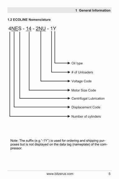
1.2 ECOLINE Nomenclature
1 General Information
4NES - 14 - 2NU - 1Y
Number of cylinders
Displacement Code
Centrifugal Lubrication
Motor Size Code
Voltage Code
# of Unloaders
Oil type
Note: The suffix (e.g.“-1Y”) is used for ordering and shipping pur-poses but is not displayed on the data tag (nameplate) of the com-pressor.
6 www.bitzerus.com
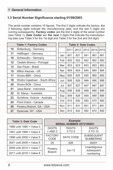
1.3 Serial Number Significance starting 01/09/2003
The serial number contains 10 figures. The first 2 digits indicate the factory, the 3 following digits indicate the manufacturing date, and the last 5 digits are running subsequently. Factory codes are the first 2 digits of the serial number (see Table 1). Date Codes are the next 3 digits that indicate the manufactur-ing date (use Table 3 for the 1st digit and Table 2 for the 2nd and 3rd digit).
1 General Information
Example:
SERIAL NUMBER 2572100001
DIGITS 1 AND 2
DIGITS 3 TO 5
DIGITS 5 TO 10
FACTORY CODE
DATE CODE SUBSEQUENT NUMBERING
25 826 00001
Flowery Branch
Jun-12 Unambiguous subsequent
numbering
Table 3: Date Code
1986 until 1990 = Value 3
1991 until 1995 = Value 4
1996 until 2000 = Value 5
2001 until 2005 = Value 6
2006 until 2010 = Value 7
2011 until 2016 = Value 8
Table 1: Factory Codes
10 Rottenburg - Germany
11 Hailfingen - Germany
16 Schkeuditz - Germany
12 Castelo Branco - Portugal
13 Sao Paulo - Brazil
15 Milton Keynes - UK
17 Works BBR - China
18 Works Capetown - South Africa
20 Works BCB - China
21 Jawa Barat - Indonesia
22 St. Marys - Austrialia
23 Sunshine, Victoria - Australia
24 Point Claire - Canada
25 Flowery Branch, GA - USA
27 Syracuse, NY - USA
Table 2: Date Codes
2011 2012 2013 2014 2015
Jan 801 821 841 861 881
Feb 802 822 842 862 882
Mar 803 823 843 863 883
Apr 804 824 844 864 884
May 805 825 845 865 885
Jun 806 826 846 866 886
Jul 807 827 847 867 887
Aug 808 828 848 868 888
Sep 809 829 849 869 889
Oct 810 830 850 870 890
Nov 811 831 851 871 891
Dec 812 832 852 872 892

www.bitzerus.com 7
1.4 BITZER Quick Ship Program
Placing your Order:
Call 770-503-9226 M-F from 8am - 5pm
Call 1-888-GO BITZER (1-888-462-4893)
Choose from 4 Shipping Options:
Next Day Delivery
Second Day Delivery
Standard Ground Transportation
Customer Pick-Up
Please provide the following information to our Customer Service Associates:
Failed Model Number
Serial Number
Contact Name
Contact Phone Number
Email Address
Ship to Address
Is a liftgate needed?
Credit Card Number
(American Express / Visa / Mastercard)
1 General Information
8 www.bitzerus.com
Contact customer service at 770-503-9226 or email [email protected] for a RMA form. Please Note: A credit card number (or a PO if you have a BITZER account) is re-quired for the replacement compressor and core deposit. We will call you back with a delivery confirmation ASAP. Once a Return Material Authorization (RMA) form is filled out, we will also arrange to have your failed compressor picked up. BITZER will pay the freight back to the factory and, as soon as it arrives at the Atlanta area plant, we will issue you a credit against your core depos-it. BITZER does not charge a core charge for your replacement com-pressor if you adhere to the following procedures: 1. After receiving your replacement compressor, you have 2 weeks
to contact us to schedule the pick up of your core. If you fail to do so BITZER will execute the core charge on your current PO.
2. The compressor should be shipped fully sealed: Use blank offs
or the service valves shipped with replacement compressor. 3. Attach Return Material Authorization form to the compressor.
Your RMA form will be issued when placing your order.
1.5 BITZER Core Charge Return Policy
1 General Information
www.bitzerus.com 9
If there has been more than one failure in a system, speak to an application engineer: Contact technical support at 770-503-9226 or email [email protected] Please provide as much of the following information as possible:
Model number
Serial number
Refrigerant
Voltage
Evaporating SST or Pressure
Condensing SDT or Pressure
Return Gas Temperature
Liquid Subcooling / Liquid Temperature
Discharge gas temperature
Amp draw
Oil pressure
See back page for system parameter.
1.6 Technical Support
1 General Information
10 www.bitzerus.com
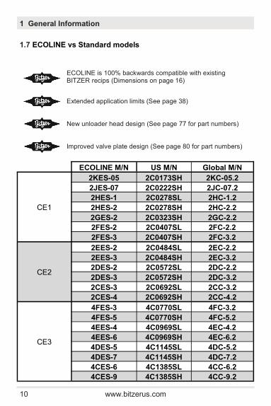
1.7 ECOLINE vs Standard models
1 General Information
ECOLINE is 100% backwards compatible with existing BITZER recips (Dimensions on page 16)
Extended application limits (See page 38)
New unloader head design (See page 77 for part numbers)
Improved valve plate design (See page 80 for part numbers)
ECOLINE M/N US M/N Global M/N
CE1
2KES-05 2C0173SH 2KC-05.2
2JES-07 2C0222SH 2JC-07.2
2HES-1 2C0278SL 2HC-1.2
2HES-2 2C0278SH 2HC-2.2
2GES-2 2C0323SH 2GC-2.2
2FES-2 2C0407SL 2FC-2.2
2FES-3 2C0407SH 2FC-3.2
CE2
2EES-2 2C0484SL 2EC-2.2
2EES-3 2C0484SH 2EC-3.2
2DES-2 2C0572SL 2DC-2.2
2DES-3 2C0572SH 2DC-3.2
2CES-3 2C0692SL 2CC-3.2
2CES-4 2C0692SH 2CC-4.2
CE3
4FES-3 4C0770SL 4FC-3.2
4FES-5 4C0770SH 4FC-5.2
4EES-4 4C0969SL 4EC-4.2
4EES-6 4C0969SH 4EC-6.2
4DES-5 4C1145SL 4DC-5.2
4DES-7 4C1145SH 4DC-7.2
4CES-6 4C1385SL 4CC-6.2
4CES-9 4C1385SH 4CC-9.2

www.bitzerus.com 11
1 General Information
ECOLINE M/N US M/N Global M/N
CE4
4VE-7 4C1480PL 4VC-6.2
4VE-10 4C1480PH 4VC-10.2
4VES-7 4C1480SL 4VCS-6.2
4VES-10 4C1480SH 4VCS-10.2
4TE-9 4C1761PL 4TC-8.2
4TE-12 4C1761PH 4TC-12.2
4TES-9 4C1761SL 4TCS-8.2
4TES-12 4C1761SH 4TCS-12.2
4PE-12 4C2067PL 4PC-10.2
4PE-15 4C2067PH 4PC-15.2
4PES-12 4C2067SL 4PCS-10.2
4PES-15 4C2067SH 4PCS-15.2
4NE-14 4C2397PL 4NC-12.2
4NE-20 4C2397PH 4NC-20.2
4NES-14 4C2397SL 4NCS-12.2
4NES-20 4C2397SH 4NCS-20.2
BE5
4JE-15 4B2707PL 4J-13.2
4JE-22 4B2707PH 4J-22.2
4HE-18 4B3139PL 4H-15.2
4HE-25 4B3139PH 4H-25.2
4GE-23 4B3604PL 4G-20.2
4GE-30 4B3604PH 4G-30.2
4FE-28
4FE-35
BE6
6JE-25 6B4060PL 6J-22.2
6JE-33 6B4060PH 6J-33.2
6HE-28 6B4709PL 6H-25.2
6HE-35 6B4709PH 6H-35.2
6GE-34 6B5406PL 6G-30.2
6GE-40 6B5406PH 6G-40.2
6FE-44 6B6462PL 6F-40.2
6FE-50 6B6462PH 6F-50.2
12 www.bitzerus.com
2 Compressor Data 2
.1
CE
1, C
E2, C
E3 T
ech
nic
al D
ata
T
ub
e C
on
necti
on
s
Seri
es
Eco
lin
e
Mo
del
Nu
mb
er
Mo
tor
CF
M
CF
H
CR
Read
y
Sin
gle
P
hase
Op
tio
n
Du
al
Vo
ltag
e
230/4
60
Oil
Ch
arg
e
(oz)
Weig
ht
(lb
s)
DL
(in
.)
SL
(in
.)
CE
1
2K
ES
-05
1
2.9
173
--
Yes
--
35
95
1/2
5/8
CE
1
2JE
S-0
7
1
3.7
222
--
Yes
--
35
95
1/2
5/8
CE
1
2H
ES
-1
2
4.6
278
--
Yes
--
35
97
1/2
5/8
CE
1
2H
ES
-2
1
4.6
278
--
Yes
--
35
99
1/2
5/8
CE
1
2G
ES
-2
1
5.4
323
--
Yes
--
35
99
1/2
5/8
CE
1
2F
ES
-2
2
6.8
407
--
Yes
--
35
99
1/2
5/8
CE
1
2F
ES
-3
1
6.8
407
--
--
--
35
103
1/2
5/8
CE
2
2E
ES
-2
2
8.1
486
--
--
--
53
150
5/8
7/8
CE
2
2E
ES
-3
1
8.1
486
--
Yes
--
53
157
5/8
7/8
CE
2
2D
ES
-2
2
9.5
571
--
--
--
53
150
5/8
7/8
CE
2
2D
ES
-3
1
9.5
571
--
Yes
--
53
157
5/8
7/8
CE
2
2C
ES
-3
2
11.5
691
--
Yes
--
53
154
5/8
7/8
CE
2
2C
ES
-4
1
11.5
691
--
--
--
53
154
5/8
7/8
CE
3
4F
ES
-3
2
12.8
772
10%
- 1
00%
--
--
70
181
5/8
7/8
CE
3
4F
ES
-5
1
12.8
772
10%
- 1
00%
--
--
70
190
5/8
7/8
CE
3
4E
ES
-4
2
16.2
968
10%
- 1
00%
--
--
70
185
5/8
1 1
/8
CE
3
4E
ES
-6
1
16.2
968
10%
- 1
00%
--
--
70
190
5/8
1 1
/8
CE
3
4D
ES
-5
2
19.1
1142
10%
- 1
00%
--
--
70
190
7/8
1 1
/8
CE
3
4D
ES
-7
1
19.1
1142
10%
- 1
00%
--
--
70
196
7/8
1 1
/8
CE
3
4C
ES
-6
2
23.1
1385
10%
- 1
00%
--
--
70
201
7/8
1 1
/8
CE
3
4C
ES
-9
1
23.1
1385
10%
- 1
00%
--
--
70
201
7/8
1 1
/8
www.bitzerus.com 13
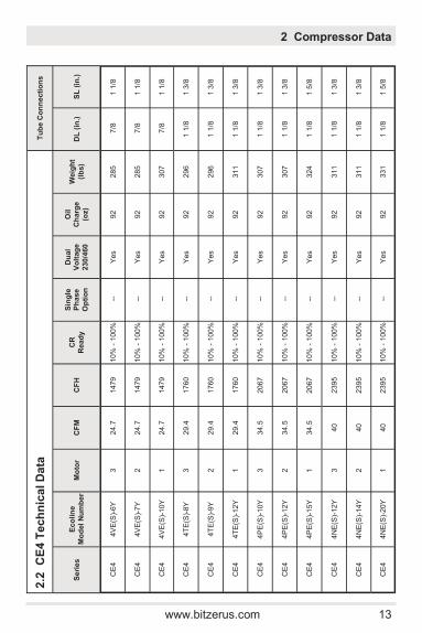
2
.2
CE
4 T
ech
nic
al D
ata
Tu
be C
on
necti
on
s
Seri
es
Eco
lin
e
Mo
del
Nu
mb
er
Mo
tor
CF
M
CF
H
CR
Read
y
Sin
gle
P
hase
Op
tio
n
Du
al
Vo
ltag
e
230/4
60
Oil
Ch
arg
e
(oz)
Weig
ht
(lb
s)
DL
(in
.)
SL
(in
.)
CE
4
4V
E(S
)-6Y
3
24.7
1479
10%
- 1
00%
--
Yes
92
285
7
/8
1 1
/8
CE
4
4V
E(S
)-7Y
2
24.7
1479
10%
- 1
00%
--
Yes
92
285
7
/8
1 1
/8
CE
4
4V
E(S
)-10Y
1
24.7
1479
10%
- 1
00%
--
Yes
92
307
7
/8
1 1
/8
CE
4
4T
E(S
)-8Y
3
29.4
1760
10%
- 1
00%
--
Yes
92
296
1 1
/8
1 3
/8
CE
4
4T
E(S
)-9Y
2
29.4
1760
10%
- 1
00%
--
Yes
92
296
1 1
/8
1 3
/8
CE
4
4T
E(S
)-12Y
1
29.4
1760
10%
- 1
00%
--
Yes
92
311
1 1
/8
1 3
/8
CE
4
4P
E(S
)-10Y
3
34.5
2067
10%
- 1
00%
--
Yes
92
307
1 1
/8
1 3
/8
CE
4
4P
E(S
)-12Y
2
34.5
2067
10%
- 1
00%
--
Yes
92
307
1 1
/8
1 3
/8
CE
4
4P
E(S
)-15Y
1
34.5
2067
10%
- 1
00%
--
Yes
92
324
1 1
/8
1 5
/8
CE
4
4N
E(S
)-12Y
3
40
2395
10%
- 1
00%
--
Yes
92
311
1 1
/8
1 3
/8
CE
4
4N
E(S
)-14Y
2
40
2395
10%
- 1
00%
--
Yes
92
311
1 1
/8
1 3
/8
CE
4
4N
E(S
)-20Y
1
40
2395
10%
- 1
00%
--
Yes
92
331
1 1
/8
1 5
/8
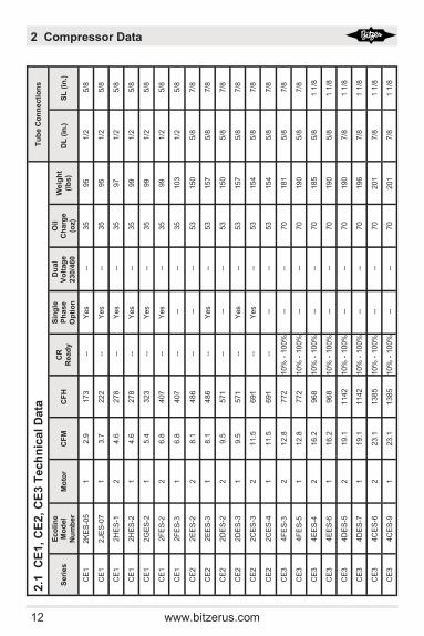
2 Compressor Data
14 www.bitzerus.com
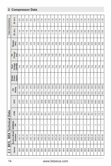
2.3
B
E5, B
E6 T
ech
nic
al
Data
T
ub
e C
on
necti
on
s
Seri
es
Eco
lin
e M
od
el
Nu
mb
er
NO
MIN
AL
HP
C
FM
C
FH
C
R
Read
y
Sin
gle
P
hase
Op
tio
n
Du
al
Vo
ltag
e
230/4
60
Oil
Ch
arg
e
(oz)
Weig
ht
(lb
s)
DL
(in
.)
SL
(in
.)
BE
5
4JE
-13
3
45.1
2707
10%
- 1
00%
--
Yes
141
395
1 1
/8
1 5
/8
BE
5
4JE
-15
2
45.1
2707
10%
- 1
00%
--
Yes
141
419
1 1
/8
1 5
/8
BE
5
4JE
-22
1
45.1
2707
10%
- 1
00%
--
Yes
141
419
1 1
/8
1 5
/8
BE
5
4H
E-1
5
3
52.3
3141
10%
- 1
00%
--
Yes
141
404
1 1
/8
1 5
/8
BE
5
4H
E-1
8
2
52.3
3141
10%
- 1
00%
--
Yes
141
419
1 1
/8
1 5
/8
BE
5
4H
E-2
2
1
52.3
3141
10%
- 1
00%
--
Yes
141
428
1 1
/8
2 1
/8
BE
5
4G
E-2
0
3
60.1
3606
10%
- 1
00%
--
Yes
158
423
1 1
/8
2 1
/8
BE
5
4G
E-2
3
2
60.1
3606
10%
- 1
00%
--
Yes
158
423
1 1
/8
2 1
/8
BE
5
4G
E-3
0
1
60.1
3606
10%
- 1
00%
--
Yes
158
454
1 1
/8
2 1
/8
BE
5
4F
E-2
5
3
72.3
4339
10%
- 1
00%
--
Yes
158
432
1 1
/8
2 1
/8
BE
5
4F
E-2
8
2
72.3
4339
10%
- 1
00%
--
Yes
158
456
1 1
/8
2 1
/8
BE
5
4F
E-3
5
1
72.3
4339
10%
- 1
00%
--
Yes
158
456
1 1
/8
2 1
/8
BE
6
6JE
-22
3
67.7
4062
10%
- 1
00%
--
Yes
167
470
1 3
/8
2 1
/8
BE
6
6JE
-25
2
67.7
4062
10%
- 1
00%
--
Yes
167
503
1 3
/8
2 1
/8
BE
6
6JE
-33
1
67.7
4062
10%
- 1
00%
--
Yes
167
509
1 3
/8
2 1
/8
BE
6
6H
E-2
5
3
78.5
4710
10%
- 1
00%
--
Yes
167
494
1 3
/8
2 1
/8
BE
6
6H
E-2
8
2
78.5
4710
10%
- 1
00%
--
Yes
167
503
1 3
/8
2 1
/8
BE
6
6H
E-3
5
1
78.5
4710
10%
- 1
00%
--
Yes
167
518
1 3
/8
2 1
/8
BE
6
6G
E-3
0
3
90.1
5404
10%
- 1
00%
--
Yes
167
503
1 3
/8
2 1
/8
BE
6
6G
E-3
4
2
90.1
5404
10%
- 1
00%
--
Yes
167
503
1 3
/8
2 1
/8
BE
6
6G
E-4
0
1
90.1
5404
10%
- 1
00%
--
Yes
167
525
1 3
/8
2 1
/8
BE
6
6F
E-4
0
3
107.7
6461
10%
- 1
00%
--
Yes
167
525
1 5
/8
2 1
/8
BE
6
6F
E-4
4
2
107.7
6461
10%
- 1
00%
--
Yes
167
532
1 5
/8
2 1
/8
BE
6
6F
E-5
0
1
107.7
6461
10%
- 1
00%
--
Yes
167
532
1 5
/8
2 1
/8
2 Compressor Data
www.bitzerus.com 15
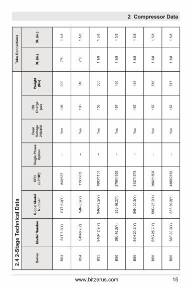
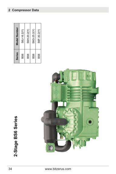
2.4
2-S
tag
e T
ech
nic
al
Data
T
ub
e C
on
necti
on
s
Seri
es
Mo
del
Nu
mb
er
Glo
bal M
od
el
Nu
mb
er
CF
H
(LP
/HP
)
Sin
gle
Ph
ase
Op
tio
n
Du
al
Vo
ltag
e
230/4
60
Oil
Ch
arg
e
(oz)
Weig
ht
(lb
s)
DL
(in
.)
SL
(in
.)
BS
4
S4T
-5.2
(Y)
S4T
-5.2
(Y)
840/5
37
-
- Y
es
106
300
7/8
1 1
/8
BS
4
S4N
-8.2
(Y)
S4N
-8.2
(Y)
1193/7
63
-
- Y
es
106
310
7/8
1 1
/8
BS
5
S4G
-12.2
(Y)
S4G
-12.2
(Y)
1803/1
151
-
- Y
es
158
365
1 1
/8
1 3
/8
BS
6
S6J-1
6.2
(Y)
S6J-1
6.2
(Y)
2706/1
355
-
- Y
es
167
460
1 3
/8
1 5
/8
BS
6
S6H
-20.2
(Y)
S6H
-20.2
(Y)
3137/1
573
-
- Y
es
167
485
1 3
/8
1 5
/8
BS
6
S6G
-25.2
(Y)
S6G
-25.2
(Y)
3602/1
803
-
- Y
es
167
515
1 3
/8
1 5
/8
BS
6
S6F
-30.2
(Y)
S6F
-30.2
(Y)
4309/2
152
-
- Y
es
167
517
1 3
/8
1 5
/8
2 Compressor Data

16 www.bitzerus.com
C
E1 S
eri
es
Seri
es
EC
OL
INE
Mo
del
Nu
mb
er
CE
12K
ES
-05
CE
12JE
S-0
7
CE
12H
ES
-1
CE
12H
ES
-1
CE
12G
ES
-2
CE
12F
ES
-2
CE
12F
ES
-3
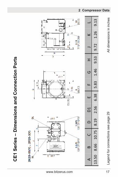
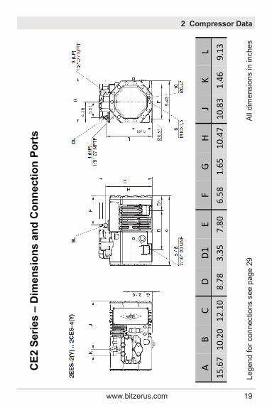
2.5 Dimensional Drawings and Connections
2 Compressor Data
www.bitzerus.com 17
C
E1
Se
rie
s –
Dim
en
sio
ns
an
d C
on
ne
cti
on
Po
rts
Fo
r L
eg
en
d G
o t
o P
ag
e 3
3
2 Compressor Data
Legend f
or
connectio
ns s
ee p
age 2
9
All
dim
ensio
ns in
inches
A
B
C
D
D1
E
F G
H
J
K
L
13
.50
8
.66
1
0.7
5
8.1
9
2.5
6
6.3
8
5.8
3
1.4
6
9.5
3
9.7
2
1.2
6
9.1
3
18 www.bitzerus.com
Se
rie
s
EC
OL
INE
Mo
de
l N
um
be
r
CE
22
EE
S-2
CE
22
EE
S-3
CE
22
DE
S-2
CE
22
DE
S-3
CE
22
CE
S-3
CE
22
CE
S-4
CE
2 S
eri
es
2 Compressor Data
www.bitzerus.com 19
C
E2
Se
rie
s –
Dim
en
sio
ns
an
d C
on
ne
cti
on
Po
rts
2 Compressor Data
Legend f
or
connectio
ns s
ee p
age 2
9
All
dim
ensio
ns in
inches
A
B
C
D
D1
E
F G
H
J
K
L
15
.67
1
0.2
0
12
.10
8
.78
3
.35
7
.80
6
.58
1
.65
1
0.4
7
10
.83
1
.46
9
.13
20 www.bitzerus.com
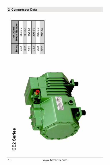
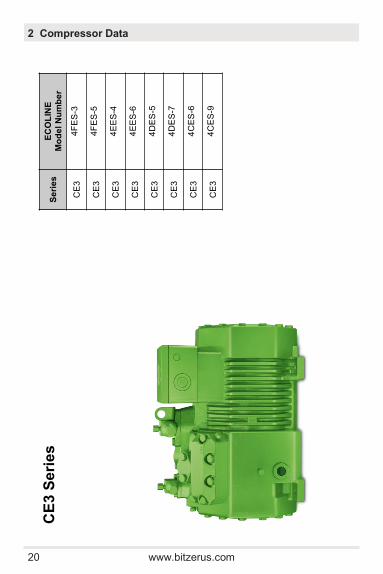
C
E3
Se
rie
sS
eri
es
E
CO
LIN
E
Mo
de
l N
um
be
r
CE
34
FE
S-3
CE
34
FE
S-5
CE
34
EE
S-4
CE
34
EE
S-6
CE
34
DE
S-5
CE
34
DE
S-7
CE
34
CE
S-6
CE
34
CE
S-9
2 Compressor Data

www.bitzerus.com 21
C
E3
Se
rie
s –
Co
nn
ec
tio
n P
ort
s
Legend f
or
connectio
ns s
ee p
age 2
9
All
dim
ensio
ns in
inches
2 Compressor Data
A
B
C
D
D1
E F
G
H
J K
L
17
.01
12
.17
13
.66
11
.54
2.
95
7.80
8.
70
1.6
5
12
.32
1
4.2
1
1.4
6
12
.05
4F
ES
4EES
17
.01
12
.17
13
.86
11
.54
2.
95
7.80
8.
70
2.2
1
12
.44
1
4.2
1
1.4
6
12
.05
4DES
-5
17.0
1
12.1
7
13.8
6
11.5
4
2.95
7.
80
8.70
2
.21
1
2.4
4
14
.21
1
.65
1
2.2
1
4DES
-7, 4
CES
18
.00
12
.17
13
.86
11
.54
3.
98
7.80
9.
69
2.2
1
12
.44
1
5.2
0
1.4
6
12
.21
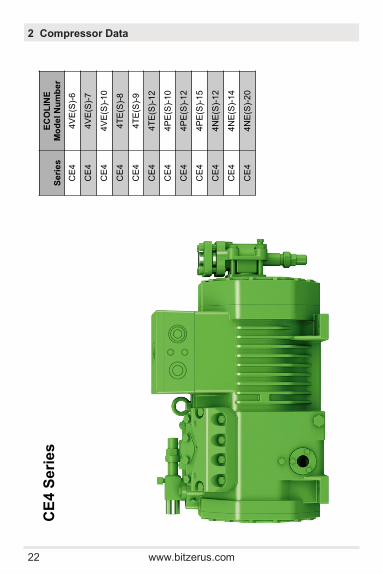
22 www.bitzerus.com
2 Compressor Data
CE
4 S
eri
es
Se
rie
s
EC
OL
INE
Mo
de
l N
um
be
r
CE
44
VE
(S)-
6
CE
44
VE
(S)-
7
CE
44
VE
(S)-
10
CE
44
TE
(S)-
8
CE
44
TE
(S)-
9
CE
44
TE
(S)-
12
CE
44
PE
(S)-
10
CE
44
PE
(S)-
12
CE
44
PE
(S)-
15
CE
44
NE
(S)-
12
CE
44
NE
(S)-
14
CE
44
NE
(S)-
20
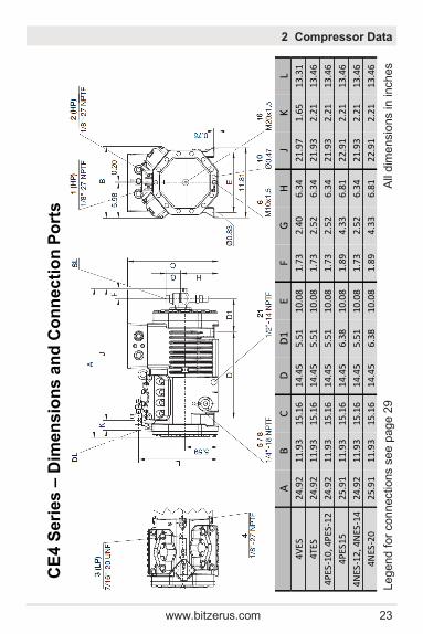
www.bitzerus.com 23
C
E4
Se
rie
s –
Dim
en
sio
ns
an
d C
on
ne
cti
on
Po
rts
2 Compressor Data
Legend f
or
connectio
ns s
ee p
age 2
9
All
dim
ensio
ns in
inches
A
B
C
D
D1
E
F G
H
J
K
L
24.9
2
11.9
3
15.1
6
14.4
5
5.51
10
.08
1.
73
2.4
0
6.3
4
21
.97
1
.65
1
3.3
1
4VES
4TES
24
.92
11
.93
15
.16
14
.45
5.
51
10.0
8
1.73
2
.52
6
.34
2
1.9
3
2.2
1
13
.46
4PES
-10
, 4P
ES-1
2
24.9
2
11.9
3
15.1
6
14.4
5
5.51
10
.08
1.
73
2.5
2
6.3
4
21
.93
2
.21
1
3.4
6
4PES
15
25.9
1
11.9
3
15.1
6
14.4
5
6.38
10
.08
1.
89
4.3
3
6.8
1
22
.91
2
.21
1
3.4
6
4NES
-12,
4N
ES-1
4
24.9
2
11.9
3
15.1
6
14.4
5
5.51
10
.08
1.
73
2.5
2
6.3
4
21
.93
2
.21
1
3.4
6
4NES
-20
25
.91
11
.93
15
.16
14
.45
6.
38
10.0
8
1.89
4
.33
6
.81
2
2.9
1
2.2
1
13
.46
24 www.bitzerus.com
2 Compressor Data
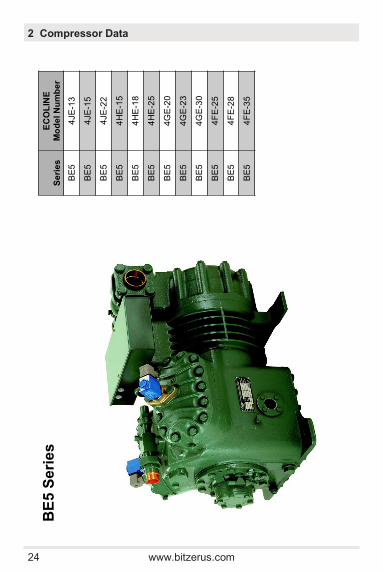
BE
5 S
eri
es
Se
rie
s
EC
OL
INE
Mo
de
l N
um
be
r
BE
54
JE
-13
BE
54
JE
-15
BE
54
JE
-22
BE
54
HE
-15
BE
54
HE
-18
BE
54
HE
-25
BE
54
GE
-20
BE
54
GE
-23
BE
54
GE
-30
BE
54
FE
-25
BE
54
FE
-28
BE
54
FE
-35
Seri
es
Mo
de
l
Nu
mb
er
Glo
ba
l M
od
el
Nu
mb
er
Eco
lin
e M
od
el
Nu
mb
er
B5
4B
27
07
PL
4J-1
3.3
4JE
-13Y
B5
4B
27
07
PH
4J-2
2.3
4JE
-22Y
B5
4B
31
39
PL
4H
-15.2
4H
E-1
5Y
B5
4B
31
39
PH
4H
-25.2
4H
-25Y
B5
4B
36
04
PL
4G
-20.2
4G
E-2
0Y
B5
4B
36
04
PH
4G
-30.2
4G
E-3
0Y
B5
Se
rie
s

www.bitzerus.com 25
B
E5
Se
rie
s –
Dim
en
sio
ns
an
d C
on
ne
cti
on
Po
rts
2 Compressor Data
Legend f
or
connectio
ns s
ee p
age 2
9
All
dim
ensio
ns in
inches
A
B
C
D
D1
E
F G
H
J
K
L
27.0
9
17.9
5
18.5
0
15.0
0
5.94
12
.01
2.
60
4.3
3
14
.21
1
9.7
2
2.2
1
14
.25
4J
E
4HE
-15
, 4H
E-1
8
27.0
9
17.9
5
18.5
0
15.0
0
5.94
12
.01
2.
60
4.3
3
14
.21
1
9.7
2
2.2
1
14
.25
4HE-
25
29.0
2
17.9
5
18.5
0
15.0
0
7.87
12
.01
3.
43
5.0
0
14
.84
2
1.6
1
2.2
1
14
.25
4GE
-20,
4GE
-23
27
.80
17
.95
18
.50
15
.00
6.
65
12.0
1
2.99
5
.00
1
4.8
4
20
.43
2
.21
1
4.2
5
4GE
-30
29
.02
17
.95
18
.50
15
.00
7.
87
12.0
1
3.43
5
.00
1
4.8
4
21
.61
2
.21
1
4.2
5
4FE
29
.02
17
.95
18
.50
15
.00
7.
87
12.0
1
3.43
5
.00
1
4.8
4
21
.61
2
.21
1
4.2
5
26 www.bitzerus.com
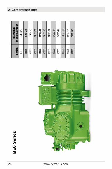
BE
6 S
eri
es
Seri
es
EC
OL
INE
Mo
de
l N
um
be
r
BE
66JE
-22
BE
66JE
-25
BE
66JE
-33
BE
66H
E-2
5
BE
66H
E-2
8
BE
66H
E-3
5
BE
66G
E-3
0
BE
66G
E-3
4
BE
66G
E-4
0
BE
66F
E-4
0
BE
66F
E-4
4
BE
66F
E-5
0
2 Compressor Data
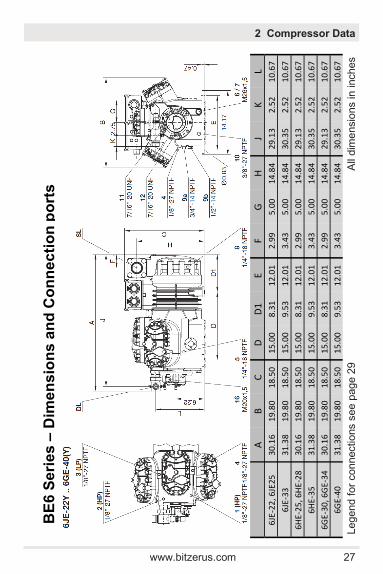
www.bitzerus.com 27
B
E6
Se
rie
s –
Dim
en
sio
ns
an
d C
on
ne
cti
on
po
rts
2 Compressor Data
Legend f
or
connectio
ns s
ee p
age 2
9
All
dim
ensio
ns in
inches
A
B
C
D
D1
E
F G
H
J
K
L
30.1
6
19.8
0
18.5
0
15.0
0
8.31
12
.01
2.
99
5.0
0
14
.84
2
9.1
3
2.5
2
10
.67
6J
E-2
2, 6
JE25
6JE
-33
31
.38
19
.80
18
.50
15
.00
9.
53
12.0
1
3.43
5
.00
1
4.8
4
30
.35
2
.52
1
0.6
7
6HE
-25
, 6H
E-2
8
30.1
6
19.8
0
18.5
0
15.0
0
8.31
12
.01
2.
99
5.0
0
14
.84
2
9.1
3
2.5
2
10
.67
6HE-
35
31.3
8
19.8
0
18.5
0
15.0
0
9.53
12
.01
3.
43
5.0
0
14
.84
3
0.3
5
2.5
2
10
.67
6GE
-30,
6G
E-3
4
30.1
6
19.8
0
18.5
0
15.0
0
8.31
12
.01
2.
99
5.0
0
14
.84
2
9.1
3
2.5
2
10
.67
6GE
-40
31
.38
19
.80
18
.50
15
.00
9.
53
12.0
1
3.43
5
.00
1
4.8
4
30
.35
2
.52
1
0.6
7

28 www.bitzerus.com
B
E6
Se
rie
s –
Dim
en
sio
ns
an
d C
on
ne
cti
on
po
rts
2 Compressor Data
Legend f
or
connectio
ns s
ee p
age 2
9
All
dim
ensio
ns in
inches
A
B
C
D
D
1 E
F G
H
J
K
L 6F
E
31.3
8
19.8
0
18.5
0
15.0
0
9.53
12
.01
3.
43
5.0
0
14
.84
2
8.7
1
4.3
7
15
.00
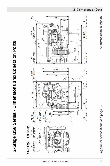
www.bitzerus.com 29
2 Compressor Data
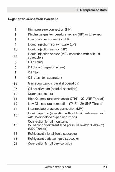
1 High pressure connection (HP)
2 Discharge gas temperature sensor (HP) or LI sensor
3 Low pressure connection (LP)
4 Liquid Injection: spray nozzle (LP)
4b Liquid Injection sensor (HP)
4c Liquid Injection sensor (MP / operation with a liquid subcooler)
5 Oil fill plug
6 Oil drain (magnetic screw)
7 Oil filter
8 Oil return (oil separator)
9a Gas equalization (parallel operation)
9b Oil equalization (parallel operation)
10 Crankcase heater
11 High Oil pressure connection (7/16” - 20 UNF Thread)
12 Low Oil pressure connection (7/16” - 20 UNF Thread)
14 Intermediate pressure connection (MP)
15 Liquid injection (operation without liquid subcooler and with thermostatic expansion valve)
16
Connection for oil monitoring (oil sensor or differential oil pressure switch “Delta-P”) (M20 Thread)
17 Refrigerant inlet at liquid subcooler
18 Refrigerant outlet at liquid subcooler
21 Connection for oil service valve
Legend for Connection Positions
30 www.bitzerus.com
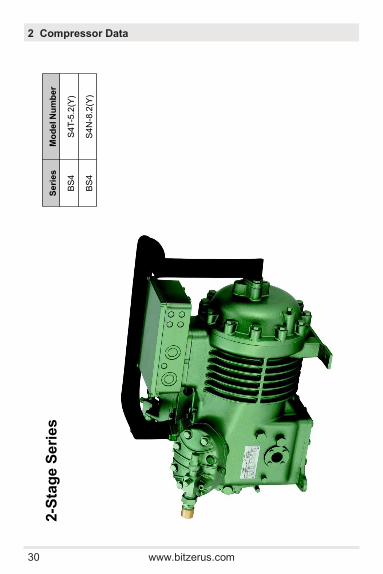
2-S
tag
e S
eri
es
Seri
es
Mo
de
l N
um
be
r
BS
4S
4T-5
.2(Y
)
BS
4S
4N
-8.2
(Y)
2 Compressor Data

www.bitzerus.com 31
2
-Sta
ge
SB
4 S
eri
es
-D
ime
ns
ion
s a
nd
Co
ne
cti
on
Po
rts
2 Compressor Data
Legend f
or
connectio
ns s
ee p
age 2
9
All
dim
ensio
ns in
inches
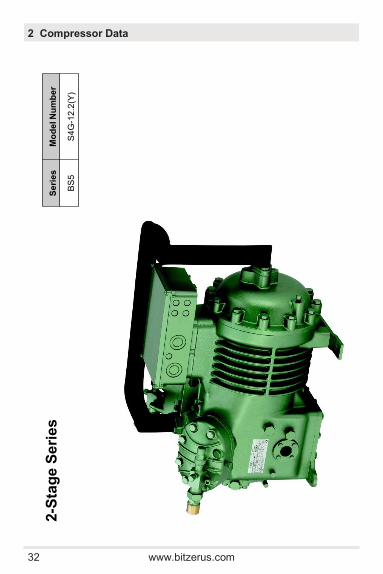
32 www.bitzerus.com
2-S
tag
e S
eri
es
Seri
es
Mo
de
l N
um
be
r
BS
5S
4G
-12
.2(Y
)
2 Compressor Data
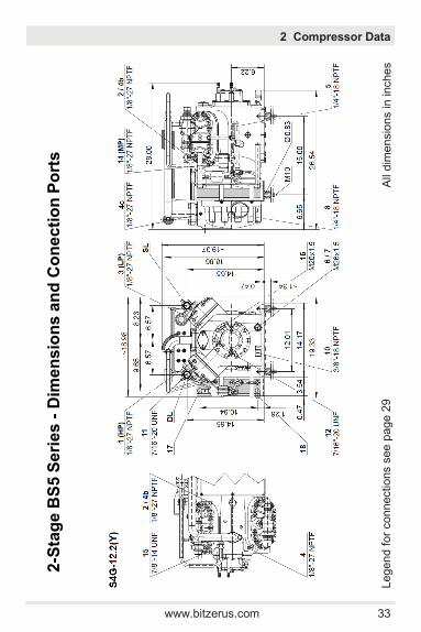
www.bitzerus.com 33
2
-Sta
ge
BS
5S
eri
es -
Dim
en
sio
ns a
nd
Co
necti
on
Po
rts
2 Compressor Data
Legend f
or
connectio
ns s
ee p
age 2
9
All
dim
ensio
ns in
inches
34 www.bitzerus.com
Fo
r L
eg
en
d G
o T
o P
ag
es 3
2-3
5
2-S
tag
e B
S6
Se
rie
sS
eri
es
Mo
de
l N
um
be
r
BS
6S
6J-1
6.2
(Y)
BS
6S
6H
-20.2
(Y)
BS
6S
6G
-25.2
(Y)
BS
6S
6F
-30.2
(Y)
2 Compressor Data
www.bitzerus.com 35
2-S
tag
e B
S6
Se
rie
s -
Dim
en
sio
ns
an
d C
on
ecti
on
Po
rts
2 Compressor Data
Legend f
or
connectio
ns s
ee p
age 3
9
All
dim
ensio
ns in
inches
36 www.bitzerus.com
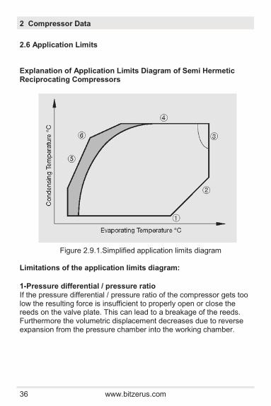
Explanation of Application Limits Diagram of Semi Hermetic Reciprocating Compressors
Figure 2.9.1.Simplified application limits diagram Limitations of the application limits diagram:
1-Pressure differential / pressure ratio If the pressure differential / pressure ratio of the compressor gets too low the resulting force is insufficient to properly open or close the reeds on the valve plate. This can lead to a breakage of the reeds. Furthermore the volumetric displacement decreases due to reverse expansion from the pressure chamber into the working chamber.
2.6 Application Limits
2 Compressor Data
www.bitzerus.com 37
2 Compressor Data
2-Maximum evaporating temperature If the compressor operates at an evaporating temperature close to the maximum allowed evaporating temperature the compressor deliv-ers a high refrigerant mass flow. Hence high forces develop on bear-ings and drive gear. 3-Motor Load The motor load of a semi hermetic reciprocating compressor de-pends on the operating point. The higher the evaporating tempera-ture and the higher the condensing temperature, the higher the corre-sponding motor load. 4-Maximum condensing temperature The maximum condensing temperature is limited by the saturated vapor pressure as well as the maximum allowable operating pressure on the high pressure side of the compressor. According to EN378-2 the maximum allowable operating pressure of the systems with pres-sure relief devices must not exceed 0.9 x maximum allowable operat-ing pressure. 5-Minimum evaporating temperature With decreasing evaporating temperature the saturated vapor pres-sure of the refrigerant decreases as well. For safe operation the cir-cuit should not be operated at pressures too much below ambient air in order to avoid penetration of ambient air into the suction side of the system through a leakage. At low evaporating temperatures the refrigerant mass flow of the compressor as well as the suction gas density are decreasing. This can possibly lead to an insufficient motor cooling as the delivered refrigerant mass flow is too low. 6-Thermal limit At low evaporating temperatures in combination with high condensing temperatures the thermal load limit of the compressor restricts the operation. There are various possibilities to extend the application limits such as water cooled cylinder heads, additional fans, restricting the allowable suction gas superheat or, in individual cases, a direct liquid injection into the suction side of the compressor. The recom-mended methods for additional cooling are displayed in the applica-tion limits diagram as icons.
38 www.bitzerus.com
2 Compressor Data
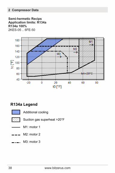
Semi-hermetic Recips Application limits: R134a R134a 100% 2KES-05 .. 6FE-50
R134a Legend Additional cooling Suction gas superheat >20°F M1: motor 1 M2: motor 2 M3: motor 3

www.bitzerus.com 39
2 Compressor Data
R404A / R507A Legend Additional cooling or suction gas superheat ≤35°F Additional cooling or max suction gas temp<40°F M1: motor 1 M2: motor 2
Semi-hermetic Recips Application limits: R404A and R507A R404A / R507A 100% 2KES-05 .. 6FE-50
40 www.bitzerus.com
2 Compressor Data
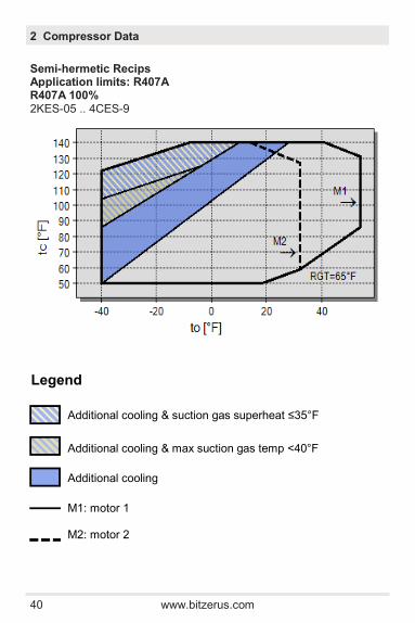
Semi-hermetic Recips Application limits: R407A R407A 100% 2KES-05 .. 4CES-9
Legend
Additional cooling & suction gas superheat ≤35°F
Additional cooling & max suction gas temp <40°F
Additional cooling
M1: motor 1 M2: motor 2
www.bitzerus.com 41
2 Compressor Data
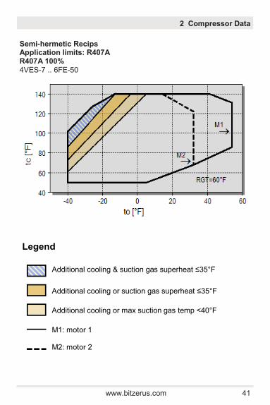
Semi-hermetic Recips Application limits: R407A R407A 100% 4VES-7 .. 6FE-50
Legend
Additional cooling & suction gas superheat ≤35°F
Additional cooling or suction gas superheat ≤35°F
Additional cooling or max suction gas temp <40°F
M1: motor 1 M2: motor 2
42 www.bitzerus.com
2 Compressor Data
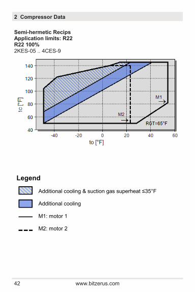
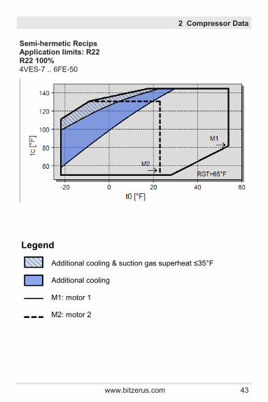
Semi-hermetic Recips Application limits: R22 R22 100% 2KES-05 .. 4CES-9
Legend Additional cooling & suction gas superheat ≤35°F Additional cooling M1: motor 1 M2: motor 2
www.bitzerus.com 43
2 Compressor Data
Semi-hermetic Recips Application limits: R22 R22 100% 4VES-7 .. 6FE-50
Legend Additional cooling & suction gas superheat ≤35°F Additional cooling M1: motor 1 M2: motor 2
44 www.bitzerus.com
2 Compressor Data
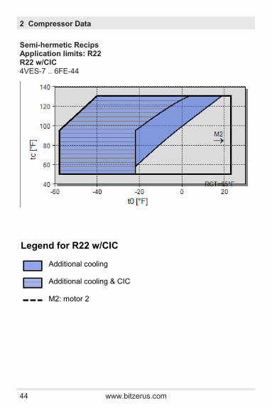
Semi-hermetic Recips Application limits: R22 R22 w/CIC 4VES-7 .. 6FE-44
Legend for R22 w/CIC Additional cooling Additional cooling & CIC M2: motor 2
www.bitzerus.com 45
2 Compressor Data
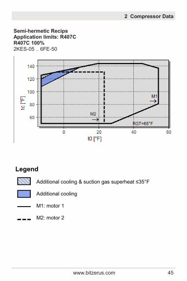
Semi-hermetic Recips Application limits: R407C R407C 100% 2KES-05 .. 6FE-50
Legend Additional cooling & suction gas superheat ≤35°F Additional cooling M1: motor 1 M2: motor 2

46 www.bitzerus.com
2 Compressor Data
2-Stage Semi-hermectic Recips: Application limits: R404A / 507A S4T .. S6F
R22 S4T .. S6F

www.bitzerus.com 47
2 Compressor Data
2.7 Operating Parameters
Parameter min max nominal
Discharge Temp SCT + 40°F (50°F w/R22) 250°F --
Oil Temp 95°F (55°F > SST) 175°F --
Superheat 15°F -- 20 - 30°F
Oil Pressure Diff 10psi -- 20 - 50psi
Temperatures and Pressures
Electrical
Parameter Trip Reset Ambient
Motor PTCs (M1 to M2) ≈4500Ω (≈280°F) ≈ 2700Ω 150 - 650Ω
Parameter Terminal Pins min max
Motor Windings (3PU, 4PU, 5PU) (6 pin terminal)
1-7 2-8 3-9
.3Ω 2.0Ω
Pin to ground OPEN
Motor Windings (2NU)* (9 pin terminal) *jumper bars removed
1-4 2-5 3-6
7-8 8-9 7-9
.3Ω 2.0Ω
OPEN Pin to ground
Variable Frequency Drives
Parameter* min max
CE1, CE2, CE3 30Hz 70Hz*
CE4, BE5 25Hz* 70Hz*
BE6 30Hz 70Hz*
*Consult BITZER AE department for operation between 25-30Hz and 60-70HZ
48 www.bitzerus.com
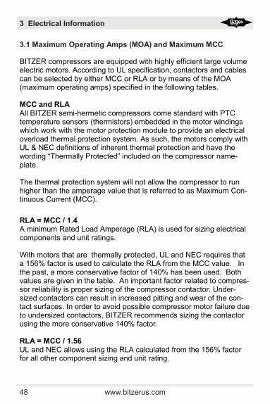
BITZER compressors are equipped with highly efficient large volume electric motors. According to UL specification, contactors and cables can be selected by either MCC or RLA or by means of the MOA (maximum operating amps) specified in the following tables. MCC and RLA All BITZER semi-hermetic compressors come standard with PTC temperature sensors (thermistors) embedded in the motor windings which work with the motor protection module to provide an electrical overload thermal protection system. As such, the motors comply with UL & NEC definitions of inherent thermal protection and have the wording “Thermally Protected” included on the compressor name-plate. The thermal protection system will not allow the compressor to run higher than the amperage value that is referred to as Maximum Con-tinuous Current (MCC).
RLA = MCC / 1.4 A minimum Rated Load Amperage (RLA) is used for sizing electrical components and unit ratings. With motors that are thermally protected, UL and NEC requires that a 156% factor is used to calculate the RLA from the MCC value. In the past, a more conservative factor of 140% has been used. Both values are given in the table. An important factor related to compres-sor reliability is proper sizing of the compressor contactor. Under-sized contactors can result in increased pitting and wear of the con-tact surfaces. In order to avoid possible compressor motor failure due to undersized contactors, BITZER recommends sizing the contactor using the more conservative 140% factor. RLA = MCC / 1.56 UL and NEC allows using the RLA calculated from the 156% factor for all other component sizing and unit rating.
3.1 Maximum Operating Amps (MOA) and Maximum MCC
3 Electrical Information
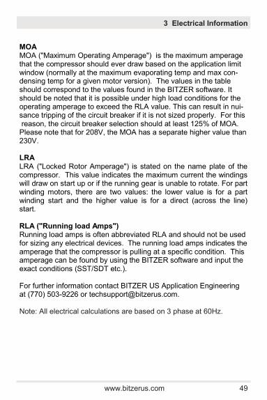
www.bitzerus.com 49
3 Electrical Information
MOA MOA ("Maximum Operating Amperage") is the maximum amperage that the compressor should ever draw based on the application limit window (normally at the maximum evaporating temp and max con-densing temp for a given motor version). The values in the table should correspond to the values found in the BITZER software. It should be noted that it is possible under high load conditions for the operating amperage to exceed the RLA value. This can result in nui-sance tripping of the circuit breaker if it is not sized properly. For this reason, the circuit breaker selection should at least 125% of MOA. Please note that for 208V, the MOA has a separate higher value than 230V. LRA LRA ("Locked Rotor Amperage") is stated on the name plate of the compressor. This value indicates the maximum current the windings will draw on start up or if the running gear is unable to rotate. For part winding motors, there are two values: the lower value is for a part winding start and the higher value is for a direct (across the line) start. RLA ("Running load Amps") Running load amps is often abbreviated RLA and should not be used for sizing any electrical devices. The running load amps indicates the amperage that the compressor is pulling at a specific condition. This amperage can be found by using the BITZER software and input the exact conditions (SST/SDT etc.). For further information contact BITZER US Application Engineering at (770) 503-9226 or [email protected]. Note: All electrical calculations are based on 3 phase at 60Hz.
50 www.bitzerus.com
3 Electrical Information
CE1 to CE3 Models
Mo
de
l N
um
-
ber
kW
C
FH
M
ax M
CC
L
RA
M
OA
230V
460V
575V
230V
460V
575V
230V
460V
575V
2K
ES
-05
0.3
7
173
7.6
3.6
2.7
32
16
12.8
5.6
2.8
2.2
2JE
S-0
7
0.5
6
222
9.4
4.5
3.3
40
20
16
7.4
3.7
3.0
2H
ES
-1
0.7
5
278
10.2
4.8
3.7
42
19
13
7.6
3.8
3.0
2H
ES
-2
1.5
278
15.5
6.3
5
54
24
17
9.5
4.5
3.6
2G
ES
-2
1.5
323
15.3
6.7
5.2
54
24
17
10.0
5.0
4.0
2F
ES
-2
1.5
407
14
6.4
5
54
24
17
10.6
5.3
4.2
2F
ES
-3
2.2
407
17.6
8
6.8
60
27.5
19
12.2
6.1
4.9
2E
ES
-2
1.5
486
16.8
7.6
5.6
70
28.5
20.5
12.0
6.0
4.8
2E
ES
-3
2.2
486
21.9
10.2
8.2
97
39.5
28.5
15.0
7.5
6.0
2D
ES
-2
1.5
571
18.3
9
6.6
80.5
33
23.5
15.0
7.5
6.0
2D
ES
-3
2.2
571
23.8
11.3
8
97
39.5
28.5
17.2
8.6
6.9
2C
ES
-3
2.2
691
20.9
9.8
7.9
97
39.5
28.5
18.2
9.1
7.3
2C
ES
-4
3.0
691
28.4
12.7
10.2
115
.5
47.5
34
20.0
10.0
8.0
4F
ES
-3
2.2
772
28.1
12.6
9.6
115
.5
47.5
34
20.0
9.5
7.6
4F
ES
-5
3.7
772
37.8
20.5
13.6
163
66.5
48
21.6
10.8
8.6
4E
ES
-4
3.0
968
31.4
14.4
11.6
142
58
41.5
24.4
12.2
9.8
4E
ES
-6
4.5
968
43.8
20.9
14.7
163
66.5
48
27.2
13.6
10.9
4D
ES
-5
3.7
114
2
32.2
16.8
14
163
66.5
48
29
14.5
11.6
4D
ES
-7
5.2
114
2
48.3
23.8
17.2
215
88
63.5
33
16.5
13.2
4C
ES
-6
4.5
138
5
39
22.1
17.5
215
88
63.5
35.4
17.7
14.2
4C
ES
-9
6.7
138
5
53.3
26.6
21.3
215
88
63.5
40.4
20.2
16.2
www.bitzerus.com 51
3 Electrical Information
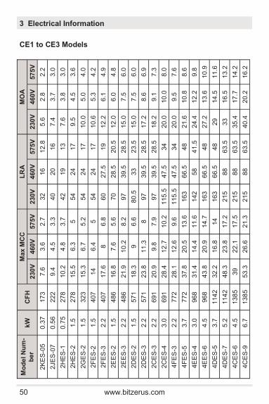
CE4 & BE5 Models
Mo
de
l N
um
ber
kW
C
FH
M
ax M
CC
L
RA
M
OA
230V
460V
575V
230V
460V
575V
230V
460V
575V
4V
E(S
)-6
4.5
147
9
38
19
15
150
75
60
18.8
9.4
7.5
4V
E(S
)-7
5.2
147
9
38
19
15
150
75
60
33.2
16.6
13.3
4V
E(S
)-10
7.5
147
9
60
30
24
222
111
89
39.8
19.9
15.9
4T
E(S
)-8
6.0
176
0
44
22
19
180
90
72
22.8
11.4
17.6
4T
E(S
)-9
6.7
176
0
44
22
19
180
90
72
39.8
19.9
15.9
4T
E(S
)-12
9.0
176
0
66
33
26.4
252
126
101
50.2
25.1
20.1
4P
E(S
)-10
7.5
206
7
54
27
22.4
222
111
89
25.8
12.9
10.3
4P
E(S
)-12
9.0
206
7
54
27
22.4
222
111
89
45.4
22.7
18.2
4P
E(S
)-15
11.2
206
7
76
38
30.5
294
147
117
56.4
28.2
22.6
4N
E(S
)-12
9.0
239
5
62
31
24.8
252
126
101
29.8
14.9
11.9
4N
E(S
)-14
10.4
239
5
62
31
24.8
252
126
101
53.2
26.6
21.3
4N
E(S
)-20
14.9
239
5
90
45
36.8
352
176
140
66.4
33.2
26.6
4JE
-13
9.7
270
7
68
34
27
294
147
117
37.6
18.8
15.0
4JE
-15
11.2
270
7
78
39
31.2
352
176
140
61.6
30.8
24.6
4JE
-22
16.4
270
7
96
48
38
352
176
140
74.4
37.2
29.8
4H
E-1
5
11.2
314
1
72
36
28.8
294
147
117
42.8
21.4
17.1
4H
E-1
8
13.4
314
1
84
42
33.8
352
176
140
73.4
36.7
29.4
4H
E-2
5
18.7
314
1
118
59
47
436
218
174
88.0
44.0
35.2
4G
E-2
0
14.9
360
6
90
45
36
352
176
140
49.2
24.6
19.7
4G
E-2
3
17.2
360
6
90
45
36
352
176
140
87.8
43.9
35.1
4G
E-3
0
22.4
360
6
140
70
56
490
245
196
102
.4
51.2
41.0
4F
E-2
5
18.7
433
9
120
60
48
436
218
174
56.4
28.2
22.6
4F
E-2
8
20.9
433
9
120
60
48
490
245
196
105
.6
52.8
42.2
4F
E-3
5
26.1
433
9
148
72
59
490
245
196
124
.2
62.1
49.7

52 www.bitzerus.com
3 Electrical Information
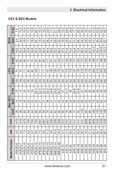
BE6, 8C & 2-Stage Models
Mo
de
l
Nu
mb
er
kW
C
FH
M
ax M
CC
L
RA
M
OA
230V
460V
575V
230V
460V
575V
230V
460V
575V
6JE
-22
16.4
406
2
102
51
41
436
218
174
53.2
26.6
21.3
6JE
-25
18.7
406
2
111
55
44
490
245
196
92.8
46.4
37.1
6JE
-33
24.6
406
2
156
78
62
550
275
220
106
.4
53.2
42.6
6H
E-2
5
18.7
471
0
108
54
43
436
218
174
62.6
31.3
25.0
6H
E-2
8
20.9
471
0
121
61
48
490
245
196
106
.4
53.2
42.6
6H
E-3
5
26.1
471
0
164
82
65
550
275
220
128
.8
64.4
51.5
6G
E-3
0
22.4
540
4
132
66
52
490
245
196
76.0
38.0
30.4
6G
E-3
4
25.4
540
4
132
66
52
490
245
196
131
.0
65.5
52.4
6G
E-4
0
29.8
540
4
220
110
88
700
350
280
147
.8
73.9
59.1
6F
E-4
0
29.8
646
1
152
76
61
700
350
280
97
48.5
38.8
6F
E-4
4
32.8
646
1
152
76
61
700
350
280
166
.4
83.2
66.6
6F
E-5
0
37.3
646
1
224
112
89
950
425
340
192
.4
96.2
77.0
8G
E-6
0
44.6
786
5
281
141
113
123
0
513
410
226
113
91
8F
E-7
0
52.2
941
9
329
164
132
128
8
590
472
278
139
112
S4T
-5.2
3.7
839
/53
7
28
28
11.2
150
75
60
28
14
11.2
S4N
-8.2
6
119
3/7
63
39.2
39.2
15.7
180
90
72
34
17
11.2
S4G
-12.2
9
180
3/1
15
1
56
56
22.4
252
126
101
48
24
19.2
S6J-1
6.2
12
270
7/1
35
5
84
84
33.6
294
147
117
62
31
24.8
S6H
-20.2
15
313
7/1
57
3
95.2
95.2
38
352
176
140
74
37
29.6
SG
6-2
5.2
18.5
360
2/1
80
3
116
116
46.4
436
218
174
86
43
34.4
S6F
-30
.2
22
430
9/2
15
2
134
.4
134
.4
53.5
490
245
196
81.6
51
40.8
www.bitzerus.com 53
3 Electrical Information
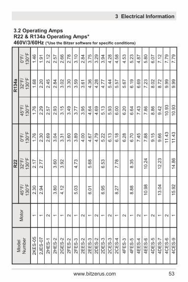
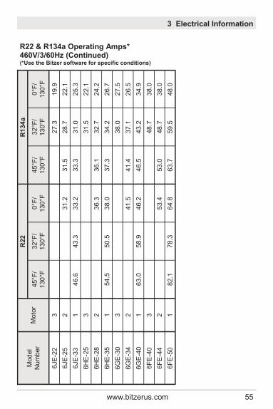
3.2 Operating Amps R22 & R134a Operating Amps* 460V/3/60Hz (*Use the Bitzer software for specific conditions)
Mod
el
Num
ber
Moto
r
R22
R
134
a
45°F
/ 130
°F
32°F
/ 130
°F
0°F
/ 130
°F
45°F
/ 130
°F
32°F
/ 130
°F
0°F
/ 130
°F
2K
ES
-05
1
2.3
0
2.1
7
1.7
6
1.7
6
1.6
8
1.4
6
2JE
S-0
7
1
2.9
4
2.7
7
2.3
0
2.2
9
2.2
0
1.9
1
2H
ES
-1
2
2.6
9
2.5
7
2.4
5
2.1
2
2H
ES
-2
1
3.8
0
3.6
0
3.0
4
2.9
3
2.8
4
2.5
7
2G
ES
-2
1
4.1
2
3.9
2
3.3
1
3.1
5
3.0
2
2.6
6
2F
ES
-2
2
3.6
0
3.4
9
3.3
0
2.7
8
2F
ES
-3
1
5.0
3
4.7
3
3.8
9
3.7
7
3.5
9
3.1
0
2E
ES
-2
2
4.0
0
3.9
5
3.6
1
2.8
4
2E
ES
-3
1
6.0
1
5.6
8
4.6
7
4.6
4
4.3
6
3.7
5
2D
ES
-2
2
4.7
9
4.6
9
4.2
8
3.2
9
2D
ES
-3
1
6.9
5
6.5
3
5.2
2
5.1
3
4.7
7
3.9
4
2C
ES
-3
2
6.1
3
5.9
3
5.4
4
4.2
8
2C
ES
-4
1
8.2
7
7.7
8
6.1
8
6.0
0
5.5
7
4.5
8
4F
ES
-3
2
6.2
8
6.2
0
5.6
7
4.5
3
4F
ES
-5
1
8.8
8
8.3
5
6.7
0
6.6
4
6.1
9
5.2
3
4E
ES
-4
2
7.4
5
7.4
3
6.6
9
4.8
7
4E
ES
-6
1
10.9
8
10.2
4
7.8
8
7.8
6
7.2
3
5.8
0
4D
ES
-5
2
9.1
5
8.8
6
8.0
2
6.0
7
4D
ES
-7
1
13.0
4
12.2
3
9.6
6
9.4
2
8.7
2
7.1
2
4C
ES
-6
2
11.4
3
10.9
3
9.9
9
7.7
9
4C
ES
-9
1
15.9
2
14.8
6
11.4
3
10.9
3
9.9
9
7.7
9

54 www.bitzerus.com
Mod
el
Num
ber
Moto
r
R22
R
134
a
45°F
/ 130
°F
32°F
/ 130
°F
0°F
/ 130
°F
45°F
/ 130
°F
32°F
/ 130
°F
0°F
/ 130
°F
4V
E(S
)-6
3
9.6
0
6.8
1
4V
E(S
)-7
2
10.6
6
10.7
3
9.6
0
6.8
1
4V
E(S
)-10
1
16.3
8
15.1
9
11.4
5
11.5
5
10.6
0
8.2
4
4T
E(S
)-8
3
11.6
4
8.1
7
4T
E(S
)-9
2
13.5
0
13.0
0
11.6
4
8.1
7
4T
E(S
)-12
1
19.6
4
18.1
5
13.5
3
13.5
8
12.3
7
9.4
5
4P
E(S
)-10
3
13.2
0
9.3
6
4P
E(S
)-12
2
14.5
8
14.7
3
13.2
0
9.3
6
4P
E(S
)-15
1
23.0
0
21.2
0
15.9
5
16.2
1
14.9
0
11.8
2
4N
E(S
)-12
3
15.3
4
10.7
9
4N
E(S
)-14
2
17.3
0
17.1
2
15.3
1
10.7
5
4N
E(S
)-20
1
26.3
0
24.3
0
18.3
0
18.6
0
17.0
9
13.5
4
4JE
-13
3
18.7
9
14.1
5
4JE
-15
2
20.1
0
20.2
0
18.6
3
14.6
7
4JE
-22
1
29.7
0
27.3
0
19.9
5
19.9
4
18.3
6
14.3
4
4H
E-1
5
3
21.4
0
15.5
3
4H
E-1
8
2
22.8
22.3
0
21.2
0
15.9
0
4H
E-2
5
1
35.5
0
32.9
0
24.9
0
24.5
0
22.7
0
18.0
7
4G
E-2
0
3
24.6
0
17.5
0
4G
E-2
3
2
27.4
0
26.5
0
23.7
0
16.7
3
4G
E-3
0
1
41.7
0
38.8
0
29.8
0
29.3
0
27.1
0
21.7
0
4F
E-2
5
3
30.6
0
21.8
0
4F
E-2
8
2
34.4
0
35.3
0
31.9
0
23.9
0
4F
E-3
5
1
49.6
0
45.8
0
34.1
0
34.5
0
31.2
0
23.3
0
R22 & R134a Operating Amps* 460V/3/60Hz (Continued) (*Use the Bitzer software for specific conditions)
3 Electrical Information
www.bitzerus.com 55
3 Electrical Information
R22 & R134a Operating Amps* 460V/3/60Hz (Continued) (*Use the Bitzer software for specific conditions)
Mod
el
Num
ber
Moto
r
R22
R
134
a
45°F
/ 130
°F
32°F
/ 130
°F
0°F
/ 130
°F
45°F
/ 130
°F
32°F
/ 130
°F
0°F
/ 130
°F
6JE
-22
3
27.3
19.9
6JE
-25
2
31.2
31.5
28.7
22.1
6JE
-33
1
46.6
43.3
33.2
33.3
31.0
25.3
6H
E-2
5
3
31.5
22.1
6H
E-2
8
2
36.3
36.1
32.7
24.2
6H
E-3
5
1
54.5
50.5
38.0
37.3
34.2
26.7
6G
E-3
0
3
38.0
27.5
6G
E-3
4
2
41.5
41.4
37.1
26.5
6G
E-4
0
1
63.0
58.9
46.2
46.5
43.2
34.9
6F
E-4
0
3
48.7
38.0
6F
E-4
4
2
53.4
53.0
48.7
38.0
6F
E-5
0
1
82.1
78.3
64.8
63.7
59.5
48.0
56 www.bitzerus.com
3 Electrical Information
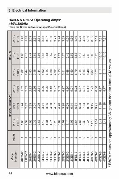
R404A & R507A Operating Amps* 460V/3/60Hz (*Use the Bitzer software for specific conditions)
Mod
el
Num
ber
Moto
r
R404
A / (
R5
07
A*)
R
407
A
20°F
/ 0°F
/ -2
5°F
/ 20°F
/ 0°F
/ -2
5°F
/
110
°F
110
°F
110
°F
110
°F
110
°F
110
°F
2K
ES
-05
1
1.8
8
1.7
4
1.5
2
1.8
2
1.6
3
1.4
0
2JE
S-0
7
1
2.5
4
2.3
2
2.0
2
2.4
4
2.1
8
1.8
8
2H
ES
-1
2
3.0
3
2.6
5
2.2
2
2.8
3
2.4
7
2.0
9
2H
ES
-2
1
3.3
3
3.0
4
2.6
6
3.1
6
2.8
6
2.5
4
2G
ES
-2
1
3.6
5
3.2
9
2.8
1
3.4
4
3.0
6
2.6
4
2F
ES
-2
2
4.1
9
3.7
1
3.0
6
4.0
2
3.4
5
2.8
2
2F
ES
-3
1
4.3
4
3.8
6
3.2
6
4.1
5
3.6
4
3.0
7
2E
ES
-2
2
4.7
1
4.0
0
3.1
3
4.3
0
3.5
7
2.8
0
2E
ES
-3
1
5.2
6
4.6
7
3.9
7
4.9
2
4.3
3
3.7
1
2D
ES
-2
2
5.6
4
4.7
8
3.6
9
5.1
3
4.2
4
3.2
4
2D
ES
-3
1
5.9
7
5.2
0
4.2
7
5.5
1
4.7
4
3.8
9
2C
ES
-3
2
7.1
1
6.0
8
4.8
0
6.4
8
5.4
3
4.2
5
2C
ES
-4
1
7.0
7
6.1
4
5.0
1
6.5
0
5.5
6
4.5
6
4F
ES
-3
2
7.6
4
6.6
1
5.2
8
6.7
9
5.6
6
4.4
9
4F
ES
-5
1
7.8
6
6.9
8
5.8
7
7.1
4
6.1
8
5.2
0
4E
ES
-4
2
9.3
0
7.8
3
5.8
1
8.1
4
6.5
0
4.5
9
4E
ES
-6
1
9.4
1
8.0
9
6.4
1
8.4
8
7.0
8
5.5
9
4D
ES
-5
2
11.1
6
9.4
5
7.2
1
9.8
7
8.0
6
6.0
5
4D
ES
-7
1
11.3
7
9.9
1
8.0
6
10.2
6
8.7
6
7.1
1
4C
ES
-6
2
13.4
2
11.3
6
8.7
7
12.1
4
10.1
0
7.8
1
4C
ES
-9
1
13.4
2
11.3
6
8.7
7
12.1
4
10.1
0
7.8
1
* R
507A
valu
es a
re a
ppro
xim
ate
ly 3
% g
reate
r th
an t
he lis
ted 4
04A
valu
es.
www.bitzerus.com 57
3 Electrical Information
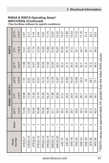
R404A & R507A Operating Amps* 460V/3/60Hz (Continued) (*Use the Bitzer software for specific conditions)
* R
507A
valu
es a
re a
ppro
xim
ate
ly 3
% g
reate
r th
an t
he lis
ted 4
04A
valu
es.
Mod
el
Num
ber
Moto
r
R404
A / (
R5
07
A*)
R
407
A
20°F
/ 0°F
/ -2
5°F
/ 20°F
/ 0°F
/ -2
5°F
/
110
°F
110
°F
110
°F
110
°F
110
°F
110
°F
4V
E(S
)-7
2
13.5
5
10.8
8
7.7
2
11.8
8
9.4
3
6.5
7
4V
E(S
)-10
1
13.8
7
11.6
6
9.0
4
12.4
8
10.4
3
8.1
1
4T
E(S
)-9
2
16.5
4
13.4
2
9.5
3
14.6
7
11.7
4
8.1
6
4T
E(S
)-12
1
16.4
8
13.7
4
10.5
1
14.8
5
12.3
4
9.4
4
4P
E(S
)-12
2
18.5
2
15.0
5
10.7
3
16.5
0
13.2
0
9.3
0
4P
E(S
)-15
1
19.3
6
16.2
7
12.7
8
17.5
9
14.8
0
11.7
5
4N
E(S
)-14
2
21.1
17.9
6
12.7
8
19.5
0
15.5
3
10.8
7
4N
E(S
)-20
1
22.4
18.8
4
14.8
7
20.0
16.8
7
13.4
2
4JE
-15
2
25.2
21.2
16.3
4
22.3
18.3
4
14.0
7
4JE
-22
1
24.5
20.5
15.8
2
21.9
18.1
2
13.9
5
4H
E-1
8
2
29.7
24.6
18.3
0
26.0
21.0
15.5
3
4H
E-2
5
1
29.8
25.3
19.9
8
26.4
22.1
17.3
3
4G
E-2
3
2
35.2
28.7
20.8
30.7
24.7
17.7
9
4G
E-3
0
1
35.3
30.1
24
31.4
26.7
21.4
4F
E-2
8
2
43.3
36.4
26.7
37.5
31.1
23.7
4F
E-3
5
1
42.4
35.7
27.1
36.5
30.2
23.0
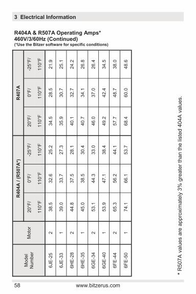
58 www.bitzerus.com
3 Electrical Information
Mod
el
Num
ber
Moto
r
R404
A / (
R5
07
A*)
R
407
A
20°F
/ 0°F
/ -2
5°F
/ 20°F
/ 0°F
/ -2
5°F
/
110
°F
110
°F
110
°F
110
°F
110
°F
110
°F
6JE
-25
2
38.5
32.6
25.2
34.5
28.5
21.9
6JE
-33
1
39.0
33.7
27.3
35.9
30.7
25.1
6H
E-2
8
2
44.8
37.5
28.1
40.1
32.7
24.2
6H
E-3
5
1
45.0
38.5
30.4
40.7
34.1
26.8
6G
E-3
4
2
53.1
44.3
33.0
46.0
37.0
26.4
6G
E-4
0
1
53.9
47.1
38.4
49.2
42.4
34.5
6F
E-4
4
2
65.3
56.2
44.1
57.7
48.7
38.0
6F
E-5
0
1
74.1
66.1
53.7
68.4
60.0
48.6
R404A & R507A Operating Amps* 460V/3/60Hz (Continued) (*Use the Bitzer software for specific conditions)
* R
507A
valu
es a
re a
ppro
xim
ate
ly 3
% g
reate
r th
an t
he lis
ted 4
04A
valu
es.
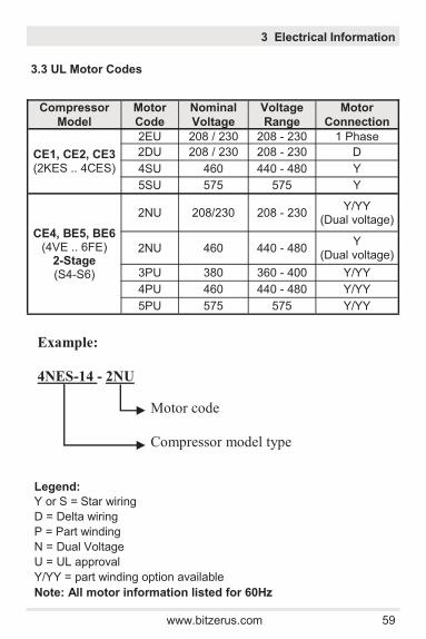
www.bitzerus.com 59
3 Electrical Information
3.3 UL Motor Codes
Compressor
Model
Motor
Code
Nominal
Voltage
Voltage
Range
Motor
Connection
CE1, CE2, CE3 (2KES .. 4CES)
2EU 208 / 230 208 - 230 1 Phase
2DU 208 / 230 208 - 230 D
4SU 460 440 - 480 Y
5SU 575 575 Y
CE4, BE5, BE6 (4VE .. 6FE)
2-Stage (S4-S6)
2NU 208/230 208 - 230 Y/YY
(Dual voltage)
2NU 460 440 - 480 Y
(Dual voltage)
3PU 380 360 - 400 Y/YY
4PU 460 440 - 480 Y/YY
5PU 575 575 Y/YY
Legend:
Y or S = Star wiring
D = Delta wiring
P = Part winding
N = Dual Voltage
U = UL approval
Y/YY = part winding option available
Note: All motor information listed for 60Hz
Example:
4NES-14 - 2NU
Motor code
Compressor model type

60 www.bitzerus.com
3.4 Wiring Diagrams / Power Connection Direct Start 2NU Motor 230V or 460V/3/60Hz
ATTENTION! Terminals B1- B2, M1- M2 and cables 1-2 must not come into contact with supply or control voltage.
3 Electrical Information
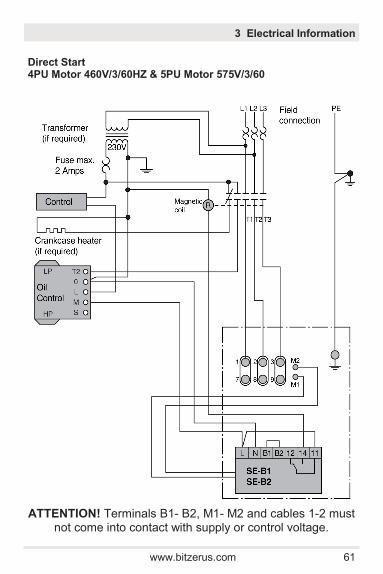
www.bitzerus.com 61
Direct Start 4PU Motor 460V/3/60HZ & 5PU Motor 575V/3/60
ATTENTION! Terminals B1- B2, M1- M2 and cables 1-2 must not come into contact with supply or control voltage.
3 Electrical Information
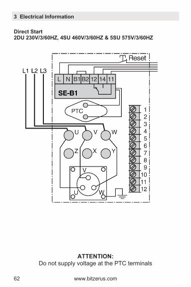
62 www.bitzerus.com
Direct Start 2DU 230V/3/60HZ, 4SU 460V/3/60HZ & 5SU 575V/3/60HZ
ATTENTION: Do not supply voltage at the PTC terminals
3 Electrical Information

www.bitzerus.com 63
4 Accessories/Options
Direct Start 2EU 1 Phase (UL)
Legend
A = Comp. control circuit
CA = Start capacitor
CB = Run Capacitor
JP = Field installation jumper (req'd)
RY = Start relay
T1/T2 = From compressor contactor
B1/B2 = Remove B1/B2 to enable "automatic reset" mode
ATTENTION: Do not supply voltage at the PTC terminals
Bleed Resistor = 15000Ω
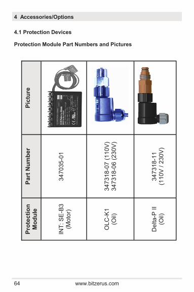
64 www.bitzerus.com
4 Accessories/Options
4.1 Protection Devices
Protection Module Part Numbers and Pictures
Pro
tec
tio
n
Mo
du
le
Pa
rt N
um
be
r P
ictu
re
IN
T:
SE
-B3
(Mo
tor)
3
47
035-0
1
O
LC
-K1
(O
il)
3
47
318-0
7 (
11
0V
) 3
47
318-0
6 (
23
0V
)
D
elta-P
II
(Oil)
3
47
318-1
1
(11
0V
/ 2
30
V)
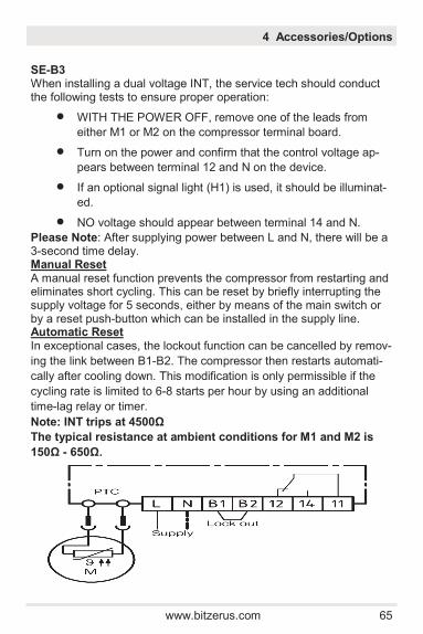
www.bitzerus.com 65
SE-B3 When installing a dual voltage INT, the service tech should conduct the following tests to ensure proper operation:
WITH THE POWER OFF, remove one of the leads from
either M1 or M2 on the compressor terminal board.
Turn on the power and confirm that the control voltage ap-
pears between terminal 12 and N on the device.
If an optional signal light (H1) is used, it should be illuminat-
ed.
NO voltage should appear between terminal 14 and N.
Please Note: After supplying power between L and N, there will be a 3-second time delay. Manual Reset A manual reset function prevents the compressor from restarting and eliminates short cycling. This can be reset by briefly interrupting the supply voltage for 5 seconds, either by means of the main switch or by a reset push-button which can be installed in the supply line. Automatic Reset In exceptional cases, the lockout function can be cancelled by remov-
ing the link between B1-B2. The compressor then restarts automati-
cally after cooling down. This modification is only permissible if the
cycling rate is limited to 6-8 starts per hour by using an additional
time-lag relay or timer.
Note: INT trips at 4500Ω
The typical resistance at ambient conditions for M1 and M2 is
150Ω - 650Ω.
4 Accessories/Options

66 www.bitzerus.com
4 Accessories/Options
Oil Monitoring Devices: Delta-P II: Monitors oil pressure differential of compressors with oil pumps OLC-K1: Optically monitors oil presence at the crankshaft of centrifugal disk (“S”) compressors
Technical Features:
The Delta-P II and OLC-K1 consists of two parts: a sensor unit
and an electronic unit.
Because the mechanical component screws separately into the
BITZER housing, the hermetically sealed electrical unit can be
replaced without refrigerant or oil loss.
Device Trip:
Delta-P II:
If the differential oil pressure drops below 9.5 ± 2 psid (for any
amount of time) a red light will illuminate on the front of the elec-
trical unit.
If the pressure remains below for 9.5 ± 2 psid for longer than the
allowable time (see chart on p.70) then the output relay opens
(stopping the compressor).
OLC-K1:
If there is no oil present for any amount of time in the oil pocket
(center of front bearing cap), a red light will illuminate on the
front of the electrical unit.
If no oil is sensed for longer than the allowable time (see chart
on p.70) then the output relay opens (stopping the compressor).
Delta-P II / OLC-K1:
In case the supply voltage is too low or if the electronic unit is
not properly mounted, the device will lock out after 5 seconds.
The LED at the front end of the electronic unit will flash.
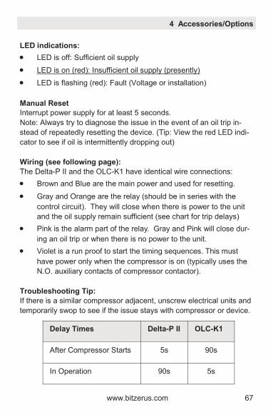
www.bitzerus.com 67
4 Accessories/Options
LED indications:
LED is off: Sufficient oil supply
LED is on (red): Insufficient oil supply (presently)
LED is flashing (red): Fault (Voltage or installation)
Manual Reset
Interrupt power supply for at least 5 seconds.
Note: Always try to diagnose the issue in the event of an oil trip in-
stead of repeatedly resetting the device. (Tip: View the red LED indi-
cator to see if oil is intermittently dropping out)
Wiring (see following page):
The Delta-P II and the OLC-K1 have identical wire connections:
Brown and Blue are the main power and used for resetting.
Gray and Orange are the relay (should be in series with the
control circuit). They will close when there is power to the unit
and the oil supply remain sufficient (see chart for trip delays)
Pink is the alarm part of the relay. Gray and Pink will close dur-
ing an oil trip or when there is no power to the unit.
Violet is a run proof to start the timing sequences. This must
have power only when the compressor is on (typically uses the
N.O. auxiliary contacts of compressor contactor).
Troubleshooting Tip:
If there is a similar compressor adjacent, unscrew electrical units and
temporarily swop to see if the issue stays with compressor or device.
Delay Times Delta-P II
OLC-K1
After Compressor Starts 5s 90s
In Operation
90s
5s
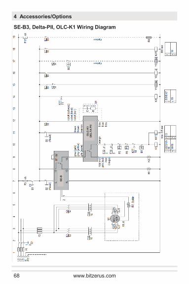
68 www.bitzerus.com
4 Accessories/Options
SE-B3, Delta-PII, OLC-K1 Wiring Diagram
OL
C-K
1
DE
LT
A P
II
SE
-B
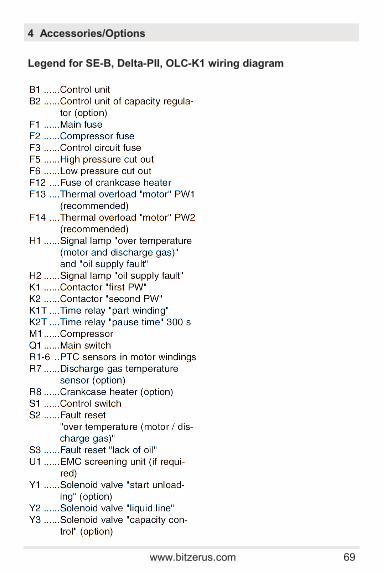
www.bitzerus.com 69
Legend for SE-B, Delta-PII, OLC-K1 wiring diagram
4 Accessories/Options
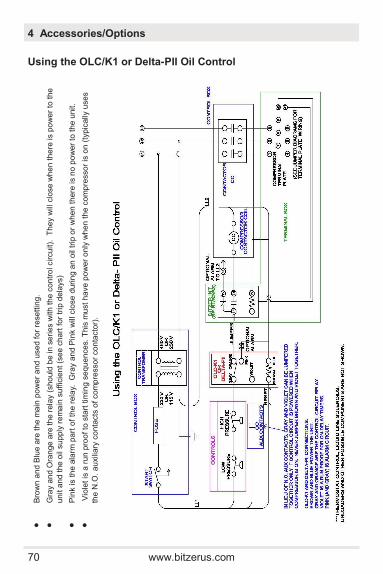
70 www.bitzerus.com
4 Accessories/Options
Using the OLC/K1 or Delta-PII Oil Control
Bro
wn
an
d B
lue
are
th
e m
ain
po
we
r a
nd
use
d f
or
rese
ttin
g.
Gra
y a
nd
Ora
nge
are
th
e r
ela
y (
sho
uld
be
in s
eri
es w
ith
th
e c
on
tro
l cir
cuit).
T
he
y w
ill c
lose w
he
n t
he
re is p
ow
er
to t
he
un
it a
nd
the
oil
su
pply
re
ma
in s
uffic
ien
t (s
ee
ch
art
for
trip
dela
ys)
Pin
k is t
he
ala
rm p
art
of
the
rela
y.
Gra
y a
nd P
ink w
ill c
lose
du
rin
g a
n o
il tr
ip o
r w
he
n t
here
is n
o p
ow
er
to t
he u
nit.
Vio
let is
a r
un
pro
of to
sta
rt tim
ing
se
qu
en
ce
s.
This
mu
st
ha
ve
po
we
r o
nly
wh
en
th
e c
om
pre
sso
r is
on
(ty
pic
ally
use
s
the
N.O
. a
uxili
ary
co
nta
cts
of
co
mp
resso
r co
nta
cto
r).

www.bitzerus.com 71
4 Accessories/Options
4.2 Other Oil Monitoring Devices and Adaptors Part Numbers
Co
mp
res
so
r M
od
el
Oth
er
Oil M
on
ito
rin
g D
evic
es
an
d a
da
pto
rs
Pre
ss
ure
d
iffe
ren
tia
l S
igh
t G
lass
Oil
Le
ve
l
Oil S
afe
ty T
yp
e
Pa
rt N
um
ber
Lu
bri
ca
tio
n
Typ
e
Min
i-m
um
N
om
ina
l
CE
1
(2K
ES
.. 2
FE
S)
Oil
Flo
at A
da
pte
r 990-8
000-0
2
Ce
ntr
ifu
ga
l D
isk
- -
1/4
to
3
/4
Fu
ll
Mech
an
ica
l O
il F
loat
794-0
201-0
5
CE
2
(2E
ES
.. 2
CE
S)
Oil
Flo
at A
da
pte
r 990-8
000-0
2
Ce
ntr
ifu
ga
l D
isk
- -
Mech
an
ica
l O
il F
loat
794-0
201-0
5
CE
3
(4F
ES
.. 4
CE
S)
Oil
Flo
at A
da
pte
r 990-8
000-0
2
Ce
ntr
ifu
ga
l D
isk
- -
Mech
an
ica
l O
il F
loat
794-0
201-0
5
CE
4
(4V
E .. 4
NE
)
MP
54
860-3
002-0
1
Pu
mp
9p
si
20-3
5
psi
P545
860-3
003-0
1
Pu
mp
Mech
an
ica
l O
il F
loat
794-0
201-0
5
Bo
th
BE
5 -
BE
6
(4J
E .. 6
FE
) 2-S
tag
e
(S4
.. S
6)
Pu
mp
9p
si
20-5
0
psi
MP
54
860-3
002-0
1
P545
860-3
003-0
1
Oil
Flo
at A
da
pte
r 990-8
000-0
1
Mech
an
ica
l O
il F
loat
794-0
201-0
5
4 B
olt -
3 B
olt
Oil
Flo
at A
dapte
r P
N# -
990-8
000
-01
Th
read -
3 B
olt
Oil
Flo
at A
dapte
r P
N# -
990-8
000
-02
Mechanic
al
Oil
Flo
at
PN
# -
794-0
201
-05
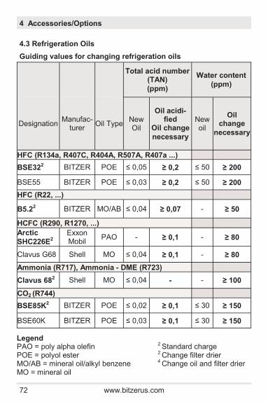
72 www.bitzerus.com
4 Accessories/Options
4.3 Refrigeration Oils
Guiding values for changing refrigeration oils
Legend PAO = poly alpha olefin 2 Standard charge POE = polyol ester 2 Change filter drier MO/AB = mineral oil/alkyl benzene 4 Change oil and filter drier MO = mineral oil
Total acid number (TAN)
(ppm)
Water content
(ppm)
Designation Manufac-
turer Oil Type
New Oil
Oil acidi-fied
Oil change
necessary
New oil
Oil change
necessary
HFC (R134a, R407C, R404A, R507A, R407a ...)
BSE322 BITZER POE ≤ 0,05 ≥ 0,2 ≤ 50 ≥ 200
BSE55 BITZER POE ≤ 0,03 ≥ 0,2 ≤ 50 ≥ 200
HFC (R22, ...)
B5.22 BITZER MO/AB ≤ 0,04 ≥ 0,07 - ≥ 50
HCFC (R290, R1270, ...)
Arctic
SHC226E2 Exxon Mobil
PAO - ≥ 0,1 - ≥ 80
Clavus G68 Shell MO ≤ 0,04 ≥ 0,1 - ≥ 80
Ammonia (R717), Ammonia - DME (R723)
Clavus 682 Shell MO ≤ 0,04 - - ≥ 100
CO2 (R744)
BSE85K2 BITZER POE ≤ 0,02 ≥ 0,1 ≤ 30 ≥ 150
BSE60K BITZER POE ≤ 0,03 ≥ 0,1 ≤ 30 ≥ 150
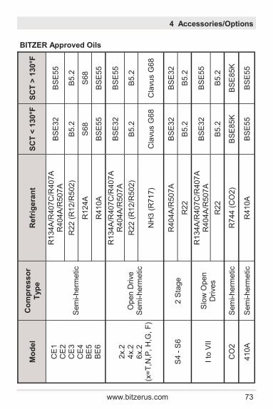
www.bitzerus.com 73
4 Accessories/Options
BITZER Approved Oils
Mo
de
l C
om
pre
sso
r
Typ
e
Refr
ige
ran
t S
CT
< 1
30
°F
SC
T >
130°F
CE
1
CE
2
CE
3
CE
4
BE
5
BE
6
Sem
i-herm
etic
R134A
/R407C
/R407A
R404A
/R507A
B
SE
32
B
SE
55
R22 (
R12/R
502)
B5.2
B
5.2
R124A
S
68
S68
R410A
B
SE
55
B
SE
55
2x.2
4x.2
6x.2
(x
=T
,N,P
, H
,G, F
)
Open D
rive
Sem
i-herm
etic
R134A
/R407C
/R407A
R404A
/R507A
B
SE
32
B
SE
55
R22 (
R12/R
502)
B5.2
B
5.2
NH
3 (
R717)
Cla
vus G
68
Cla
vus G
68
S4 -
S6
2 S
tage
R404A
/R507A
B
SE
32
B
SE
32
R22
B5.2
B
5.2
I to
VII
Slo
w O
pen
Drives
R134A
/R407C
/R407A
R404A
/R507A
B
SE
32
B
SE
55
R22
B5.2
B
5.2
CO
2
Sem
i-herm
etic
R744 (
CO
2)
BS
E85K
B
SE
85K
410A
S
em
i-herm
etic
R410A
B
SE
55
B
SE
55
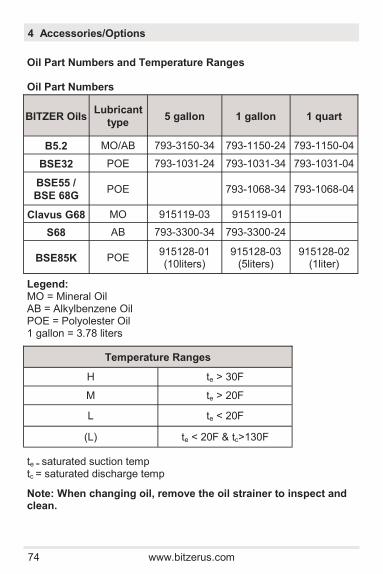
74 www.bitzerus.com
4 Accessories/Options
Oil Part Numbers and Temperature Ranges Oil Part Numbers
te = saturated suction temp tc = saturated discharge temp
Legend: MO = Mineral Oil AB = Alkylbenzene Oil POE = Polyolester Oil 1 gallon = 3.78 liters
BITZER Oils Lubricant
type 5 gallon 1 gallon 1 quart
B5.2 MO/AB 793-3150-34 793-1150-24 793-1150-04
BSE32 POE 793-1031-24 793-1031-34 793-1031-04
BSE55 /
BSE 68G POE 793-1068-34 793-1068-04
Clavus G68 MO 915119-03 915119-01
S68 AB 793-3300-34 793-3300-24
BSE85K POE 915128-01 (10liters)
915128-03 (5liters)
915128-02 (1liter)
Temperature Ranges
H te > 30F
M te > 20F
L te < 20F
(L) te < 20F & tc>130F
Note: When changing oil, remove the oil strainer to inspect and clean.
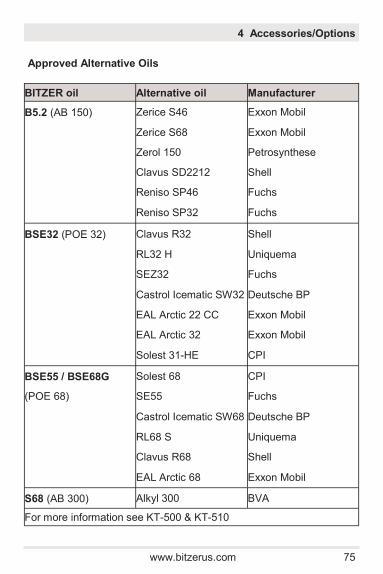
www.bitzerus.com 75
Approved Alternative Oils
4 Accessories/Options
BITZER oil Alternative oil Manufacturer
B5.2 (AB 150) Zerice S46 Exxon Mobil
Zerice S68 Exxon Mobil
Zerol 150 Petrosynthese
Clavus SD2212 Shell
Reniso SP46 Fuchs
Reniso SP32 Fuchs
BSE32 (POE 32) Clavus R32 Shell
RL32 H Uniquema
SEZ32 Fuchs
Castrol Icematic SW32 Deutsche BP
EAL Arctic 22 CC Exxon Mobil
EAL Arctic 32 Exxon Mobil
Solest 31-HE CPI
BSE55 / BSE68G Solest 68 CPI
(POE 68) SE55 Fuchs
Castrol Icematic SW68 Deutsche BP
RL68 S Uniquema
Clavus R68 Shell
EAL Arctic 68 Exxon Mobil
S68 (AB 300) Alkyl 300 BVA
For more information see KT-500 & KT-510
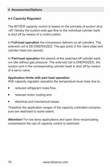
76 www.bitzerus.com
4.4 Capacity Regulator
The BITZER capacity control is based on the principle of suction shut
-off. Hereby the suction-side gas flow to the individual cylinder bank
is shut off by means of a control piston.
In Full-load operation the compressor delivers on all cylinders. The
solenoid coil is DE-ENERGIZED. The gas ports in the valve plate and
cylinder head are opened.
In Part-load operation the pistons of the switched-off cylinder bank
run idle without gas pressure. The solenoid coil is ENERGIZED, the
suction port in the corresponding cylinder head is shut off by means
of a servo valve.
Application limits with part load operation With capacity regulator operation the temperature level rises due to:
reduced refrigerant mass flow,
reduced motor cooling and
electrical and mechanical losses.
Therefore the application ranges of the capacity controlled compres-
sors are restricted to some extent.
Attention! For low temp applications and open drive reciprocating
compressors the use of capacity control is restricted.
4 Accessories/Options
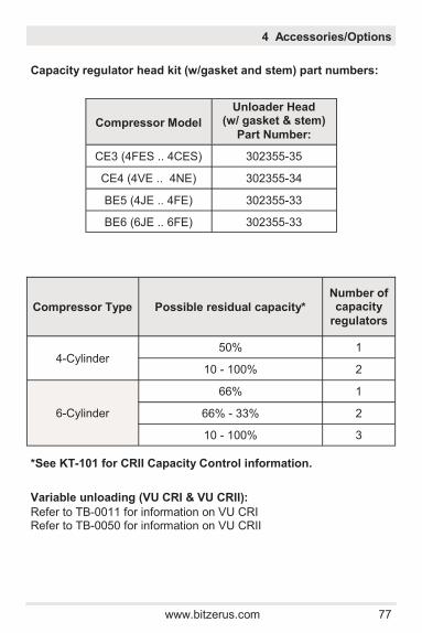
www.bitzerus.com 77
4 Accessories/Options
Capacity regulator head kit (w/gasket and stem) part numbers:
*See KT-101 for CRII Capacity Control information.
Variable unloading (VU CRI & VU CRII):
Refer to TB-0011 for information on VU CRI Refer to TB-0050 for information on VU CRII
Compressor Model
Unloader Head (w/ gasket & stem)
Part Number:
CE3 (4FES .. 4CES) 302355-35
CE4 (4VE .. 4NE) 302355-34
BE5 (4JE .. 4FE) 302355-33
BE6 (6JE .. 6FE) 302355-33
Compressor Type Possible residual capacity*
Number of capacity
regulators
4-Cylinder 50% 1
10 - 100% 2
6-Cylinder
66% 1
66% - 33% 2
10 - 100% 3
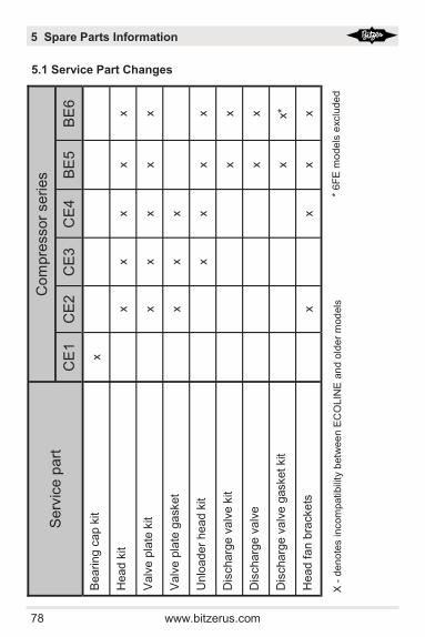
78 www.bitzerus.com
5 Spare Parts Information
5.1 Service Part Changes S
erv
ice p
art
C
om
pre
ssor
series
CE
1
CE
2
CE
3
CE
4
BE
5
BE
6
Bearin
g c
ap k
it
x
Head k
it
x
x
x
x
x
Valv
e p
late
kit
x
x
x
x
x
Valv
e p
late
gasket
x
x
x
Unlo
ader
head k
it
x
x
x
x
Dis
charg
e v
alv
e k
it
x
x
Dis
charg
e v
alv
e
x
x
Dis
charg
e v
alv
e g
asket kit
x
x*
Head f
an b
rackets
x
x
x
x
X -
den
ote
s incom
patibili
ty b
etw
ee
n E
CO
LIN
E a
nd o
lde
r m
od
els
*
6F
E m
odels
exclu
de
d
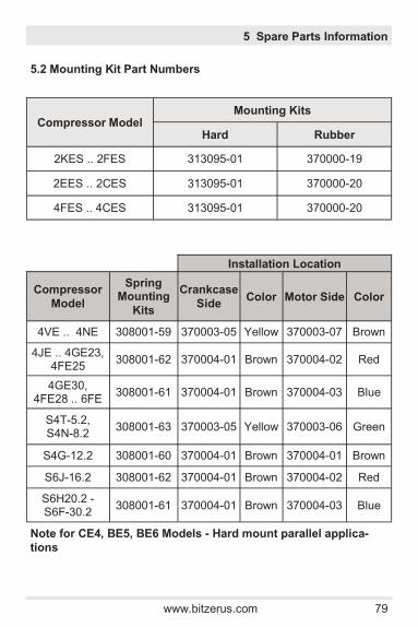
www.bitzerus.com 79
5.2 Mounting Kit Part Numbers
5 Spare Parts Information
Note for CE4, BE5, BE6 Models - Hard mount parallel applica-
tions
Compressor Model Mounting Kits
Hard Rubber
2KES .. 2FES 313095-01 370000-19
2EES .. 2CES 313095-01 370000-20
4FES .. 4CES 313095-01 370000-20
Installation Location
Compressor
Model
Spring Mounting
Kits
Crankcase
Side Color Motor Side Color
4VE .. 4NE 308001-59 370003-05 Yellow 370003-07 Brown
4JE .. 4GE23, 4FE25
308001-62 370004-01 Brown 370004-02 Red
4GE30, 4FE28 .. 6FE
308001-61 370004-01 Brown 370004-03 Blue
S4T-5.2, S4N-8.2
308001-63 370003-05 Yellow 370003-06 Green
S4G-12.2 308001-60 370004-01 Brown 370004-01 Brown
S6J-16.2 308001-62 370004-01 Brown 370004-02 Red
S6H20.2 - S6F-30.2
308001-61 370004-01 Brown 370004-03 Blue

80 www.bitzerus.com
5 Spare Parts Information
5.3 Oil Pump, Valve Plate, Terminal Box Kit, Terminal Plate Kit, Complete Gasket Set Part Numbers
Co
mp
resso
r
Mo
de
l #
Oil P
um
p
Valv
e P
late
(w/ G
askets
)
Term
ina
l
Bo
x K
it
Term
ina
l P
late
Kit
C
om
ple
te
Gasket
Set
2K
ES
N
/A
304055-0
4
343509-0
1
345
50
0-1
6 /
37
29
38
-10
372834-0
1
2JE
S
N/A
304055-0
5
343509-0
1
345
50
0-1
6 /
37
29
38
-10
372834-0
2
2H
ES
N
/A
304055-0
4
343509-0
1
345
50
0-1
6 /
37
29
38
-10
372830-0
1
2G
ES
N
/A
304055-0
2
343509-0
1
345
50
0-1
6 /
37
29
38
-10
372830-0
2
2F
ES
N
/A
304055-0
3
343502-4
1
345
50
0-1
6 /
37
29
38
-10
372830-0
3
2E
ES
N
/A
304059-1
0
343502-4
1
343428-0
1-3
LD
372835-0
1
2D
ES
N
/A
304059-1
1
343502-4
1
343428-0
1-3
LD
372835-0
2
2C
ES
N
/A
304059-1
2
343502-4
1
343428-0
1-3
LD
372835-0
3
4F
ES
N
/A
304059-0
9
343502-4
1
345507-0
6 (
3LD
) 372835-0
4
4E
ES
N
/A
304059-1
0
343502-4
1
345507-0
6 (
3LD
) 372835-0
5
4D
ES
N
/A
304059-1
1
343502-4
1
345507-0
6 (
3LD
) 372835-0
6
4C
ES
N
/A
304059-1
2
343502-4
1
345507-0
6 (
3LD
) 372835-0
7
4V
E
362503-0
1
304063-2
8
308002-5
8
345507-0
2 (
9LD
) 372841-0
4
4T
E
362503-0
1
304063-2
9
308002-5
8
345507-0
2 (
9LD
) 372841-0
3
4P
E
362503-0
1
304063-3
0
308002-5
8
345507-0
2 (
9LD
) 372841-0
2
4N
E
362503-0
1
304063-3
1
308002-5
8
345507-0
2 (
9LD
) 372841-0
1
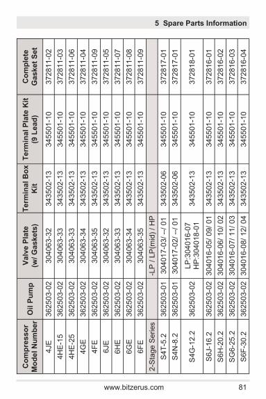
www.bitzerus.com 81
5 Spare Parts Information
Co
mp
resso
r
Mo
de
l N
um
be
r O
il P
um
p
Valv
e P
late
(w/ G
askets
)
Term
ina
l B
ox
Kit
Term
ina
l P
late
Kit
(9 L
ead
)
Co
mp
lete
Gasket
Set
4JE
362503-0
2
304063-3
2
343502-1
3
345501-1
0
372811-0
2
4H
E-1
5
362503-0
2
304063-3
3
343502-1
3
345501-1
0
372811-0
3
4H
E-2
5
362503-0
2
304063-3
3
343502-1
3
345501-1
0
372811-0
6
4G
E
362503-0
2
304063-3
4
343502-1
3
345501-1
0
372811-0
4
4F
E
362503-0
2
304063-3
5
343502-1
3
345501-1
0
372811-0
9
6JE
362503-0
2
304063-3
2
343502-1
3
345501-1
0
372811-0
5
6H
E
362503-0
2
304063-3
3
343502-1
3
345501-1
0
372811-0
7
6G
E
362503-0
2
304063-3
4
343502-1
3
345501-1
0
372811-0
8
6F
E
362503-0
2
304063-3
5
343502-1
3
345501-1
0
372811-0
9
2-S
tage S
eries
-L
P / L
P(m
id)
/ H
P
S4T
-5.2
362503-0
1
304017-0
3/ --
/ 01
343502-0
6
345501-1
0
372817-0
1
S4N
-8.2
362503-0
1
304017-0
2/ --
/ 01
343502-0
6
345501-1
0
372817-0
1
S4G
-12.2
362503-0
2
LP
:304016-0
7
HP
:304018-0
1
343502-1
3
345501-1
0
372818-0
1
S6J-1
6.2
362503-0
2
304016-0
5/
09/ 01
343502-1
3
345501-1
0
372816-0
1
S6H
-20.2
362503-0
2
304016-0
6/
10/ 02
343502-1
3
345501-1
0
372816-0
2
SG
6-2
5.2
362503-0
2
304016-0
7/
11/ 03
343502-1
3
345501-1
0
372816-0
3
S6F
-30.2
362503-0
2
304016-0
8/
12/ 04
343502-1
3
345501-1
0
372816-0
4
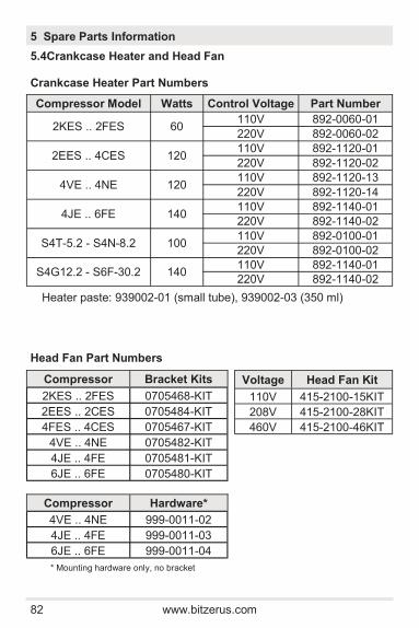
82 www.bitzerus.com
5.4Crankcase Heater and Head Fan
Crankcase Heater Part Numbers
Compressor Bracket Kits 2KES .. 2FES 0705468-KIT 2EES .. 2CES 0705484-KIT
4FES .. 4CES 0705467-KIT 4VE .. 4NE 0705482-KIT
4JE .. 4FE 0705481-KIT 6JE .. 6FE 0705480-KIT
5 Spare Parts Information
Compressor Model Watts Control Voltage Part Number
2KES .. 2FES 60 110V 892-0060-01
220V 892-0060-02
2EES .. 4CES 120 110V 892-1120-01
220V 892-1120-02
4VE .. 4NE 120 110V 892-1120-13
220V 892-1120-14
4JE .. 6FE 140 110V 892-1140-01
220V 892-1140-02
S4T-5.2 - S4N-8.2 100 110V 892-0100-01
220V 892-0100-02
S4G12.2 - S6F-30.2 140 110V 892-1140-01
220V 892-1140-02
Voltage Head Fan Kit 110V 415-2100-15KIT 208V 415-2100-28KIT 460V 415-2100-46KIT
Compressor Hardware* 4VE .. 4NE 999-0011-02
4JE .. 4FE 999-0011-03
6JE .. 6FE 999-0011-04
* Mounting hardware only, no bracket
Head Fan Part Numbers
Heater paste: 939002-01 (small tube), 939002-03 (350 ml)

www.bitzerus.com 83
6.1 Operating Temperatures and Oil Guidelines
Guide values for operating temperatures*
*Values in practice depend much on operating conditions (A/C, medi-
um temp., low temp.) and refrigerant! Please check individual cases
with the selection software or BITZER.
Note: Compressor/Oil Pump rotates in both directions.
Guide values for oil maintenance
**Oil heater recommended.
6 Preventive Maintenance / Service
Operating Temperatures
Suction gas superheat min. ~15°F
typical 20-30°F
Discharge gas temperature min.
40°F above condensing temp. (50° F for R22)
max. 250°F; measured at discharge line
2 Stage Intermediate (middle) pressure superheat
min. ~40°F+subcooler saturation temp;
measured at bulb on MP line
Oil Guidelines
Oil temperatures - on Start-up**
typical 25-35°F above ambient
Oil temperatures - Operating
min. 95°F (min. 55°F > SST)
max. 170°F
Oil pressure differential min. 9.5 ± 2 psi (see p. 69 - 70 for oil
monitoring devices)
Oil change Every 3 years or 10000 hrs of
operation
Note: When changing oil, remove the oil strainer to inspect and clean.

84 www.bitzerus.com
6.2 Switching Frequency and Vibrations
Vibrations on the high pressure side
Vibrations on the high pressure side of refrigeration systems are
mainly caused by: Pulsations, Structure-borne vibrations, Frame
design / basement
Pulsations
Pulsations (longitudinal gas vibrations on the high pressure side) are
created by the discharge process of the gas out of the cylinders.
Their amplitude and frequency depend on:
Compressor speed
Number of cylinders
Cylinder alignment
Refrigerant properties (pressure, temperature and sonic speed)
Critical discharge gas vibrations can be found if the frequency of the
oscillating gas column in a straight discharge tube section gets into
resonance with the natural frequency of the pipework. In the worst
case this could result in a fracture of the piping. The length of the
pipe segment with a resonance frequency corresponding to the natu-
ral frequency of the gas flow is designated as "critical pipe length".
6 Preventive Maintenance / Service
Switching frequency and minimum running time
Nominal Motor
(HP) Starts per hour
Minimum running
time (min)
recommended maximum
up to 7.5 10 20 2
up to 20 8 12 3
above 20 6 6 5
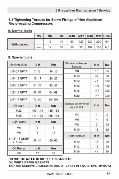
www.bitzerus.com 85
6.3 Tightening Torques for Screw Fixings of Non-Aluminum Reciprocating Compressors
A. Normal bolts
M5 M6 M8 M10 M12 M16 M20 Units
With gasket ---- 16 40 80 125 220 220 Nm
---- 12 30 59 92 162 162 lb ft
B. Special bolts
Sealing plugs lb ft Nm
1/8"-27 NPTF 7..10 10..13
1/4"-18 NPTF 15..17 20..23
3/8"-18 NPTF 31..35 42..47
1/2"-14 NPTF 47..51 64..69
3/4"-14 NPTF 72..80 98..108
Oil drain lb ft Nm
M22 100..114 135..155
M26 114..129 155..175
Sight glass lb ft Nm
M6 6 8
M6 8 11
1 1/8"-18 UNEF (Thread)
37..44 50..60
Oil Pump lb ft Nm
M8 17 23
Shut-off valve and flanges
lb ft Nm
M8 18 25
M10 37 50
M12 74 100
M16 110 150
M18 147 200
M20 147 200
Screws at terminal lugs at 68F
lb ft Nm
M4 1 2
M6 4 6
M8 7 10
M10 15 20
Rotor screws lb ft Nm
M10 15 20
M12 15 20
M16 44 60
DO NOT OIL METALIC OR TEFLON GASKETS OIL WHITE PAPER GASKETS TIGHTEN SCREWS CROSSWISE AND AT LEAST IN TWO STEPS (50/100%)
6 Preventive Maintenance / Service
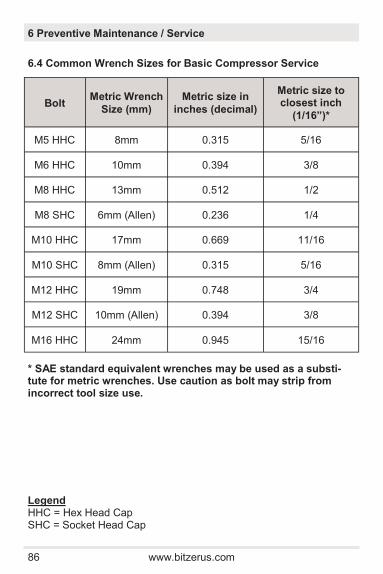
86 www.bitzerus.com
6.4 Common Wrench Sizes for Basic Compressor Service
6 Preventive Maintenance / Service
* SAE standard equivalent wrenches may be used as a substi-tute for metric wrenches. Use caution as bolt may strip from incorrect tool size use.
Bolt Metric Wrench
Size (mm)
Metric size in
inches (decimal)
Metric size to closest inch
(1/16”)*
M5 HHC 8mm 0.315 5/16
M6 HHC 10mm 0.394 3/8
M8 HHC 13mm 0.512 1/2
M8 SHC 6mm (Allen) 0.236 1/4
M10 HHC 17mm 0.669 11/16
M10 SHC 8mm (Allen) 0.315 5/16
M12 HHC 19mm 0.748 3/4
M12 SHC 10mm (Allen) 0.394 3/8
M16 HHC 24mm 0.945 15/16
Legend HHC = Hex Head Cap SHC = Socket Head Cap

www.bitzerus.com 87
6.5 Cylinder head and valve plate replacement guidelines
6 Preventive Maintenance / Service
1. Remove cylinder head bolts. 2. If a capacity regulator (unloader) is installed, remove the bolts
holding the unloader stem as they are part of the cylinder head bolts.
3. Remove the cylinder head. 4. Remove the valve plate and inspect for damage. 5. Install a new valve plate gasket 6. Install a new valve plate. -Note: the new valve plate may look different than the original (number of discharge reeds and diameter of holes may vary) - this is normal and will not affect performance. -Use the dowel/guide pins to align and hold the gasket and valve plate correctly. 6. Install a new head gasket 7. Replace the cylinder head, tighten the screws crosswise and in
at least two steps. Torque the screws to the appropriate force listed on page 78.
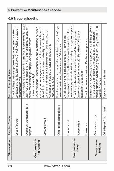
88 www.bitzerus.com
6.6 Troubleshooting
Ob
serv
ati
on
P
ossib
le C
ause
T
rouble
Sh
ooting
Ste
ps
Co
mp
ress
or
is
no
t ru
nn
ing
Loss o
f po
wer
Check v
oltag
e b
etw
een
phases b
efo
re a
nd
aft
er
bre
aker,
conta
cto
r an
d a
t th
e t
erm
inal bo
x. C
heck v
oltage
betw
een
the c
on
tacto
r coil.
Overl
oa
d p
rote
ction (
INT
) tr
ipp
ed
Check r
esis
tance
betw
een M
1 a
nd M
2.
If r
esis
tance is lo
we
r th
an 1
00
0 o
hm
s, re
se
t th
e IN
T.
If t
he r
esis
tan
ce is g
rea
ter,
check m
oto
r w
indin
gs,
sup
ply
volta
ge
and e
nsure
con
nections a
re tig
ht.
Moto
r B
urn
ou
t
Check w
indin
gs. C
heck c
ontin
uity a
nd r
esis
tance
betw
een
win
din
gs. A
ll w
indin
gs s
hould
have t
he s
am
e r
esis
tance o
f abo
ut
1 o
hm
an
d s
ho
uld
sho
w c
ontin
uity.
Als
o c
he
ck
continuity a
nd r
esis
tan
ce b
etw
ee
n e
ach
pin
an
d g
round
. R
esis
tance s
hould
be a
t le
ast
50 M
ega
ohm
s
(n
on
-continu
ous).
Oth
er
pro
tections tri
pp
ed
C
heck c
ontin
uity f
or
all
contr
ol circuit d
evic
es (
e.g
. lo
w/h
igh
pre
ssu
re s
witch
es,
ph
ase loss,
oil
failu
re, e
tc)
Co
mp
ress
or
is
no
isy
Bro
ken r
ee
ds
Check s
uction
and d
isch
arg
e p
ressu
re.
Turn
off t
he
com
pre
sso
r a
nd look fo
r th
e p
ressu
res t
o e
qu
aliz
e.
If t
he
pre
ssu
res e
qualiz
e a
lmost im
media
tely
, cha
ng
e v
alv
e p
late
.
Wet suction
C
heck s
uperh
eat
on t
he
suction
sid
e o
f th
e c
om
pre
ssor
(sup
erh
eat sho
uld
be a
t le
ast
20°
F).
Adju
st T
XV
to t
he
app
ropria
te s
up
erh
eat.
Bro
ken r
od
C
heck fo
r h
eavy v
ibra
tions. R
epla
ce c
om
pre
ssor.
Co
mp
ress
or
lea
kin
g
Gaskets
/ o
-rin
gs
Tig
hte
n b
olts a
cco
rdin
gly
to t
he
to
rque c
hart
. If th
e p
roble
m
is n
ot
solv
ed t
hen c
ha
ng
e th
e g
asket
or
o-r
ing
. In
spe
ct
mating s
urf
aces w
hen
ch
an
gin
g g
askets
. O
nly
use B
ITZ
ER
gaskets
/ o
-rin
gs.
Oil
ad
apte
r / sig
ht
gla
ss
Repla
ce t
he
oil
ada
pte
r.
6 Preventive Maintenance / Service
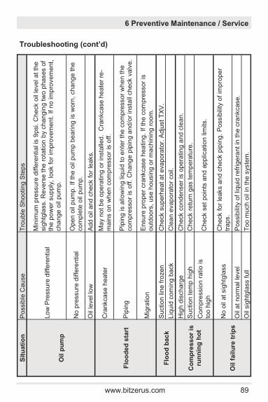
www.bitzerus.com 89
S
itu
ati
on
P
ossib
le C
ause
T
rouble
Sh
ooting
Ste
ps
Oil p
um
p
Lo
w P
ressure
diffe
ren
tial
Min
imum
pre
ssure
diffe
rential is
9psi. C
heck o
il le
vel at th
e
sig
htg
lass. R
evers
e t
he
ro
tation b
y c
ha
ngin
g t
wo p
hases o
f th
e p
ow
er
sup
ply
, lo
ok fo
r im
pro
vem
ent.
If n
o im
pro
vem
ent,
cha
nge
oil
pum
p.
No p
ressure
diffe
rential
Ope
n o
il pum
p.
If t
he o
il pum
p b
eari
ng is w
orn
, cha
ng
e th
e
com
ple
te o
il pum
p.
Oil
level lo
w
Add o
il an
d c
heck fo
r le
aks.
Flo
od
ed
sta
rt
Cra
nkcase h
ea
ter
Ma
y n
ot b
e o
pe
rating o
r in
sta
lled
. C
ran
kcase h
eate
r re
-m
ain
s o
n w
hen
com
pre
ssor
is o
ff.
Pip
ing
P
ipin
g is a
llow
ing liq
uid
to e
nte
r th
e c
om
pre
ssor
whe
n t
he
com
pre
sso
r is
off.
Ch
ang
e p
ipin
g a
nd
/or
insta
ll check v
alv
e.
Mig
ratio
n
Ensure
pro
pe
r cra
nkcase h
ea
ting
. If t
he
com
pre
ssor
is
outd
oo
rs,
use h
ousin
g o
r m
achin
ing r
oom
.
Flo
od
bac
k
Suctio
n lin
e fro
zen
C
heck s
uperh
eat
at
eva
pora
tor.
Adju
st
TX
V.
Liq
uid
com
ing b
ack
Cle
an
evap
ora
tor
coil.
Co
mp
ress
or
is
run
nin
g h
ot
Hig
h d
isch
arg
e
Check c
ond
enser
is o
pera
tin
g a
nd
cle
an.
Suctio
n tem
p h
igh
C
heck r
etu
rn g
as t
em
pera
ture
.
Com
pre
ssio
n r
atio
is
too h
igh
C
heck s
et
poin
ts a
nd a
pplic
ation lim
its.
Oil f
ail
ure
tri
ps
No o
il at sig
htg
lass
Check fo
r le
aks a
nd c
heck p
ipin
g.
Possib
ility
of im
pro
pe
r tr
aps.
Oil
at
no
rmal le
vel
Possib
ility
of liq
uid
refr
ige
rant in
th
e c
rankcase.
Oil
sig
htg
lass f
ull
Too m
uch
oil
in th
e s
yste
m.
Troubleshooting (cont’d)
6 Preventive Maintenance / Service
90 www.bitzerus.com
7 Technical Documentation
Official literature can be found at www.bitzerus.com
Semi Hermetic ECOLINE
Spare Parts
KE-121 SPARE PARTS LIST CE1 - CE3
KE-140 S4T/S4N: 4 CYL OPEN DRIVE AND 2 STAGE (B4)
KE-150 SPARE PARTS LIST B5,B6, S4G - S6F
KE-160 SPARE PARTS LIST C4
Performance Data
KP-109 SEMI-HERMETIC ECOLINE (IP UNITS @ 60Hz )
KP-115 SINGLE STAGE TANDEM (IP UNITS @ 60Hz)
KP-155 2 STAGE (IP UNITS @ 60Hz)
Operating Instructions
KB-104 SEMI HERMETIC ECOLINE
KB-150 2 STAGE (SUPPLEMENT TO KB-104)
Technical and Application Information
KT-100 CAPACITY CONTROL
KT-101 CRII - CAPACITY CONTROL
KT-122 INT SE-B MOTOR OVERLOAD CONTROL
KT-140 ADDITIONAL COOLING - HEAD FANS & WATER COOLED HEADS
KT-150 CRANKCASE HEATING
KT-151 OCTAGON SUPPLEMENT FOR CRANKCASE HEATING
KT-170 OIL PRESSURE CONTROL FOR PUMP MODELS
KT-180 OPTICAL OIL SENSING CONTROL FOR NON-PUMP MODELS
KT-400 PART WINDING MOTOR INFO
KT-410 MOTOR CODE INFO
KT-420 USING FREQUENCY INVERTERS WITH RECIPS
KT-600 COMBINED OR PARALLEL OPERATION WITH RECIPS
KT-601 OCTAGON TANDEM SUPPLEMENT FOR KT-600
KT-602 PARTALLEL COMPOUNDING WITH OCTAGON COMPRESSORS
KW-105 GENERAL TORQUE (IP UNITS)

www.bitzerus.com 91
7 Technical Documentation
Documentation available by contacting BITZER US
Technical Bulletins
TB-0006 OLC-K1 Optical Oil Sensor
TB-0007 BITZER C4 HEATER WELL - FIELD NOTIFICATION
TB-0010 HEAD FAN BRACKETS AND KITS
TB-0011 VARIABLE UNLOADING I (VU CRI)
TB-0028A 3 LEAD TERMINAL PLATE
TB-0028B 6 LEAD TERMINAL PLATE
TB-0028C 9 LEAD TERMINAL PLATE
TB-0033 R22 LOW TEMP APPLICATIONS
TB-0040 VARIABLE SPEED INTALL SETUP
TB-0041 CAPACITY CONTROL MODULES
TB-0043 R407A/F LOW TEMPERATURE APPLICATIONS
TB-0050 VARIABLE UNLOADING II (VU CRII)
Retrofit Documentation
XR-0008 COPELAND TO BITZER CONVERSION GUIDE
XR-0013 CARLYLE TO BITZER CONVERSION GUIDE
XR-0015 COPELAND SCROLLS TO BITZER RECIP CONVERSION GUIDE
Maintenance Bulletin
MB-0030 2NU MOTOR CHECK
Customer Forms
CF-0001 RETURN MATERIAL AUTHORIZATION (RMA) FORM
CF-0015 RECIP SYSTEM INFORMATION REQUEST
CF-0016 2-STAGE SYSTEM INFORMATION REQUIEST

92 www.bitzerus.com
8 System Parameters
Parameter Note
1 Suction Pressure/Temperature Compressor Superheat
2 Discharge Pressure/Temperature Discharge Superheat
3 Oil Temperature
4 Oil Pressure Differential + HP (oil), - LP (crankcase)
5 Ambient Temperature
6 Voltage/Operating current
7 Liquid Temperature Exiting Condenser/subcooler
8 Ambient/Fluid Temperature Condenser
9 Liquid Temperature Before TXV
10 Suction Gas Temperature Exiting Evaporator
11 Air/Fluid Temperature Evaporator

www.bitzerus.com 93
8 System Parameters
In order to properly assist with troubleshooting and tech-nical support, Application Engineers will need as much information related to the compressor operation as pos-sible. Bitzer can provide a form (CF-0015 or CF-0016) to document this information.
Key Compressor Operating Parameters Compressor Superheat (SH): Adequate SH insures that liquid re-frigerant is not returning to the suction side of the compressor. BITZ-
ER recommends 20°F - 30°F of SH at the compressor. SH can be
calculated by subtracting the saturated suction temperature from the return gas temperature (Reference point 1). Discharge Temperature: The discharge temperature should be measure 6” - 8” from the discharge service valve. The max discharge
temperature is 250°F. High (or low) discharge temperatures indicate a compressor or system problem. The BITZER software or technical support can provide normal discharge temperatures. Suction/Discharge Pressure/Temperature: Suction and discharg-es pressures and temperatures at the compressor can be used to determine compressor or system performance and calculate suction and discharge superheats. Oil Pressure Differential: For compressor models with oil pumps, the oil pressure differential is the difference between the high side of the oil pump (label +HP on the pump) and the crankcase pressure (-LP). Oil pump/compressor that are operating normally should have an oil pressure differential of 20 - 50psi. Minimum differential is 9psi. Operating Voltage: When measured during operation, the voltage at each terminal pin should be within 2% of the others and 10% of the compressor nameplate voltage. Operating Current: When measured during operation, the amper-age at each terminal pin should be within 10% of the others.

94 www.bitzerus.com