hillside.nethillside.net/plop/plop2k/proceedings/parssinen/parssinen.pdf · 2 (26) patterns...
TRANSCRIPT

����������������� ������������������
���������������������������������
� ��������
When dealing with the specification, design, or implementation of a communication protocol, com-mon parts can be found. These parts can be specified as design patterns which are independent fromparticular protocol specification, its implementation details, or used implementation language. It is thegoal of this paper to present these parts, which are extracted from protocol specifications, designs, ex-isting implementations, and data communication literature. These patterns provide common principlesfor understanding protocols and their parts, or implementing new ones. This paper can be read as a ba-sic presentation of protocol design and implementation structure, but also advanced readers can getbenefit from it.
In this paper three design patterns for a protocol system architecture are presented. These patternsare tightly related to each other. They are part of a pattern language for protocol implementation whichthe authors have developed during last years.
The Protocol Patterns presented in this paper include the �������������� ������ which models aprotocol system in general level, the ��������������� ������ which models active parts of a system,and the ������������������ ������ which models communication between parts of a protocol system.
A basic model of communication protocol implementation and two implementation frameworksare presented in this paper to give background information. The Unified Modeling Language (UML) isused in the class diagrams of this paper, and the UML pattern notation is used to describe roles of anindividual pattern.
� ����������
Communication protocols specify how two entities can communicate with each other, i.e. what is theset of messages they can interchange and what are the rules that govern message interchange. Whendifferent protocols are investigated common general parts and relations between them can be found.These parts and relations are independent from particular specification, implementation details or usedimplementation language. In this paper we present design patterns for a protocol system architecture.
Understanding of patterns behind a protocol system architecture facilitates creation of a clear, con-sistent, and more understandable architecture which is also efficient to implement and maintain. It fa-cilitates integration of protocol components produced using different implementation frameworks, andhelps developing protocol implementation tools. The patterns presented in this paper are currentlyused to implement code generation tools for a protocol engineering process [1].
These Protocol Patterns are derived by the authors from many different sources including actualprotocol implementations, communication protocol implementation frameworks, existing protocolmodels, and related existing design patterns, including Layers architecture pattern [8].
1 (26)
Copyright © 2000, Juha Pärssinen, Markku Turunen. Permission is granted to copy for the PLoP 2000 conference. All other rights reserved.

Patterns presented here have been used in some forms in communication system engineering for de-cades and their original inventors are unknown as original reasons to take them in use. Because of thispatterns are not presented typical context-forces-solution order, but in context-solution-forces which ismore suitable in this case. In data communication literature solution has a main role, not problems it-self.
This paper contains three main parts: the section 3 "Communication Protocol Structure" on page 3contains background information about communication protocols, the section 4 "Protocol Implementa-tion Frameworks" on page 5 contains information their implementation, and the section 5 "Patterns forProtocol System Architecture" on page 9 contains actual patterns. Advanced reader can jump straightto patterns.
A basic protocol model is presented in the section 3 "Communication Protocol Structure". This isthe model which was used as a starting point to mine for these patterns. During the years many proto-col implementation frameworks are developed to offer efficient and simple way to create and config-ure functionality of common tasks of protocols. These common tasks and two implementationframeworks, Conduits+ [10] and Specification and Description Language (SDL) [14], are presented inthe section 4 "Protocol Implementation Frameworks". These frameworks are used as examples whenwe show how patterns presented in this paper can be implemented. Conduits+ [10] has its roots in ob-ject orientation, and SDL [14] has process oriented background. Other protocol frameworks are alsostudied by authors, but these frameworks or examples which utilize them are not presented here due tothe lack of space.
The patterns presented in the section 5 "Patterns for Protocol System Architecture" are the ������������� ������, the ��������������� ������, and the ������������������ ������. The Protocol Systempattern and the Protocol Entity pattern model static parts of a protocol system, i.e. they are the compo-nents that a system is composed of, what is the structure of the components and how the system com-ponents are interconnected. The Protocol Behavior pattern models actual message exchange betweendifferent parts of a the system.
A simplified TCP/IP stack implementation is used as a running example in this paper. This proto-col stack example contains only TCP and IP protocols, shows parts of their high level behavior andcollaboration, but not any implementation details of them. TCP/IP is explained in many data commu-nication textbooks, including [4]. Implementation details of TCP/IP are explained in [5].
The Unified Modeling Language (UML) is used in the class diagrams of this paper, and the UMLpattern notation from [2] is used to describe roles of an individual pattern.
2 (26)
� ������������������ ��������
Protocol systems offer a multitude of services on differing networks with a number of service options.In order to tackle this complexity, protocol systems are organized as series of subsystems, often calledprotocol layers or protocol entities. Conceptually different responsibilities are separated to differentlayers and implemented separately. As a result there are many benefits compared to the case when theentire protocol is implemented as one monolithic entity.
Each entity is designed to deal with a problem, or a set of problems, in the context of the entire pro-tocol’s functionality, using the services provided to it by the lower-level layers. The entities are inter-connected through well-defined interfaces. Together they form a communications protocol system,often referred to as a protocol stack.
An entity has to be able to communicate with its peer and adjacent entities according to its specifi-cation. To fulfill these requirements an entity has to have interfaces to adjacent entities in the same sys-tem, an interface to its peer, internal data storage facilities for protocol information, and description ofits behavior. In protocol engineering, an interface defines two sets of messages, the set of sent mes-sages and the set of received messages. A entity interface corresponds to an OSI Service Access Point(SAP) [3].
Communication of an entity can be connectionless and/or connection-oriented. A connectionlesscommunication is a simple Request-Response (or just Request) kind of message exchange.
A connection-oriented communication consists of connection establishment, message exchange,and finally disconnection phase. There can be multiple concurrent communications which can be indifferent phases.
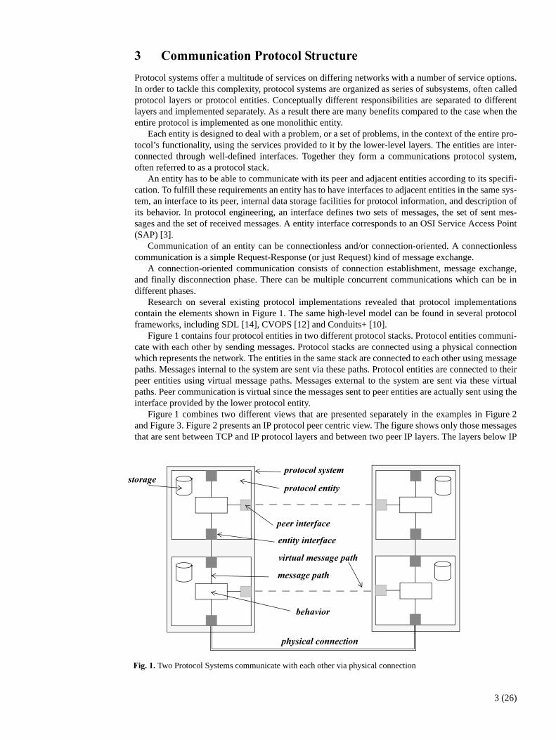
Research on several existing protocol implementations revealed that protocol implementationscontain the elements shown in Figure 1. The same high-level model can be found in several protocolframeworks, including SDL [14], CVOPS [12] and Conduits+ [10].
Figure 1 contains four protocol entities in two different protocol stacks. Protocol entities communi-cate with each other by sending messages. Protocol stacks are connected using a physical connectionwhich represents the network. The entities in the same stack are connected to each other using messagepaths. Messages internal to the system are sent via these paths. Protocol entities are connected to theirpeer entities using virtual message paths. Messages external to the system are sent via these virtualpaths. Peer communication is virtual since the messages sent to peer entities are actually sent using theinterface provided by the lower protocol entity.
Figure 1 combines two different views that are presented separately in the examples in Figure 2and Figure 3. Figure 2 presents an IP protocol peer centric view. The figure shows only those messagesthat are sent between TCP and IP protocol layers and between two peer IP layers. The layers below IP
�!"��"�Two Protocol Systems communicate with each other via physical connection
������������� ���
����� ���
�����������������
�������������
���������
������
�������
�������������
������������
3 (26)

are omitted. This view makes it possible to specify behavior of a protocol only in terms of IP mes-sages.
Figure 3 presents entity interface centric view. Only real interfaces and message paths are shown.Peer communication is hidden inside protocol behavior.
Both views are very useful because they answer different questions. The first one answers the ques-tion “what is the correspondence between internal messages towards entity interface users (TCP incase of IP) and external messages towards peer protocol entities”. The second one answers the ques-tion “how protocol entities within a system communicate with each other”
�!"��"�The Protocol Entity IP send one message to its peer entity using a virtual message path.
IP:Peer Interface
1:
2:3: 4: 5:
6:
7:
TCPtoIP:Entity Interface
IP:Behavior
IPtoTCP:Entity InterfaceIP:Protocol Entity
TCP:Protocol Entity
IP:Behavior
IPtoTCP:Entity Interface
TCPtoIP:Entity Interface
IP:Protocol Entity
TCP:Protocol Entity
:Protocol System :Protocol System
IP:Peer Interface
�!"��"�Protocol Entity IP send one message to its peer entity using a real message path via an external object(Ethernet).
:Ethernet
1:
2:
3:
IP:Behavior
IPtoTCP:Entity Interface
TCPtoIP:Entity Interface
TCP:Protocol Entity
IP:Protocol Entity
4:
:Ethernet
8:
7:
6:
IP:Behavior
IPtoTCP:Entity Interface
TCPtoIP:Entity Interface
TCP:Protocol Entity
IP:Protocol Entity
5:
IPtoEthernet:Enviroment InterfaceIPtoEthernet:Enviroment Interface
:Protocol System :Protocol System
IPtoEthernet:Entity Interface IPtoEthernet:Entity Interface
9:
10:
4 (26)

# ��������$����������� ����%���
���������������������������������������� ���������������������� ������������������������������������������������������������������ !�
In a protocol implementation there are functionality that are always needed to be implemented. Imple-mentation of statemachines of protocol entities, communication between protocol entities within thesame system and between peer entities are common tasks that everyone working with protocols hasencountered. Protocol implementation frameworks offer efficient and simple way to create and config-ure functionality of these common tasks. They also usually offer support for low level implementationissues like timers, memory management, and scheduling.
During the last decades many different frameworks and languages for protocol implementationhave been developed. Next in this section two of them are described briefly. Conduits+ [10] has itroots in object orientation and it is implemented using design patterns from [7]. Specification and De-scription Language (SDL) [14] is a language that can be used when modeling communicating systems.SDL systems can be defined using either graphical or textual representation. It has process orientedbackground, but there are currently ongoing work to add object-oriented features to SDL.
#"� �������&
The Conduits+ is a protocol implementation framework. Its ancestor, the Conduits framework, was de-signed by Jonathan Zweig in his Master’s Thesis [11]. It was used to implement the TCP/IP stack. Theframework was later improved by Hüni et al and it was then named Conduits+ [10]. In this section thegraphical symbols and the roles of different conduits conform to the Conduits+ [10].
A Conduits+ framework consists of two basic elements, conduits and information chunks or mes-sages. The conduits can be connected to each other creating a conduit graph that represents the actualprotocol stack. Messages represent the information flowing through the stack.
There are four different conduits - Protocol, Mux, ConduitFactory and Adapter. The roles and re-sponsibilities of the different conduits are as follows:• A Protocol conduit is the heart of a protocol layer implementation. It encapsulates the behavior of a
protocol, i.e. the reactions to incoming messages at a given time.• A Mux conduit multiplexes messages from several conduits to a single one and vice versa. For ex-
ample in case of a connection-oriented protocol a mux routes incoming messages to the correctconnection handling Protocol conduit.
�!"�#"�Conduits+ class diagram
AdapterMessage
Transporter
<<Abstract>>Visitor Side
InformationChunk
Mux
Protocol
ConduitFactory
<<Abstract>>Conduit
SideB
SideA
<<Abstract>>State
ConcreteStateNConcreteState1
1
traverses
11
triggers
carriescarries
{if Adapter 0, if ConduitFactory 1, if Mux 1..nif Protocol 1}
0..n
1
1 * *
1,2 1
Messenger
5 (26)

• A ConduitFactory creates new instances of conduits for example to handle a new communicationsession.
• An Adapter conduit is used as an interface to the world outside of a conduits graph, like some othersoftware or hardware.
A conduit is a subclass of the Conduit base class and has capabilities to both interconnect with otherconduits, and handle incoming messages. A conduit has two distinct connection points, Side A andSide B. Two conduits can be connected to each other by connecting their sides. Messages are sent andreceived via these connection points. Messages are carried by MessageTransporters, and they traversethe conduit graph and can trigger actions in the conduits. The class diagram of the Conduits+ is shownin Figure 4.
One example of a simple TCP/IP protocol implementation using the Conduits+ is shown inFigure 5. In this figure there are two Adapters to connect conduits graph to Ethernet and to SocketAPI(TCP/IP socket application programming interface), two Muxes to handle connection-oriented socketcommunication of the TCP, and single Protocol conduit to handle all connectionless communication ofthe IP protocol. In Conduits+ one can not separate protocol layers, or entities, by encapsulating se-lected conduits within other structures. In Figure 5 additional notation is used to guide a reader andmake easier for him or her to see the protocol entity boundaries.
Behavior of a protocol entity is implemented in a Protocol conduit. Behavior can be described as afinite state automaton that remembers the current state of communication and that receives, creates andresponds to the control messages or the messages sent by its peer protocol entity. It also supplies addi-tional services, such as counters, timers and storage, e.g. for partially received protocol messages.Events to a Protocol conduit are sent as Messengers which carried by MessageTransporters. InFigure 5 one Protocol conduit handles one socket in the TCP.
The role of a Mux is to route incoming messages to a proper receiver. When an incoming messagerequires a new connection then a Mux must request a ConduitFactory to create a new conduit to handlethe incoming message. A Mux is used to handle multiple simultaneous sessions on a single protocollayer. In Figure 5 Muxes routes an incoming message to a proper Protocol conduit, i.e. TCPSocket, inthe TCP.
ProtocolProtocolTCPSocket:Protocol
�!"�'"�Simplified TCP/IP protocol stack using the Conduits+ implementation framework
SocketAPI:Adapter
:Mux
:Mux
:ConduitFactory
Ethernet:Adapter
sideA
sideA
sideA
sideAsideA
sideB
sideA
sideB
sideB[...]
sideB[...]sideB[0]
sideB[0]
creates
IP:Protocol
sideA
sideB
TCP
IP
�������������
�������������
��� ��
��������
�����������������
6 (26)

An Adapter is used as an interface to some other software or hardware. Thus the Adapters are the end-points in the conduit graph.
The Conduits+ framework uses widely design patterns from [7]. An example of design patterns isthe Visitor pattern [7] which is used to decouple Messengers from conduits. Visitors are responsiblefor the traversal on the conduit graph and the Messengers only trigger actions. Another example is theProtocol conduit which uses the modified State pattern [7]. For more details on the used design pat-terns please see the original Conduits+ paper [10]
#"� $��������������(�����$����)��!��!��* ()+
Specification and Description Language (SDL) is a standard language for specification and descriptionof communicating systems. It is currently developed by ITU-T and is defined in the Z.100 recommen-dation [14]. There are several SDL versions. The first recommendation was released in 1976, followedby further releases once in every four years. In the 1988 version the language was given a formal basisand reached a mature status as a Formal Description Technique. The 1992 version was a major im-provement introducing among other things object orientation. There are currently ongoing task to de-velop SDL2000 which contains even more object-oriented features.
An SDL system can be defined using either graphical or textual representation. The graphical rep-resentation makes SDL more user-friendly and easier to understand while the textual representationwas originally planned as an interchange format.
Currently SDL has a dual role as a specification language and also as an implementation language.In this paper we concentrate on the implementation language aspect. There are SDL tools that providenecessary features so that they can be used as protocol implementation frameworks.
An SDL system consists of blocks which can communicate with each other and with the environ-ment surrounding the system by sending signals. In Figure 6 the system consist of two blocks TCP andIP. The blocks correspond to protocol layers. Inner structure of the TCP block is shown in Figure 7,and the IP block in Figure 8. Communication between the blocks is done via channels. Signal lists as-sociated with the channels list the signals that are allowed to be sent to a given direction.
�!"�,"�TCP and IP layers in a protocol stack
[(TCPToSocketAPISignals)]
[(SocketAPIToTCPSignals)]
SocketAPIToTCPChannel
[(IPToTCPSignals)]
TCPToIPChannel[(TCPToIPSignals)]
System TCP_IP
[(EthernetToIPSignals)]
[(IPToEthernetSignals)]
IPToEthernetChannel
TCP
IP
1(2)
����������������
������
����
7 (26)
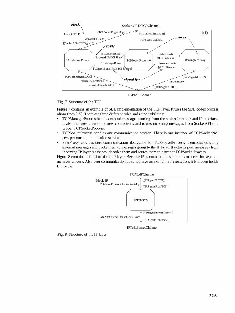
Figure 7 contains an example of SDL implementation of the TCP layer. It uses the SDL codec processidiom from [15]. There are three different roles and responsibilities:• TCPManagerProcess handles control messages coming from the socket interface and IP interface.
It also manages creation of new connections and routes incoming messages from SocketAPI to aproper TCPSocketProcess.
• TCPSocketProcess handles one communication session. There is one instance of TCPSocketPro-cess per one communication session.
• PeerProxy provides peer communication abstraction for TCPSocketProcess. It encodes outgoingexternal messages and packs them to messages going to the IP layer. It extracts peer messages fromincoming IP layer messages, decodes them and routes them to a proper TCPSocketProcess.
Figure 8 contains definition of the IP layer. Because IP is connectionless there is no need for separatemanager process. Also peer communication does not have an explicit representation, it is hidden insideIPProcess.
�!"�-"�Structure of the TCP
SocketAPIToTCPChannel
TCPToIPChannel
TCPManagerProcess TCPSocketProcess (0,) RoutingPeerProxy
[(TCPDataSignalsUp)]
[(PDUSignals)]
[(PDUSignals)][(SocketAPIToTCPSignals)]
[(ControlSignalsToIP)]
[(TCPCtrlIndSignalsDown)]
[(SocketAPItoTCPSignals)]
[(TCPControlSignalsUp)]
[(DataSignalsToIP)]
[(DataSignalsfromIP)]
[(ControlSignalsFromTCPSocket)]
TCPSocketUpRoute
IPDataRoute
ManagerUpRoute
ManagerDownRoute
ToPeerRoute
FromPeerRoute
ToTCPSocketRoute
ToManagerRoute
Block TCP 1(1) �����
����
�����������
�����
�!"�."�Structure of the IP layer
TCPToIPChannel
[(IPSignalsToTCP)]
[(IPSignalsFromTCP)]
[(IPSignalsToEthernet)]
[(IPSignalsFromEthernet)]
IPDataAndControlChannelRouteUp
IPDataAndControlChannelRouteDown
IPToEthernetChannel
IPProcess
Block IP
8 (26)

' ����������������� ������������������
The common general parts and relations in different protocols can be identified and described as de-sign patterns [7]. In this section three patterns for protocol system architecture are presented. Thesepatterns are tightly related to each other, and are part of a pattern language for protocols.
The patterns presented in this paper are the ������������� pattern, the �������������� pattern,and the ����������������� pattern. The Protocol System pattern and the Protocol Entity pattern modelstatic parts of a protocol system, i.e. which are the components that a system is composed of, what isthe structure of the components and how the system components are interconnected. The Protocol Be-havior pattern models actual message exchange between different parts of the system. These three pat-terns can be considered as a an architectural patterns [8].
The design pattern format used here is a modification of several existing ones. The main modifica-tion is the order of the parts of pattern description: forces are presented after context and solution. Thereason for this is simple. Patterns presented here have been used in communication system engineeringfor decades and their original inventors are unknown as original reasons to take them in use.
The Layers architecture pattern [8] is closely related to these patterns. However, in the ProtocolSystem pattern, Protocol Entities, or layers, don’t have to be adjacent. These patterns also describemore inner details than the Layers pattern.
������ �����
����/� A communication system is composed of three parts: a user, a communication protocol system, and acommunication media (i.e. environment or hardware). A communication system acts as a mediator be-tween the user and the environment. The user is interested in very high-level aspects of communica-tion, and the environment is offering only low-level communication services. If there are changes insystem or environment, the user doesn’t want to know it. He or she wants just to use his or her applica-tion above the communication system.
The communication system is typically specified as adjacent layers [3][8], or entities, with twotypes of interfaces: peer interface and entity interface. Some of these interfaces are standardized insome acceptance level: de-facto, de-jure etc. An interface between peer entities is always standardizedwhereas interface between entities in the same system is rarely standardized. However, there is often arecommended or informal entity interface.
����� The Protocol System pattern is the highest level pattern in the pattern language for protocol system. Itencapsulates the whole protocol system, and forms the basis of other protocol patterns. It describes aprotocol system structure in high level by specifying what are the components that a system is com-posed of, and how they are interconnected to each other. The Protocol System pattern models a proto-col system by specifying:• what are the components that a system is composed of,• which are responsibilities of the components,• how the components are interconnected, and• how a system communicates with its environment.The roles of Protocol System pattern are �������������, ��������������, ������"��������, and �������������"��������, as shown in Figure 9.
�!"�0"�The roles of Protocol System Pattern
Protocol System
Entity InterfaceEnvironment Interface
Protocol SystemProtocol Entity
9 (26)
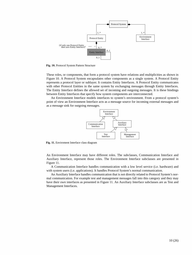
These roles, or components, that form a protocol system have relations and multiplicities as shown inFigure 10. A Protocol System encapsulates other components as a single system. A Protocol Entityrepresents a protocol layer or sublayer. It contains Entity Interfaces. A Protocol Entity communicateswith other Protocol Entities in the same system by exchanging messages through Entity Interfaces.The Entity Interface defines the allowed set of incoming and outgoing messages. It is these bindingsbetween Entity Interfaces that specify how system components are interconnected.
An Environment Interface models interfaces to system’s environment. From a protocol system’spoint of view an Environment Interface acts as a message source for incoming external messages andas a message sink for outgoing messages.
An Environment Interface may have different roles. The subclasses, Communication Interface andAuxiliary Interface, represent those roles. The Environment Interface subclasses are presented inFigure 11.
A Communication Interface handles communication with a low level service (i.e. hardware) andwith system users (i.e. applications). It handles Protocol System’s normal communication.
An Auxiliary Interface handles communication that is not directly related to Protocol System’s nor-mal communication. For example test and management messages fall into this category and they mayhave their own interfaces as presented in Figure 11. An Auxiliary Interface subclasses are as Test andManagement Interfaces.
�!"��1"�Protocol System Pattern Structure
Protocol System
1..*1..*
EnvironmentInterfaceProtocol Entity
Entity Interface
0..*{if only one Protocol Entity
then zero Entity Interface}
0..1
0..1
�!"���"�Enviroment Interface class diagram
EnvironmentInterface
CommunicationInterface
AuxiliaryInterface
TestInterface
ManagementInterface
10 (26)

One example of Protocol System pattern use is shown as a Object Diagram in Figure 12 on page 11. Inthis figure a simplified TCP/IP protocol stack is presented. Between TCP and IP layers there are entityinterfaces for them, and Environment Interfaces to the SocketAPI and the Ethernet.
���� Patterns presented here have been in practical use in communication system engineering for decadesand their original inventors are unknown as original forces which lead to these.
Communication systems are specified using adjacent layers using OSI reference model [3] or otherlayer models. Layers are build on top of each other, higher layer uses interface, or service access point(SAP), provided by lower layer [3]. The use of interface hides lower layer from layers above it. Thismodularity and encapsulation of entities, which have been in use years before advent of object-ori-ented programming, serve three related goals:• organization of standardization effort,• modular, component based, implementation, testing and maintenance process, and• transparent and reliable system for user.These three cases are main sources of forces of this pattern. Effort of standardization organizationbrings following forces:1. Some parts of a protocol system are standardized and some are not. An interface between peers
is always standardized. Standardized interface is often called a normative interface. Interfacebetween entities in the same system is not always standardized, but there is often a recom-mended or informal interface. This recommended interface is often called as a non-normativeinterface.
2. An interface in standardization terms means detailed specification of incoming and outgoingmessages. Interface in object-orientation means only incoming messages (i.e. method calls).
Realization of modular implementation, testing, and maintenance process brings following forces:1. Time to market is short. When a standard (in some acceptance level; de-facto/de-jure etc.) is
published there is relatively short time to make a product. In normal case companies participatestandardization process to get early information and to have effect on the standard.
2. Testing of a communication system is complicated. In normal case there are more possiblecombinations of message exchange than it is feasible to test.
3. Implementation of complicated communication software is slow and error-prone. 4. Parts of a protocol system are legacy and they are implemented using some old technology. Re-
use of old existing parts is used to improve implementation time and save old investments.5. Maintenance and updating of a protocol system must be easy and low cost.
�!"���"�Simplified TCP/IP protocol Stack implemented using the Protocol System pattern - an object diagram.
SocketAPI:Communication Interface
IPtoTCP:Entity Interface
TCPtoIP:Entity Interface
TCPtoIP:Entity Interface
TCP:Protocol Entity
IP:Protocol Entity
IPtoEthernet:Communication Interface
IPtoEthernet:Entity Interface
TCPIP:Protocol System
11 (26)

6. The implementation of a system is quicker and less error-prone if used implementation language orplatform support repetitive tasks of protocol system implementation.
Transparent and reliable communication system for user brings following forces:1. There is a big gap between a user of a protocol system and a environment, or hardware, which a
communication system should fill. If there are changes in environment, the user doesn’t want toknow it. He or she wants just to use his or her application above the communication system.
2. A protocol system has to be robust. A protocol system has to work long time without any de-fect. It should also recover almost all possible defects automatically and notify this to mainte-nance. A protocol system should never loose any important data. One example of importantdata is accounting information for an operator.
3. The communication media (i.e. environment) is not always reliable.4. A protocol implementation has to be as efficient as possible. Especially video conference and
other real-time multimedia applications are very sensitive for even small delays. However, inmobile computing communication is usually bounded by wireless network, not protocol itself.
The Protocol System pattern is used to balance these forces together with other patterns in this lan-guage.
2/��$��� Following section contains implementation examples of the Protocol System pattern using Conduits+[10] and SDL [14]. These are described briefly with simplified TCP/IP protocol example from the sec-tion 4 "Protocol Implementation Frameworks". This section uses figures from that section.
���������
There is not one distinct Protocol System component in the Conduits+ framework. Parts of system, theconduits, are bind together when a system is initialized. The Figure 5 on page 6 contains a simplifiedTCP/IP protocol System example. Even if there is a conceptual separation between TCP and IP layercomponents (shown as a dashed box) from Conduits+ point of view there is no difference between theconduits in the TCP and IP layers. Also the Protocol Entity component is purely conceptual. A Proto-col Entity consists of at least one Protocol conduit and any number of Muxes and ConduitFactories. Inthe Figure 5 the conduits inside the TCP box belong to one Protocol Entity and the conduit inside theIP box belong to another.
The Adapter conduit provides all the different Environment Interfaces and is the only way to attach theconduit graph to the environment.
The sides of conduits are used to connect conduits and thus are one part the Entity Interfaces in theConduits+ framework. However, a set of Messengers is used to define all possible incoming and out-going events of a Protocol Entity, and thus are other part of Entity interfaces.
�!"���"�Protocol System Pattern related Conduits+ classes
Mux*
Protocol1..*
Adapter1..*
ConduitFactory*
<<Abstract>>Conduit*
Side
SideB*
SideA1
Messenger*
12 (26)
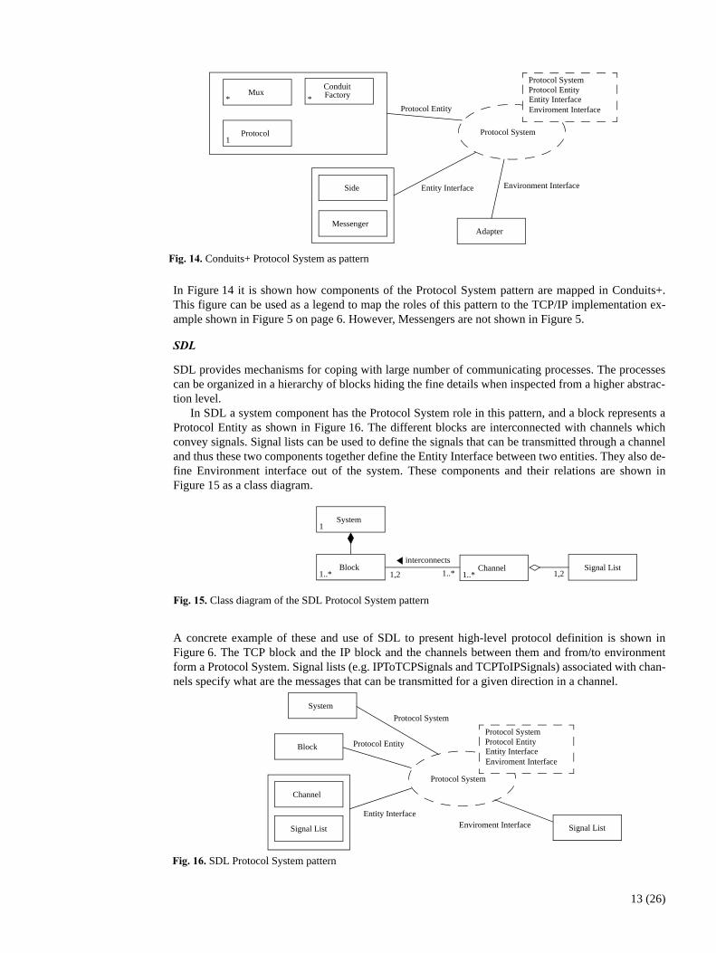
In Figure 14 it is shown how components of the Protocol System pattern are mapped in Conduits+.This figure can be used as a legend to map the roles of this pattern to the TCP/IP implementation ex-ample shown in Figure 5 on page 6. However, Messengers are not shown in Figure 5.
��
SDL provides mechanisms for coping with large number of communicating processes. The processescan be organized in a hierarchy of blocks hiding the fine details when inspected from a higher abstrac-tion level.
In SDL a system component has the Protocol System role in this pattern, and a block represents aProtocol Entity as shown in Figure 16. The different blocks are interconnected with channels whichconvey signals. Signal lists can be used to define the signals that can be transmitted through a channeland thus these two components together define the Entity Interface between two entities. They also de-fine Environment interface out of the system. These components and their relations are shown inFigure 15 as a class diagram.
A concrete example of these and use of SDL to present high-level protocol definition is shown inFigure 6. The TCP block and the IP block and the channels between them and from/to environmentform a Protocol System. Signal lists (e.g. IPToTCPSignals and TCPToIPSignals) associated with chan-nels specify what are the messages that can be transmitted for a given direction in a channel.
�!"��#"�Conduits+ Protocol System as pattern
Mux*
Protocol1
Adapter
ConduitFactory*
Side
Protocol Entity
Environment Interface
Protocol System
Entity InterfaceEnviroment Interface
Protocol SystemProtocol Entity
Entity Interface
Messenger
�!"��'"�Class diagram of the SDL Protocol System pattern
Block1..*
Channel1..*
interconnects
1,2 1..*
System1
Signal List1,2
�!"��,"�SDL Protocol System pattern
Protocol System
Protocol Entity
Enviroment Interface
Block Entity InterfaceEnviroment Interface
Protocol SystemProtocol Entity
Signal List
Entity Interface
System
Protocol System
Signal List
Channel
13 (26)
In Figure 16 it is shown how components of the Protocol System pattern are mapped in SDL. This fig-ure can be used as a legend to map the roles of this pattern to the simplified TCP/IP implementationexample shown in Figure 6 on page 7.
����3������ The Protocol System pattern has several advantages, but it also contains a few disadvantages. Theseare quite similar as in the Layers architecture pattern [8].
���������• Reuse of Protocol Entities. If an individual entity embodies a well-defined abstraction and has a
well-defined and documented interface, the entity can be reused in multiple context.• Support for standardization. Clear-defined and commonly-accepted levels of abstraction facilitates
of standardized tasks and entity interfaces. Different implementations of the same entity interfacecan be interchanged.
• Dependencies are kept local. Standardized entity interfaces between layers usually confine the ef-fect of code changes to the Protocol Entity that is changed. Changes in the environment affect onlyEnvironment Interface in concern.
• Exchangeability. Individual Protocol Entity implementations can be replaced by semanticallyequivalent implementations without great effort.
������������• Cascades of changing behavior. Entities can often be shielded from changes in other entities. How-
ever sometimes a change ripples from one entity to all others. In this case the Protocol System pat-tern becomes a disadvantage if a substantial amount of rework has to be done on many entities toincorporate an apparently local change.
• Lower efficiency. An architecture, which is implemented using the Protocol System pattern, is usu-ally less efficient than a monolithic implementation. This is result from the large number of opera-tions and transformations the message flow experiences when it passes thought the entities.
• Unnecessary work. Some services performed by previous entities may not needed by adjacent enti-ties. This has of course a negative impact on performance.
������ The Layers architecture pattern [8] is closely related to this pattern. However, in the Protocol Systempattern, Protocol Entities don’t have to be adjacent. These patterns also describe more inner detailsthan the Layers pattern.
���$����� The following artifacts and people have inspired the authors:• Layers architecture pattern [8],• lectures of professor Olli Martikainen from Helsinki University of Technology,• work with many protocol implementation frameworks, including Conduits+ [10], SDL [14], and
CVOPS [12],• many protocol implementations, including TCP/IP and GSM,• numerous data communication text books, especially [3], and • our shepherd, Michael Stal, and participants of PLoP2000 “network of learning” -workshop.
������ Juha Pärssinen, Markku Turunen
������2�����
����/� Communication systems are typically organized as a series of layers or entities. An entity is capable ofsending or receiving information, and it has an inner state during communication. An entity has a vir-tual message path to its peer entity (see Figure 2 on page 4), and real message paths to its adjacent en-tity (see Figure 3 on page 4) or environment as shown in Figure 1.
The Protocol Entity pattern can be used as a compositional part of the Protocol System pattern. Itcan behave as a layer in the Layers architecture pattern [13].
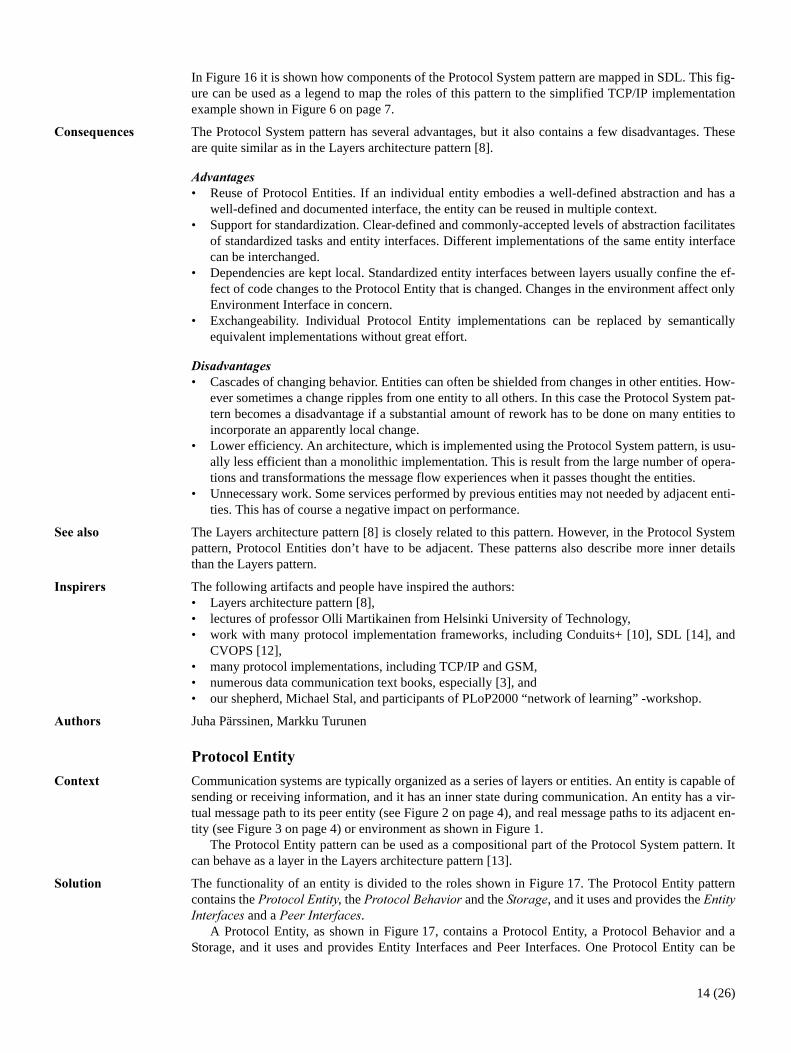
����� The functionality of an entity is divided to the roles shown in Figure 17. The Protocol Entity patterncontains the ��������������, the ����������������� and the �������, and it uses and provides the �����"�������� and a �����"��������.
A Protocol Entity, as shown in Figure 17, contains a Protocol Entity, a Protocol Behavior and aStorage, and it uses and provides Entity Interfaces and Peer Interfaces. One Protocol Entity can be
14 (26)
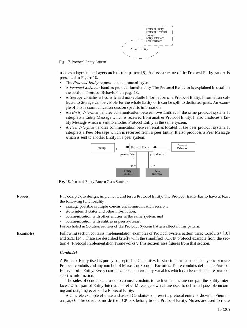
used as a layer in the Layers architecture pattern [8]. A class structure of the Protocol Entity pattern ispresented in Figure 18.• The �������������� represents one protocol layer. • A ����������������� handles protocol functionality. The Protocol Behavior is explained in detail in
the section “Protocol Behavior” on page 18.• A ������� contains all volatile and non-volatile information of a Protocol Entity. Information col-
lected to Storage can be visible for the whole Entity or it can be split to dedicated parts. An exam-ple of this is communication session specific information.
• An ������"�������� handles communication between two Entities in the same protocol system. Itinterprets a Entity Message which is received from another Protocol Entity. It also produces a En-tity Message which is sent to another Protocol Entity in the same system.
• A �����"�������� handles communication between entities located in the peer protocol system. Itinterprets a Peer Message which is received from a peer Entity. It also produces a Peer Messagewhich is sent to another Entity in a peer system.
���� It is complex to design, implement, and test a Protocol Entity. The Protocol Entity has to have at leastthe following functionality:• manage possible multiple concurrent communication sessions,• store internal states and other information,• communication with other entities in the same system, and • communication with entities in peer systems.Forces listed in Solution section of the Protocol System Pattern affect in this pattern.
2/��$��� Following section contains implementation examples of Protocol System pattern using Conduits+ [10]and SDL [14]. These are described briefly with the simplified TCP/IP protocol example from the sec-tion 4 "Protocol Implementation Frameworks". This section uses figures from that section.
����������
A Protocol Entity itself is purely conceptual in Conduits+. Its structure can be modeled by one or moreProtocol conduits and any number of Muxes and ConduitFactories. These conduits define the ProtocolBehavior of a Entity. Every conduit can contain ordinary variables which can be used to store protocolspecific information.
The sides of conduits are used to connect conduits to each other, and are one part the Entity Inter-faces. Other part of Entity Interface is set of Messengers which are used to define all possible incom-ing and outgoing events of a Protocol Entity.
A concrete example of these and use of Conduits+ to present a protocol entity is shown in Figure 5on page 6. The conduits inside the TCP box belong to one Protocol Entity. Muxes are used to route
�!"��-"�Protocol Entity Pattern
Protocol Entity
Peer InterfaceEntity Interface
Protocol BehaviorStorage
Protocol Entity
�!"��."�Protocol Entity Pattern Class Structure
Protocol EntityStorage
EntityInterface
PeerInterface
provider/user provider/user
1..*
ProtocolBehavior
0..*
1 1
1 1
15 (26)

messages. ConduitsFactory is used to create new TCPSockets which are Protocol conduits. These havefunctionality to handle peer communication and they also contain all data of a single connection.
In Figure 20 it is shown how components of the Protocol Entity pattern are mapped in Conduits+. Thisfigure can be used as a legend to map the roles of this pattern roles to the TCP/IP implementation ex-ample shown in Figure 5. However, Messengers are not shown in that figure.
��
In SDL a block can contain several processes or process sets. A block represents the Protocol Entityrole as shown in Figure 22. The behavior of a block is not explicitly defined but it can be derived fromthe behavior of its processes. The processes model the Protocol Behavior.
Processes inside a block communicate with the block environment, i.e. the system outside them,also using signal routes. The routes linking processes to the block environment are attached to chan-nels which are on the upper abstraction level connected to other blocks or the system environment. Forexample in Figure 7 on page 8 there are signal routes between a process and a block environment (e.g.ManagerUpRoute connected to the channel SocketAPIToTCPChannel) and between processes inside ablock (e.g., ToTCPSocketRoute).
�!"��0"�Protocol Entity Pattern related Conduits+ classes
Mux*
<<Abstract>>Conduit*
* * *
Variable
Side
SideB*
SideA1
Messenger*
ConduitFactory*
Protocol1..*
�!"��1"�Conduits Protocol Entity as pattern
Protocol Entity
Peer InterfaceEntity Interface
Protocol BehaviorStorageMux
*
Protocol1
ConduitFactory*
Variable
Storage
Protocol Behavior
Protocol
Peer Interface
Side
Messenger
Entity Interface
Protocol Entity
16 (26)

Signal lists can be used to define the signals that can be transmitted through a channel, these two com-ponent together define the Entity Interface between two entities. A channel name is shown in the bor-der of a block.
The Peer Interface functionality is implemented in processes, and this forms one part of Peer Inter-face. The processes or process sets are connected with each other using signal routes. The signals car-rying information are conveyed by these routes from a sender process to a receiver. The signal routeforms another part of the Peer interface. For example in Figure 7 the routes ToPeer and FromPeer andthe signals associated with them form the Peer Interface. The RoutingPeerProxy process acts as aproxy for the peer protocol entity. The process maps outgoing external peer messages to internal mes-sages going to a lower layer and extracts incoming peer messages from lower layer messages. Use of aPeerProxy process (a.k.a a Codec process) for handling of peer messages is an SDL idiom [15].
Processes may contain attributes which are used to store information.
In Figure 22 it is shown how components of the Protocol Entity pattern are mapped in SDL. Thisfigure can be used as a legend to map the roles of this pattern to the TCP/IP implementation exampleshown in Figure 7 on page 8 and Figure 8 on page 8. Differences between these figures are related tothe behavior of protocol in concern are explained in detail in the section “Protocol Behavior” onpage 18.
����3������ The Protocol Entity pattern has several advantages, but it also contains few disadvantages. These arequite similar as those of one layer in the Layers architecture pattern [8], see section “Protocol System”on page 9 for details.
������ The Protocol Entity pattern uses the Protocol Behavior Pattern described on section “Protocol Entity”on page 14. The Protocol Entity pattern can be used as a compositional part of the Protocol SystemPattern page 9. It can behave as a layer in the Layers architecture pattern [13].
�!"���"�Conceptual SDL Protocol Entity diagram
Signal RouteChannel
Process
Block
Attributeinterconnects
interconnects
1..2
1..*
1..2
1..*
*
1..*
Signal List1,2
Process<<Peer Proxy>>
�!"���"�SDL Protocol Entity pattern
Storage
Peer InterfaceEntity Interface
Protocol Behavior
Process
Attribute
Signal Route
Channel Process
Signal List
Block Protocol Entity
Protocol Entity
Peer InterfaceEntity Interface
Protocol BehaviorStorage
Protocol Entity
17 (26)

���$����� The following artifacts and people have inspired the authors:• Layers architecture pattern [8],• lectures of professor Olli Martikainen from Helsinki University of Technology,• work with many protocol implementation frameworks, including Conduits+ [10], SDL [14], and
CVOPS [12],• Jim Coplien and participants of Tools Europe 2000 Pattern Workshop in beautiful Le Mont St.
Michel.• many protocol implementations, including TCP/IP and GSM, • numerous data communication text books, especially [3], and• our shepherd, Michael Stal, and participants of PLoP2000 “network of learning” -workshop.
������ Juha Pärssinen, Markku Turunen
������4���5��
����/� In complex communication protocol system implementation the Protocol Behavior pattern can be usedto implement entity functionality in general. Communication can be divided into two main types:• connectionless, and • connection-oriented communication.
����� A specific part is dedicated to implement protocol behavior and communication between peer entities.The Protocol Behavior pattern is used to implement needed protocol functions for the system in con-cern. It encapsulates intelligence of protocol and contains roles which can be used to compose anykind of behavior of the protocol in concern. The Protocol Behavior patterns includes roles (shown inthe Figure 12): �����������������, #�����, $�������������%������, $������������������, ��������, ������"��������, and �����"��������.
These roles and their use to compose connectionless and connection-oriented behavior are ex-plained in detail in this section. Some of these roles are described in detail in section “Protocol Entity”on page 14.
The ����������������� contains the active parts of a protocol entity. It contains zero or more Routers,zero or one Communication Manager, and zero or more Communication Sessions as shown inFigure 24.
�!"���"�Protocol Behavior Pattern
Protocol Behavior
Peer InterfaceEntity Interface
Communication Manager
Storage
Protocol BehaviorRouter
Communication Session
�!"��#"�Protocol Behavior Pattern Structure
Storage1 1
1
1
0..1
CommunicationManager manages
Router
0..1
0..*
Protocol Behavior
Protocol Entity
EntityInterface
11..*
PeerInterface
CommunicationSession0..*
{at least one CommunicationManager or Communication Session}
18 (26)

A #����� is needed if there can be multiple receiving Communication Sessions for messages comingfrom a single entity interface. A Router routes incoming messages to correct receiver i.e. Communica-tion Manager or one of Communication Sessions. In a case of connection-oriented protocol a $�������������� %������ creates, controls, and closes sessions as needed. An example of Router andCommunication Manager at work is shown in Figure 27. The Router routes message first to TCPMan-ager because there isn’t TCPSocket for this connection yet available. After TCPSocket is created byTCPManager message is routed to it.
A $������������������ handles communication between two communicating peers. It uses PeerEntity to send and receive messages as shown in Figure 27. The Protocol Entity and other parts of itare explained in the page 14.
The Protocol Behavior pattern can be divided into two main types: connectionless and connection-oriented. A connectionless Protocol Behavior contains in a typical case one Communication Sessionwhich handles all communication as shown in Figure 25a. Examples of connectionless protocols areshown in Figure 5 on page 6 and Figure 8 on page 8 which presents IP protocol implementations usingConduits+ and SDL.
However, in some cases Communication Manager can also be used in connectionless protocols. ACommunication Session is created to handle a single request. This way a Protocol Entity is capable toserve multiple requests at same time even if time required to fulfill one request is moderately long e.g.due to a database access.
�!"��'"�Protocol Behavior Pattern Structure as an object diagram a. connectionless and b. connection-orientednd connectionless in some cases
CommunicationSession1
0..1
CommunicationManager manages
Router
1
2
Protocol Behavior
CommunicationSession0..*
Protocol Behavior
a. b.
�!"��,"�Protocol Behavior Pattern Structure - object diagram
:PeerInterface
:Router
SocketAPI:Enviroment Interface
TCPtoIP:Entity Interface
TCPSocket:CommunicationSession
TCPSocket:CommunicationSession
TCPManager:CommunicationManager
TCPtoSocket:Entity Interface
TCP:ProtocolEntity
:Router
19 (26)

The connection oriented Protocol Behavior contains two Routers, one Communication Manager, andzero or more Communication Sessions as shown in Figure 25b.
One example of the use of the Protocol Behavior pattern is shown in Figure 26 as an object dia-gram which presents a snap-shot of a simplified TCP protocol behavior. In this diagram one connec-tion-oriented TCP protocol layer is presented. In the current situation there are two concurrentcommunication sessions, TCPSockets. The creation of new TCPSocket is shown in Figure 27.
���� A communication entity has to manage one or more concurrent communication sessions which havetheir own states. Communication can be connectionless and/or connection-oriented. In connectionlessbehavior a communication session is a simple Request-Response (or just Request) kind of message ex-change.
In connection-oriented behavior a communication session consists of connection establishment,message exchange, and finally disconnection phase. There can be multiple concurrent communicationswhich can be in different phases. A special case of connection-oriented behavior is a case when oneconnection has sub-connections.
A protocol functionality is typically specified in standards as a finite state machine, and a list of al-lowed incoming and outgoing events.
Forces listed in Solution section of the Protocol System Pattern affect also in this pattern.
2/��$��� Following section contains implementation examples of Protocol System pattern using Conduits+ [10]and SDL [14]. These are described briefly with simplified TCP/IP protocol example from the section 4"Protocol Implementation Frameworks". This section uses figures from that section.
���������
The Connectionless Protocol Behavior is modeled by a single Protocol conduit. There is no need for aConduitFactory on this kind of layer. A example of this is shown in the implementation of IP protocolin Figure 5 on page 6. However, if the service of this layer is supposed to be available for multiple par-allel upper level protocols, an additional Mux is needed between the upper protocols and the Protocolconduit of this layer.
:Router
TCPSocket:CommunicationSession
TCPManager:CommunicationManager
�!"��-"�Sequence diagram of TCP protocol connection establishment - client side
:PeerInterfaceTCPtoSocket:Entity Interface
active open()
active open()
create()
active open()
syn()
synAck()
ack()
20 (26)

A connection-oriented protocol behavior requires a combination of Protocols, Muxes and ConduitFac-tories. A Protocol represents a single Connection and a Mux routes messages to and from several con-nections. A ConduitFactory creates new Protocol conduits and attaches them to the Mux. A exampleof this as the simplified TCP protocol implementation is shown in Figure 5.
The Protocol finite state machine is modeled by a pointer in a Protocol conduit to a single State en-tity. These State entities can be shared by multiple Protocol conduits since they do not contain any ses-sion specific storage but provide the required functionality. This conduit uses modified State pattern[7].
In Figure 29 it is shown how components of the Protocol Behavior pattern are mapped in Con-duits+. This figure can be used as a legend to map the roles of this pattern roles to the TCP/IP imple-mentation example shown in Figure 5. However, Messengers are not shown in that figure.
�!"��."�Conceptual Conduits Protocol Behavior diagram
Mux*
Protocol1..*
ConduitFactory*
<<Abstract>>Conduit*
* * *
Variable <<Abstract>>State*
ConcreteStateNConcreteState1
1
Side
SideB*
SideA1
Messenger*
�!"��0"�Conduits Protocol Behavior as pattern
Mux
Protocol
ConduitFactory
State
Variable
Storage
Protocol
Peer Interface
Side
Messenger
Entity Interface
Protocol Behavior
Protocol Behavior
Peer InterfaceEntity Interface
Communication Manager
Storage
Protocol BehaviorRouter
Communication Session
Mux
Protocol
ConduitFactory
Communication Manager
Router
Communication Session
21 (26)

��
In case of a connectionless protocol a single process can be used as a Communication Session. An ex-ample of this is shown in the implementation of the IP protocol in Figure 8 on page 8. IPProcess con-tains all the functionality of the IP layer. In a connection-oriented protocol the Router and ConnectionManager roles can be implemented as own SDL process or they can be combined into one process. Forexample in Figure 7 on page 8 the process TCPManagerProcess acts both as a Communication Man-ager and as a Router for messages coming from a socket. Dynamically created and destroyed processesact as Communication Sessions.
In Figure 31 it is shown how components of the Protocol Behavior pattern are mapped in SDL.This figure can be used as a legend to map the roles of this pattern to the TCP/IP implementation ex-ample shown in Figure 7 and Figure 8.
�!"��1"�Conceptual SDL protocol behavior diagram
Process
Signal RouteChannel
Process
Block
Variableinterconnects
interconnects
2
1..*
2
1..*
*
1..*
manages1,2 1,2
Process<<Router>>
<<CommunicationManager>>Process
<<Communication Session>>
Process<<Peer Proxy>>
Signal List
�!"���"�SDL protocol behavior as pattern
Storage
Peer InterfaceEntity Interface
Protocol Behavior
Block
Attribute
Signal Route
Channel Process
Signal List
Protocol Behavior
Peer InterfaceEntity Interface
Communication Manager
Storage
Protocol BehaviorRouter
Communication Session
Process Router
Process
Process
Communication Manager
Communication Session
22 (26)

����3������ The use of the Protocol Behavior pattern produces a system which is clean and easy to maintain. How-ever, it is usually less efficient than a simpler implementation. This is result from the large number ofoperations when a message passes through the system.
In case of a connectionless protocol there can be multiple serving Communication Sessions. Thesame idea can be used also in case of a connection-oriented protocol. A number of CommunicationSessions can be instantiated and stored in a pool when a system is started. A Session can be taken intouse when demanded and then returned to the pool when it is not needed any more. Using this approachit is fast to created a new connection, but it uses more resources because all Communication Sessionsmust be allocated at once, and static allocation limits number of possible connections.
������ The Protocol Behavior pattern can be used to implement functionality of the Protocol Entity Pattern onpage 14. The Finite State Machine [7][16][17] can be used to implement Communication Manager andCommunication Sessions. Master-slave pattern is related to this pattern [8].
���$����� The following artifacts and people have inspired the authors:• lectures of professor Olli Martikainen from Helsinki University of Technology,• work with many protocol implementation frameworks, including Conduits+ [10], SDL [14], and
CVOPS [12],• Jukka Heinonen from Tellabs Oy and his work with WAP 1.0 Wireless Session Protocol (WSP),• Master-slave pattern [8], and• our shepherd, Michael Stal, and participants of PLoP2000 “network of learning” -workshop.
������ Juha Pärssinen, Markku Turunen
23 (26)

, 2/��$�������5��
In Figure 32 there is a simplified TCP/IP stack which uses three patterns described in this paper. InTCP protocol Entity, which is connection-oriented protocol, there is one dedicated CommunicationSession for each socket. TCPManager manages TCpSocket, and Routers routes incoming messagesto right receiver. In IP, which is connectionless protocol, on Communication Session handles all com-munication. Between TCP and IP layers there are well-defined interface. This interface is split two En-tity interfaces: TCPtoIP and IPtoTCP. In real-life TCP/IP implementation there are not clear interfacebetween TCP and IP, the implementation of these protocols is tightly coupled [5].
�!"���"�Simplified TCP/IP protocol Stack implemented using the Protocol System pattern, Protocol Entity, andProtocol Behavior pattern - an object diagram.
IPtoTCP:Entity InterfaceIP:Protocol Entity
:PeerInterface
:Router
:Router
SocketAPI:Environment Interface
TCPtoIP:Entity Interface
TCPSocket:CommunicationSession
TCPSocket:CommunicationSession
TCPManager:CommunicationManager
TCPtoSocket:Entity Interface
TCP:ProtocolEntity
IP:CommunicationSession
:PeerInterface
IPtoEthernet:Enviroment Interface
IPtoEthernet:Entity Interface
24 (26)

- ���������
This paper presented the patterns for a pattern language for protocols. The presented patterns are notthe only existing ones. Authors have also found some other design patterns including the Message-Handler pattern which is used to encode/decode protocol messages, and the Manager-Session patternwhich is used in the Protocol Behavior Pattern. The Manager-Session is a variant of the Master-Slavepattern [8]. There are also some implementation idioms for different protocol frameworks, includingSDL PeerProxy process (a.k.a a Codec process) [15].
It was shown that the patterns can be found in protocol implementations implemented using differ-ent frameworks. It was also shown that there are protocol frameworks which on the surface look verydifferent, and they have even implemented using different paradigms. However, they have and supportthe same concepts, or pattern roles, either explicitly or implicitly. A framework may not directly sup-port all the concepts. Therefore framework specific idioms and workarounds have been invented in or-der to accommodate to the presented pattern system of protocols.
. ����%���!������
We would like to thank Ari Ahtiainen, Nokia Research Center, and Timo Kyntäjä, VTT InformationTechnology, for their support and comments, and professor Olli Martikainen from Helsinki Universityof Technology from his many lectures of telecommunication. We would also like to thank Jukka Hei-nonen, Tellabs oy, Niklas von Knorring, Helsinki University of Technology, Pekka Jäppinen, Lappeen-ranta University of Technology, and Arto Kvist, Necsom Ltd. for their numerous comments, critiquesand improvements to these patterns.
We also like to thank our PLoP2000 shepherd, Michael Stal, and participants of PLoP2000 “net-work of learning” -workshop their numerous comments and improvements. Especially we like tothank Brian Marick of his idea, presented in that workshop, to describe these patterns in context-solu-tion-forces order.
25 (26)

0 6��������
[1] J. Pärssinen, N. von Knorring, J. Heinonen, M. Turunen, &%'�����������������������������(�������������( �������, Tools Europe 2000, 2000.
[2] G. Booch, J. Rumbaugh, I. Jacobson, )���&�������%��������'��������&���*����, Addison Wes-ley Longman, 1999.
[3] M. T. Rose, )���+ �������,���������������� ����������+�", Prentice-Hall, 1990.[4] W. R. Stevens, )$�-"��"����������.������/���)�����������, Addison-Wesley Longman 1994[5] G. R. Wright, W. R. Stevens, )$�-"��"����������.������0���)���"� �����������, Addison-Wesley
1995.[6] ITU-T, "�����������)��������� ��+ �������� "��������������� �������#���������%����1�)��
�����%����,�#��������������2!033, ITU, 1994.[7] E. Gamma, R. Helm, R. Johnson, J. Vlissides, 4��������������������������#�������+�5����
+����������������, Addison-Wesley, 1994.[8] F. Bussman, R. Meunier, H. Rohnert, P. Sommerlad, M. Stal, ��������+��������������������������
����1������������������s, Wiley, 1996[9] R.E. Johnson, 6���������7�8��� ������9� ������:, Communications of the ACM, 40 (10):
39-42, October 1997.[10] H. Hüni, R. Johnson, R. Engel, ��6�������������;������������������������, ACM, 1995.[11] J. Zweig, ���+�5����+��������6�������������"� ����������;���������������, Master’s Thesis,
University of Illinois, 1991.[12] J. Malka, E. Ojanperä, $.+���&��<� *����, http://www.vtt.fi/tte/tte22/cvops/, Technical Re-
search Center of Finland, 1998.[13] P. Heinilä, +.+���=��������, http://ovops.lut.fi, Lappeenranta University of Technology, 1997.[14] ITU-T, #��������������>!/33�?� ��������������������� ��������������8�4':@, 1993[15] J. Ellsberger, D. Hogrefe, A. Sarma, �4'�6������+�5�������������'������������$������������
����, 1997.[16] P. Dyson, B. Anderson, �������������, Pattern Languages of Program Design 3, pp. 125-142, Ad-
dison-Wesley Longman, 1998.[17] S. Yacoub, H. Ammar, 6������������%��������������, Pattern Languages of Program Design 4,
pp. 413-440, Addison-Wesley Longman, 2000.
Juha Pärssinen can be reached at the VTT Information Technology, P.O.Box 1203, FIN-02044 VTT,Finland; [email protected]
Markku Turunen can be reached at the Nokia Research Center, P.O.Box 407, FIN-00045 NOKIAGROUP; [email protected]
26 (26)