1994.pdf · 2010-08-24
TRANSCRIPT

EUROCODESBackground and Applications
“Dissemination of information for training” workshop 18-20 February 2008 Brussels
EN 1994 Eurocode 4: Design of composite steel and concrete structures Organised by European Commission: DG Enterprise and Industry, Joint Research Centre with the support of CEN/TC250, CEN Management Centre and Member States


Wednesday, February 20 – Palais des Académies EN 1994 - Eurocode 4: Design of composite steel and concrete structures Prigogine room
9:00-9:20 General presentation of EN1994 J. Raoul SETRA
9:20-10:40 Structural analysis and ultimate limit state
U. Kuhlmann Universität Stuttgart
10:40-11:00 Coffee
11:00-12:00 Serviceability limit state G. Hanswille Bergische Universität Wuppertal
12:00-13:30 Lunch
13:30-14:30 Composite columns G. Hanswille Bergische Universität Wuppertal
14:30-15:40 Composite slabs S. Hicks Steel Construction Institute
15:40-16:00 Coffee
16:00-17:30 Composite bridges L. Davaine & J. Raoul SETRA
All workshop material will be available at http://eurocodes.jrc.ec.europa.eu


GENERAL PRESENTATION OF EN1994
J. Raoul SETRA


Brussels, 18-20 February 2008 – Dissemination of information workshop 1
EUROCODESBackground and Applications
General presentation of Eurocode 4
Joël RAOUL
Brussels, 18-20 February 2008 – Dissemination of information workshop 2
EUROCODESBackground and Applications
EUROCODE 4 : Design of composite steel and concrete structures
EN 1994-1-1 : general rules and rules for buildingsEN 1994-1-2 : structural fire designEN 1994-2 : general rules and rules for bridges
The general rules valid for bridges from part 1-1 are repeated in part 2 to get a self sufficient document.
EUROCODE 4
Brussels, 18-20 February 2008 – Dissemination of information workshop 3
EUROCODESBackground and Applications EN 1994-1-1
ForwardSection 1 GeneralSection 2 Basis of designSection 3 MaterialSection 4 DurabilitySection 5 Structural analysisSection 6 ULSSection 7 SLSSection 8 Composite joints in frames for buildingsSection 9 Composite slabs for buildingsAnnex A (informative) Stiffness of joint in buildingsAnnex B (informative) Standard testsAnnex C (informative) Shrinkage of concrete for buildings
Common to all EC
Layoutcommon to all EC
Brussels, 18-20 February 2008 – Dissemination of information workshop 4
EUROCODESBackground and Applications
ForwardSection 1 GeneralSection 2 Basis of designSection 3 MaterialSection 4 DurabilitySection 5 Structural analysisSection 6 ULSSection 7 SLSSection 8 Precast concrete slabs in bridgesSection 9 Composite plates in bridgesAnnex C Headed studs that cause splitting in the slab
thickness
EN 1994-2
Brussels, 18-20 February 2008 – Dissemination of information workshop 5
EUROCODESBackground and Applications Rules for drafting
The paragraphs specific to buildings are put at the end to be easily modified.
EN 1994-1-1
Brussels, 18-20 February 2008 – Dissemination of information workshop 6
EUROCODESBackground and Applications Rules for drafting
The paragraphs specific to bridges are added at the end of the clauses.
EN 1994-2

Brussels, 18-20 February 2008 – Dissemination of information workshop 7
EUROCODESBackground and Applications Rules for drafting
Avoid cascades of referencesBrussels, 18-20 February 2008 – Dissemination of information workshop 8
EUROCODESBackground and Applications Scope of EN 1994-1-1
Composite members
Composite beamsComposite columns
Composite slabs
Composite joints
Brussels, 18-20 February 2008 – Dissemination of information workshop 9
EUROCODESBackground and Applications Composite beams
Solid slab
Composite slab
Partially encased
Brussels, 18-20 February 2008 – Dissemination of information workshop 10
EUROCODESBackground and Applications Composite columns
Partially encasedConcrete encased
Concrete filled
Brussels, 18-20 February 2008 – Dissemination of information workshop 11
EUROCODESBackground and Applications Composite slabs
Brussels, 18-20 February 2008 – Dissemination of information workshop 12
EUROCODESBackground and Applications Composite joints

Brussels, 18-20 February 2008 – Dissemination of information workshop 13
EUROCODESBackground and Applications Scope of EN 1994-2
Composite bridgesI girdersBox sectionsCable stayed bridges not fully covered
Composite members
Filler beam decks
Tension members
Composite plates
Brussels, 18-20 February 2008 – Dissemination of information workshop 14
EUROCODESBackground and Applications Composite bridges
Brussels, 18-20 February 2008 – Dissemination of information workshop 15
EUROCODESBackground and Applications Composite members
Brussels, 18-20 February 2008 – Dissemination of information workshop 16
EUROCODESBackground and Applications
Filler beam decks
transversal
longitudinal
Brussels, 18-20 February 2008 – Dissemination of information workshop 17
EUROCODESBackground and Applications Tension members
Brussels, 18-20 February 2008 – Dissemination of information workshop 18
EUROCODESBackground and Applications Composite plates

Brussels, 18-20 February 2008 – Dissemination of information workshop 19
EUROCODESBackground and Applications Coordination EC4-EC3 : materials
12 10-610 10-6
equal for steel and concrete
Coefficient of expansion
S 235 – S 460+ EN 1993-1-12 (S 690)
S 235 – S 460Grade of steel
EC3EC4
Brussels, 18-20 February 2008 – Dissemination of information workshop 20
EUROCODESBackground and Applications Coordination EC4-EC2 : materials
As in EC2 or annex C(3,25x10⁻⁴ in dry environment)
shrinkage
200 000210 000 (as in EC3) equal for steel and reinforcement
Modulus of elasticity
C12 – C90C20 – C60Concrete strength
EC2EC4
Brussels, 18-20 February 2008 – Dissemination of information workshop 21
EUROCODESBackground and Applications Coordination EC4-EC3 : design rules
EN 1993-1-5(SLS ≠ ULS)
Slab : EC4 (same at SLS/ULS) steel flange : EN 1993-1-5
Effective width
EC3EC4
Brussels, 18-20 February 2008 – Dissemination of information workshop 22
EUROCODESBackground and Applications Coordination EC4-EC2 : design rules
fcd = αcc fck / γCfcd = fck / γC0.85 is a calibration factor of Mpl,Rd
Design value
Vertical shear resistance of the cracked slab in EC2 has been modifiedShear
Effective width
EC2EC4

STRUCTURAL ANALYSIS AND ULTIMATE LIMIT STATE
U. Kuhlmann
Universität Stuttgart


Institute of Structural DesignUniversität Stuttgart Prof. Dr.-Ing. U. Kuhlmann
Prof. Dr.-Ing. Ulrike Kuhlmann
Institute of Structural DesignUniversität Stuttgart
Germany
Design of composite beams
according to Eurocode 4-1-1
Lecture:
Ultimate Limit States
Institute of Structural DesignUniversität Stuttgart Prof. Dr.-Ing. U. Kuhlmann
A short introduction
Prof. Dr.-Ing. Ulrike Kuhlmann
Universität StuttgartInstitute of Structural DesignMain Fields: Steel, Timber and CompositePfaffenwaldring 770569 StuttgartGermany
Phone +49 711 685 66245fax +49 711 685 66236Email [email protected]
http://www.uni-stuttgart.de/ke/
Institute of Structural DesignUniversität Stuttgart Prof. Dr.-Ing. U. Kuhlmann
Contents
1 - SCOPE
2 - SPECIFIC CHARACTERISTICS OF STRUCTURAL ANALYSIS
3 - METHODS OF GLOBAL ANALYSIS
4 - VERIFICATION FOR BENDING AND SHEAR FOR ULS
5 - SHEAR CONNECTION
Design of composite beams according to Eurocode 4-1-1
Institute of Structural DesignUniversität Stuttgart Prof. Dr.-Ing. U. Kuhlmann
Part 1:
SCOPE
Car park, Messe Stuttgart
Institute of Structural DesignUniversität Stuttgart Prof. Dr.-Ing. U. Kuhlmann
Definitions according EN 1994-1-1 [§1.5.2]
COMPOSITE MEMBERa structural member with components of concrete and of structural or cold-formed steel, interconnected by shear connection so as to limit the longitudinal slip between concrete and steel and the separation of one component from the other
SHEAR CONNECTIONan interconnection between the concrete and steel components of a composite member that has sufficient strength and stiffness to enable the two components to be designed as parts of a single structural member
COMPOSITE BEAMa composite member subjected mainly to bending
1 Scope
Institute of Structural DesignUniversität Stuttgart Prof. Dr.-Ing. U. Kuhlmann
composite behaviour no composite behaviour
acting as one section
composite beam steel beam with concrete slab
COMPOSITE BEHAVIOUR
acting as two individual sections
1 Scope
Institute of Structural DesignUniversität Stuttgart Prof. Dr.-Ing. U. Kuhlmann
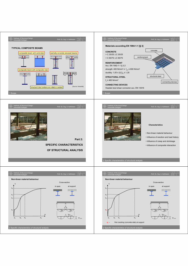
TYPICAL COMPOSITE BEAMS
Seite 4 von Hanswille einfügen
1 Scope
[Source: Hanswille]
Institute of Structural DesignUniversität Stuttgart Prof. Dr.-Ing. U. Kuhlmann
Materials according EN 1994-1-1 [§ 3]
CONCRETE
REINFORCEMENT
STRUCTURAL STEEL
> C 20/25; LC 20/25
< C 60/75; LC 60/75
Acc. EN 1992-1-1 § 3.2
strength: 400 N/mm2 fy,k 600 N/mm2
ductility: 1,05 (ft/fy)k 1,35
fy 460 N/mm2
CONNECTING DEVICESHeaded stud shear connector acc. EN 13918
structural steel
connecting devices
reinforcement
concrete
1 Scope
Institute of Structural DesignUniversität Stuttgart Prof. Dr.-Ing. U. Kuhlmann
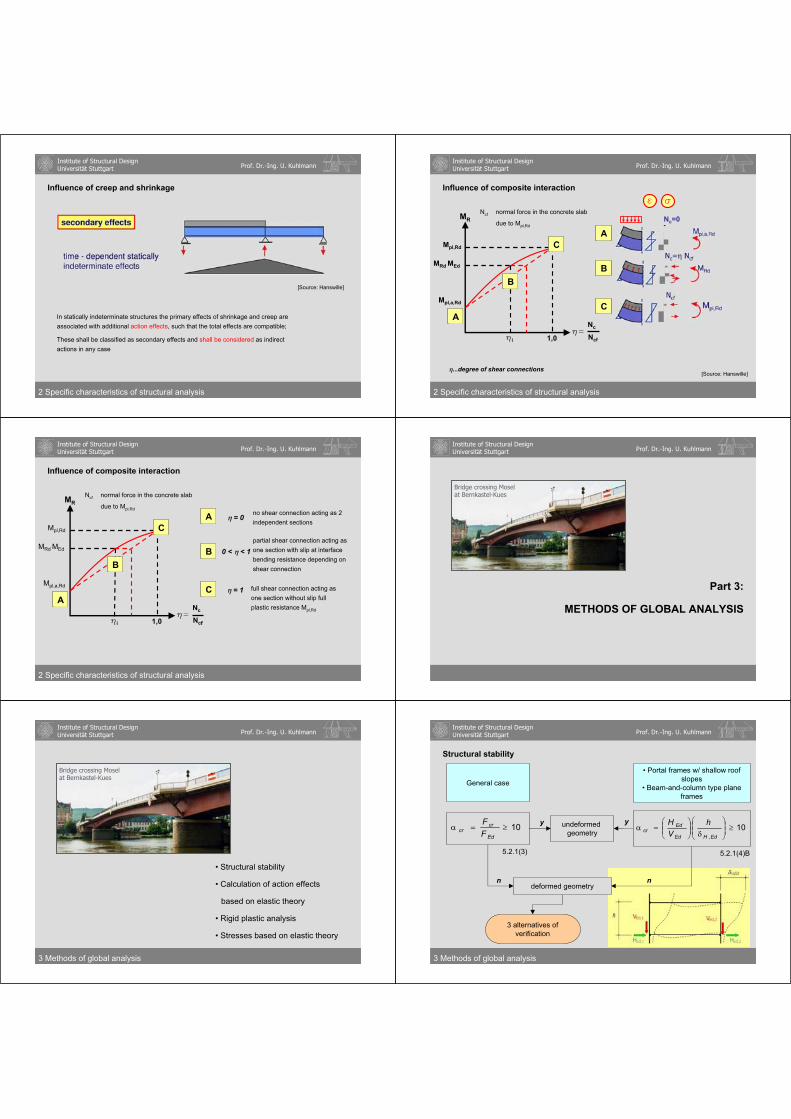
Part 2:
SPECIFIC CHARACTERISTICS
OF STRUCTURAL ANALYSIS
source:[ESDEP]
Institute of Structural DesignUniversität Stuttgart Prof. Dr.-Ing. U. Kuhlmann
2 Specific characteristics of structural analysis
• Non-linear material behaviour
• Influence of erection and load history
• Influence of creep and shrinkage
• Influence of composite interaction
Characteristics
source:[ESDEP]
Institute of Structural DesignUniversität Stuttgart Prof. Dr.-Ing. U. Kuhlmann
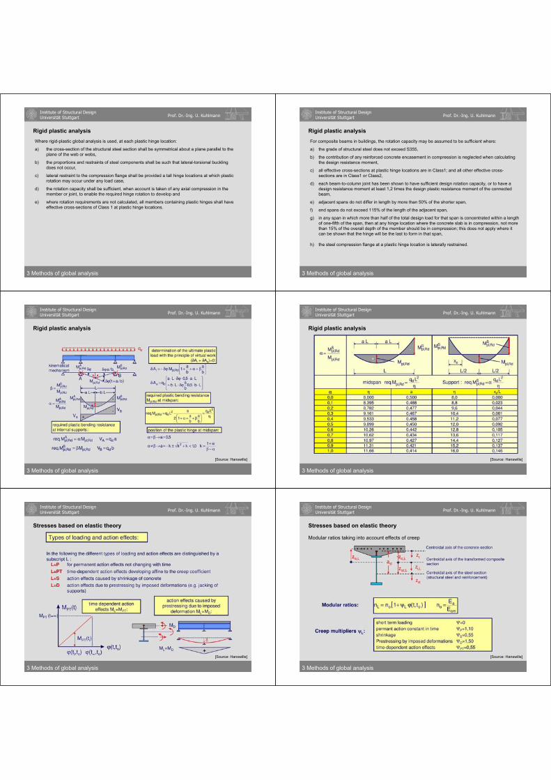
Non-linear material behaviour
q1
w1 w2 w3 w4
q2
q3
q4
q
w
w w
2 Specific characteristics of structural analysis
M-pl,Rd
M+pl,Rd
Cross-section
at supportin span
Institute of Structural DesignUniversität Stuttgart Prof. Dr.-Ing. U. Kuhlmann
Non-linear material behaviour
q1
w1 w2 w3 w4
q2
q3
q4
q
w
w w
2 Specific characteristics of structural analysis
q1 – first cracking (concrete slab) at support
M-pl,Rd
M+pl,Rd
Cross-section
at supportin span

Institute of Structural DesignUniversität Stuttgart Prof. Dr.-Ing. U. Kuhlmann
Non-linear material behaviour
q1
w1 w2 w3 w4
q2
q3
q4
q
w
w w
2 Specific characteristics of structural analysis
q2 – first yielding (steel section) at support
M-pl,Rd
M+pl,Rd
Cross-section
at supportin span
Institute of Structural DesignUniversität Stuttgart Prof. Dr.-Ing. U. Kuhlmann
Non-linear material behaviour
q1
w1 w2 w3 w4
q2
q3
q4
q
w
w w
2 Specific characteristics of structural analysis
q3 – first plastic hinge M-pl.Rd at support
M-pl,Rd
M+pl,Rd
Cross-section
at supportin span
Institute of Structural DesignUniversität Stuttgart Prof. Dr.-Ing. U. Kuhlmann
Non-linear material behaviour
q1
w1 w2 w3 w4
q2
q3
q4
q
w
w w
Cross-section
at supportin span
2 Specific characteristics of structural analysis
q4 – last plastic hinge M+pl.Rd in span
M-pl,Rd
M+pl,Rd
Institute of Structural DesignUniversität Stuttgart Prof. Dr.-Ing. U. Kuhlmann
M+pl,Rd
M+pl,Rd
M-pl,Rd
M-pl,Rd
Cross-section in span
Cross-section at support
2 Specific characteristics of structural analysis
Non-linear material behaviour
+
-cfcd
fyd
fyd
fyd
fsd
++
-
q1
q2
q3
q4
q MM
Institute of Structural DesignUniversität Stuttgart Prof. Dr.-Ing. U. Kuhlmann
High efficiency of plastic hinge theory due to difference of plastic bending moment in span and at support - requires rotation capacity of section with first plastic hinge (at support)
2 Specific characteristics of structural analysis
0,2 0,4 0,6 0,8 1,0
2,0
4,0
6,0
8,0
10,0
12,0
q4 = qpl
q3
q
ql2q =
Mpl,F
Mpl,F
Mpl,Stpl =
load level q3
load level q4= qpl
Mpl,St
Mpl,St
Mpl,F
l l
qNon-linear material behaviour
Institute of Structural DesignUniversität Stuttgart Prof. Dr.-Ing. U. Kuhlmann
2 Specific characteristics of structural analysis
Non-linear material behaviour
[Source: Hanswille]

Institute of Structural DesignUniversität Stuttgart Prof. Dr.-Ing. U. Kuhlmann
[Source: Hanswille]
2 Specific characteristics of structural analysis
Non-linear material behaviour
Institute of Structural DesignUniversität Stuttgart Prof. Dr.-Ing. U. Kuhlmann
[Source: Hanswille]
Classes 1 and 2
2 Specific characteristics of structural analysis
Non-linear material behaviour
Institute of Structural DesignUniversität Stuttgart Prof. Dr.-Ing. U. Kuhlmann
2 Specific characteristics of structural analysis
Non-linear material behaviour
[Source: Hanswille]
Class 3
Institute of Structural DesignUniversität Stuttgart Prof. Dr.-Ing. U. Kuhlmann
[Source: Hanswille]
Classification with partial concrete encasement
2 Specific characteristics of structural analysis
Non-linear material behaviour
Institute of Structural DesignUniversität Stuttgart Prof. Dr.-Ing. U. Kuhlmann
Reinforcement in tension flanges
2 Specific characteristics of structural analysis
Non-linear material behaviour
[Source: Hanswille]
Institute of Structural DesignUniversität Stuttgart Prof. Dr.-Ing. U. Kuhlmann
Influence of erection and load history
Example:Bridge Arminiusstraße in Dortmund
- erection steel structure
3 spansR = 900 m
2 Specific characteristics of structural analysis

Institute of Structural DesignUniversität Stuttgart Prof. Dr.-Ing. U. Kuhlmann
Raising at inner supportsExample:Bridge Arminiusstraße in Dortmund
- raising at inner supports- scaffolding hanging at steel structure- concreting and hardening of concrete- lowering at inner supports- finalizing (pavement etc.)- traffic opening
2 Specific characteristics of structural analysis
Influence of erection and load history
Institute of Structural DesignUniversität Stuttgart Prof. Dr.-Ing. U. Kuhlmann
[Source: Hanswille]
2 Specific characteristics of structural analysis
Influence of erection and load history
Institute of Structural DesignUniversität Stuttgart Prof. Dr.-Ing. U. Kuhlmann
A
B
C
unpropped construction
propped construction
propped construction + jacking of props
2 Specific characteristics of structural analysis
[Source: Hanswille]
Influence of erection and load history
Institute of Structural DesignUniversität Stuttgart Prof. Dr.-Ing. U. Kuhlmann
The bending capacity Mpl,Rd isindependent of the loading history in case of Class 1 or Class 2 cross sections
Using Class 3 or Class 4 cross sections the elastic behaviour of the loading history has to be taken into account in ULS
[Source: Hanswille]
2 Specific characteristics of structural analysis
Influence of erection and load history
Institute of Structural DesignUniversität Stuttgart Prof. Dr.-Ing. U. Kuhlmann
Influence of creep and shrinkage
2 Specific characteristics of structural analysis
The effects of shrinkage and creep of concrete result in internal forces in cross sections, and curvatures and longitudinal strains in members
[Source: Hanswille]
Institute of Structural DesignUniversität Stuttgart Prof. Dr.-Ing. U. Kuhlmann
2 Specific characteristics of structural analysis
creep and shrinkage has to be consideredFor Class 3 and 4 sections
bending capacity independent of creep and shrinkageFor Class 1 and 2 sections
only external deformationsFor statically determinate structures:
Due to creep and shrinkage:
[Source: Hanswille]
Influence of creep and shrinkage
Institute of Structural DesignUniversität Stuttgart Prof. Dr.-Ing. U. Kuhlmann
[Source: Hanswille]
2 Specific characteristics of structural analysis
In statically indeterminate structures the primary effects of shrinkage and creep are associated with additional action effects, such that the total effects are compatible;
These shall be classified as secondary effects and shall be considered as indirect actions in any case
Influence of creep and shrinkage
Institute of Structural DesignUniversität Stuttgart Prof. Dr.-Ing. U. Kuhlmann
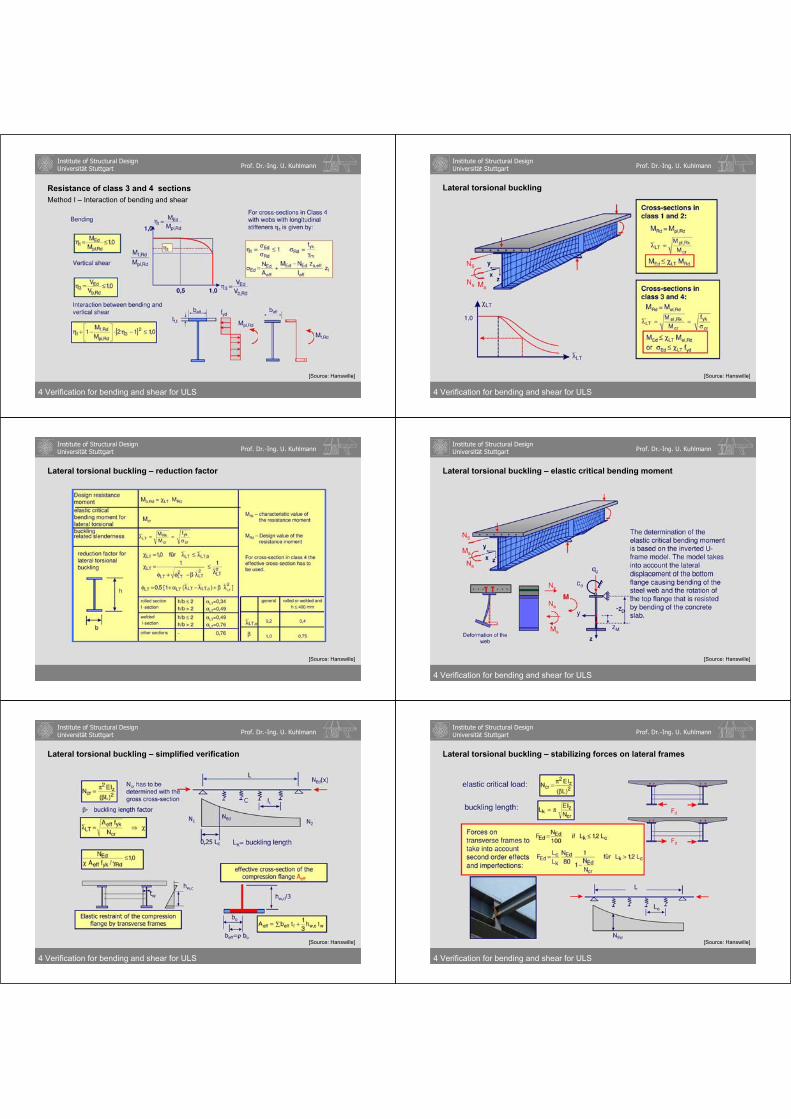
Influence of composite interaction
[Source: Hanswille]
2 Specific characteristics of structural analysis
MRd MEd
MR
Mpl,Rd
Mpl,a,Rd
hi 1,0 Ncf
Nch=
A
B
CA
B
C
Ncf normal force in the concrete slab
due to Mpl,Rd
e
Nc=0
...degree of shear connections
Institute of Structural DesignUniversität Stuttgart Prof. Dr.-Ing. U. Kuhlmann
2 Specific characteristics of structural analysis
MRd MEd
MR
Mpl,Rd
Mpl,a,Rd
hi 1,0 Ncf
Nch=
A
B
CA
B
C
Ncf normal force in the concrete slab
due to Mpl,Rd
e
Nc=0
= 0
0 < < 1
= 1
no shear connection acting as 2 independent sections
full shear connection acting as one section without slip full plastic resistance Mpl,Rd
partial shear connection acting as one section with slip at interfacebending resistance depending on shear connection
Influence of composite interaction
Institute of Structural DesignUniversität Stuttgart Prof. Dr.-Ing. U. Kuhlmann
Part 3:
METHODS OF GLOBAL ANALYSIS
Bridge crossing Mosel at Bernkastel-Kues
Institute of Structural DesignUniversität Stuttgart Prof. Dr.-Ing. U. Kuhlmann
• Structural stability
• Calculation of action effects
based on elastic theory
• Rigid plastic analysis
• Stresses based on elastic theory
3 Methods of global analysis
Bridge crossing Mosel at Bernkastel-Kues
Institute of Structural DesignUniversität Stuttgart Prof. Dr.-Ing. U. Kuhlmann
General case
• Portal frames w/ shallow roofslopes
• Beam-and-column type plane frames
undeformedgeometry
10Ed
crcr F
F
deformed geometry
10Ed,HEd
Edcr
hVH
n
5.2.1(3)
y
n
3 alternatives of verification
5.2.1(4)B
y
Structural stability
3 Methods of global analysis

Institute of Structural DesignUniversität Stuttgart Prof. Dr.-Ing. U. Kuhlmann
3 alternatives of verification
Global second-order analysis + individual stability check of
membersEquivalent column method
EN 1994-1-1 5.2.2 (3)EN 1994-1-1 6.7.3.6 / 7
EN 1994-1-1 5.2.2 (6) b) and 5.2.2 (6) c)
Only for steel columns:EN 1993-1-1 5.2.2 (3) c)
5.2.2 (8)
Second-order analysisof whole system
3 Methods of global analysis
Structural stability
Institute of Structural DesignUniversität Stuttgart Prof. Dr.-Ing. U. Kuhlmann
Second-order analysisof whole system
accounting forglobal and localimperfections
0
w0
w0
3 alternatives of verification
3 Methods of global analysis
Structural stability
Institute of Structural DesignUniversität Stuttgart Prof. Dr.-Ing. U. Kuhlmann
including global imperfections
Individual stability check of members acc. to EN 1994-1-1
6.7.3.4 or 6.7.3.5
Buckling length = system length
Global second-order analysis + individual stability check of
members
3 alternatives of verification
3 Methods of global analysis
Structural stability
Institute of Structural DesignUniversität Stuttgart Prof. Dr.-Ing. U. Kuhlmann
Equivalent column method
neither global nor localimperfections
Equivalent columnmethod for member acc. EN 1993-1-1 6.3.1/2/3
Buckling length by global eigenvalue determination
3 alternatives of verification
3 Methods of global analysis
Structural stability
Institute of Structural DesignUniversität Stuttgart Prof. Dr.-Ing. U. Kuhlmann
Second-order analysisof whole system
accounting forglobal and localimperfections
including global imperfections
Individual stability check of members acc. to EN1994-1-1
6.7.3.4 or 6.7.3.5
Buckling length = member length
Global second-order analysis + individual stability check of
membersEquivalent column method
neither global nor localimperfections
Buckling length by global eigenvalue determination
3 alternatives of verification
Equivalent columnmethod for member acc. EN 1993-1-1 6.3.1/2/3
3 Methods of global analysis
Structural stability
Institute of Structural DesignUniversität Stuttgart Prof. Dr.-Ing. U. Kuhlmann
Calculation of action effects based on elastic theory
3 Methods of global analysis
[Source: Hanswille]

Institute of Structural DesignUniversität Stuttgart Prof. Dr.-Ing. U. Kuhlmann
3 Methods of global analysis
Calculation of action effects based on elastic theory - General method
[Source: Hanswille]
Institute of Structural DesignUniversität Stuttgart Prof. Dr.-Ing. U. Kuhlmann
[Source: Hanswille]
3 Methods of global analysis
Calculation of action effects based on elastic theory
Institute of Structural DesignUniversität Stuttgart Prof. Dr.-Ing. U. Kuhlmann
3 Methods of global analysis
Calculation of action effects based on elastic theory
[Source: Hanswille]
Institute of Structural DesignUniversität Stuttgart Prof. Dr.-Ing. U. Kuhlmann
Relation Classification - method of global analysis - resistance
3 Methods of global analysis
[Source: Hanswille]
Institute of Structural DesignUniversität Stuttgart Prof. Dr.-Ing. U. Kuhlmann
Rigid plastic analysis
[Source: Hanswille]
3 Methods of global analysis
Rigid plastic global analysis may be used for ultimate limit state verifications other than fatigue, where second-order effects do not have to be considered and provided that all the members and joints of the frame are steel or composite, the steel material satisfies ductility requirements EN 1993-1-1, the cross-sections of steel members have sufficientrotation capacity and the joints are able to sustain their plastic resistance moments for a sufficient rotation capacity.
Institute of Structural DesignUniversität Stuttgart Prof. Dr.-Ing. U. Kuhlmann
3 Methods of global analysis
pl,Rd
+
-zpl
h
L
Fd
qd
> 0,5zpl
h0,15 if
Fd
Fd + qd L
Le Li
Lmax Lmin
Limitation of span ratio:
exterior span: Le < 1,15 Li
interior span: Lmax/Lmin 1,50
Beam with single load and rotation requirements at span:
Rigid plastic analysis
Institute of Structural DesignUniversität Stuttgart Prof. Dr.-Ing. U. Kuhlmann
Where rigid-plastic global analysis is used, at each plastic hinge location:
a) the cross-section of the structural steel section shall be symmetrical about a plane parallel to the plane of the web or webs,
b) the proportions and restraints of steel components shall be such that lateral-torsional buckling does not occur,
c) lateral restraint to the compression flange shall be provided a tall hinge locations at which plastic rotation may occur under any load case,
d) the rotation capacity shall be sufficient, when account is taken of any axial compression in the member or joint, to enable the required hinge rotation to develop and
e) where rotation requirements are not calculated, all members containing plastic hinges shall have effective cross-sections of Class 1 at plastic hinge locations.
3 Methods of global analysis
Rigid plastic analysis
Institute of Structural DesignUniversität Stuttgart Prof. Dr.-Ing. U. Kuhlmann
For composite beams in buildings, the rotation capacity may be assumed to be sufficient where:
a) the grade of structural steel does not exceed S355,
b) the contribution of any reinforced concrete encasement in compression is neglected when calculating the design resistance moment,
c) all effective cross-sections at plastic hinge locations are in Class1; and all other effective cross-sections are in Class1 or Class2,
d) each beam-to-column joint has been shown to have sufficient design rotation capacity, or to have a design resistance moment at least 1,2 times the design plastic resistance moment of the connected beam,
e) adjacent spans do not differ in length by more than 50% of the shorter span,
f) end spans do not exceed 115% of the length of the adjacent span,
g) in any span in which more than half of the total design load for that span is concentrated within a length of one-fifth of the span, then at any hinge location where the concrete slab is in compression, not more than 15% of the overall depth of the member should be in compression; this does not apply where it can be shown that the hinge will be the last to form in that span,
h) the steel compression flange at a plastic hinge location is laterally restrained.
3 Methods of global analysis
Rigid plastic analysis
Institute of Structural DesignUniversität Stuttgart Prof. Dr.-Ing. U. Kuhlmann
3 Methods of global analysis
[Source: Hanswille]
Rigid plastic analysis
Institute of Structural DesignUniversität Stuttgart Prof. Dr.-Ing. U. Kuhlmann
3 Methods of global analysis
Rigid plastic analysis
[Source: Hanswille]
Institute of Structural DesignUniversität Stuttgart Prof. Dr.-Ing. U. Kuhlmann
Stresses based on elastic theory
3 Methods of global analysis
[Source: Hanswille]
Institute of Structural DesignUniversität Stuttgart Prof. Dr.-Ing. U. Kuhlmann
Stresses based on elastic theory
Modular ratios taking into account effects of creep
3 Methods of global analysis
[Source: Hanswille]

Institute of Structural DesignUniversität Stuttgart Prof. Dr.-Ing. U. Kuhlmann
Stresses based on elastic theory
Elastic cross section properties taking into account creep
3 Methods of global analysis
[Source: Hanswille]
Institute of Structural DesignUniversität Stuttgart Prof. Dr.-Ing. U. Kuhlmann
3 Methods of global analysis
Stresses based on elastic theory
[Source: Hanswille]
Institute of Structural DesignUniversität Stuttgart Prof. Dr.-Ing. U. Kuhlmann
Stresses based on elastic theory
Primary effects due to shrinkage
3 Methods of global analysis
[Source: Hanswille]
Institute of Structural DesignUniversität Stuttgart Prof. Dr.-Ing. U. Kuhlmann
Stresses based on elastic theory
Primary effects due to shrinkage
3 Methods of global analysis
[Source: Hanswille]
Institute of Structural DesignUniversität Stuttgart Prof. Dr.-Ing. U. Kuhlmann
Part 4:
VERIFICATION FOR BENDING AND SHEAR
FOR ULTIMATE LIMITE STATE
Institute of Structural DesignUniversität Stuttgart Prof. Dr.-Ing. U. Kuhlmann
4 Verification for bending and shear for ULS
• General
• Resistance of class 1 and 2 sections
• Resistance of class 3 and 4 sections
• Lateral torsional buckling

Institute of Structural DesignUniversität Stuttgart Prof. Dr.-Ing. U. Kuhlmann
General - Basis of design
4 Verification for bending and shear for ULS
Rd=Mpl,Rd
Ed Rd
Ultimate limitstate:
Ed Cd
Serviceabilitliylimit state:
[Source: Hanswille]
Institute of Structural DesignUniversität Stuttgart Prof. Dr.-Ing. U. Kuhlmann
4 Verification for bending and shear for ULS
Partial safety factor for concrete C according to EN 1992-1-1 e.g. C = 1.5
Partial safety factor for reinforcement steelS according to EN 1992-1-1 e.g. S= 1.15
Partial safety factor for structural steela according to EN 1993-1-1 e.g. M0 = 1.0
General - Basis of design
[Source: Hanswille]
Institute of Structural DesignUniversität Stuttgart Prof. Dr.-Ing. U. Kuhlmann
4 Verification for bending and shear for ULS
General - Basis of design
Institute of Structural DesignUniversität Stuttgart Prof. Dr.-Ing. U. Kuhlmann
4 Verification for bending and shear for ULS
General - Required verifications for composite beams
[Source: Hanswille]
Institute of Structural DesignUniversität Stuttgart Prof. Dr.-Ing. U. Kuhlmann
4 Verification for bending and shear for ULS
General - Required verifications for composite beams
[Source: Hanswille]
Institute of Structural DesignUniversität Stuttgart Prof. Dr.-Ing. U. Kuhlmann
4 Verification for bending and shear for ULS
General – Critical cross section
[Source: Hanswille]

Institute of Structural DesignUniversität Stuttgart Prof. Dr.-Ing. U. Kuhlmann
4 Verification for bending and shear for ULS
General – Effective width
[Source: Hanswille]
Institute of Structural DesignUniversität Stuttgart Prof. Dr.-Ing. U. Kuhlmann
4 Verification for bending and shear for ULS
General – Effective width of concrete flanges
[Source: Hanswille]
Institute of Structural DesignUniversität Stuttgart Prof. Dr.-Ing. U. Kuhlmann
4 Verification for bending and shear for ULS
General – Non-linear bending resistance
[Source: Hanswille]
Institute of Structural DesignUniversität Stuttgart Prof. Dr.-Ing. U. Kuhlmann
4 Verification for bending and shear for ULS
Classification girders
[Source: Hanswille]
Institute of Structural DesignUniversität Stuttgart Prof. Dr.-Ing. U. Kuhlmann
Resistance of class 1 and 2 sections - classification
4 Verification for bending and shear for ULS
[Source: Hanswille]
Institute of Structural DesignUniversität Stuttgart Prof. Dr.-Ing. U. Kuhlmann
Reduction of plastic bending resistance
4 Verification for bending and shear for ULS
[Source: Hanswille]

Institute of Structural DesignUniversität Stuttgart Prof. Dr.-Ing. U. Kuhlmann
4 Verification for bending and shear for ULS
Reduction of plastic bending resistance
[Source: Hanswille]
Institute of Structural DesignUniversität Stuttgart Prof. Dr.-Ing. U. Kuhlmann
4 Verification for bending and shear for ULS
Resistance of class 1 and 2 sections
[Source: Hanswille]
0,5 1,0
Institute of Structural DesignUniversität Stuttgart Prof. Dr.-Ing. U. Kuhlmann
Resistance of class 1 and 2 sections - Full and partial shear connection
4 Verification for bending and shear for ULS
[Source: Hanswille]
Institute of Structural DesignUniversität Stuttgart Prof. Dr.-Ing. U. Kuhlmann
Resistance of class 1 and 2 sections - Partial shear connection - general
4 Verification for bending and shear for ULS
[Source: Hanswille]
design resistance of studs
Institute of Structural DesignUniversität Stuttgart Prof. Dr.-Ing. U. Kuhlmann
Resistance of class 1 and 2 sections Partial shear connection – determination of moment resistance
4 Verification for bending and shear for ULS
[Source: Hanswille]
Institute of Structural DesignUniversität Stuttgart Prof. Dr.-Ing. U. Kuhlmann
4 Verification for bending and shear for ULS
Resistance of class 1 and 2 sections Partial shear connection – determination of moment resistance
[Source: Hanswille]

Institute of Structural DesignUniversität Stuttgart Prof. Dr.-Ing. U. Kuhlmann
Resistance of class 3 and 4 sections - class 3
4 Verification for bending and shear for ULS
[Source: Hanswille]
Institute of Structural DesignUniversität Stuttgart Prof. Dr.-Ing. U. Kuhlmann
4 Verification for bending and shear for ULS
Resistance of class 3 and 4 sections - class 4
[Source: Hanswille]
Institute of Structural DesignUniversität Stuttgart Prof. Dr.-Ing. U. Kuhlmann
Resistance of class 3 and 4 sections Class 4 – Determination of stresses
4 Verification for bending and shear for ULS
[Source: Hanswille]
Institute of Structural DesignUniversität Stuttgart Prof. Dr.-Ing. U. Kuhlmann
Resistance of class 3 and 4 sections Cross section: class 4 – bending resistance (method I)
4 Verification for bending and shear for ULS
[Source: Hanswille]
Institute of Structural DesignUniversität Stuttgart Prof. Dr.-Ing. U. Kuhlmann
Resistance of class 3 and 4 sections Resistance to vertical shear
4 Verification for bending and shear for ULS
[Source: Hanswille]
Institute of Structural DesignUniversität Stuttgart Prof. Dr.-Ing. U. Kuhlmann
4 Verification for bending and shear for ULS
Resistance of class 3 and 4 sections Resistance to vertical shear
[Source: Hanswille]
Institute of Structural DesignUniversität Stuttgart Prof. Dr.-Ing. U. Kuhlmann
Resistance of class 3 and 4 sections Method I – Interaction of bending and shear
4 Verification for bending and shear for ULS
[Source: Hanswille]
Institute of Structural DesignUniversität Stuttgart Prof. Dr.-Ing. U. Kuhlmann
Lateral torsional buckling
4 Verification for bending and shear for ULS
[Source: Hanswille]
Institute of Structural DesignUniversität Stuttgart Prof. Dr.-Ing. U. Kuhlmann
Lateral torsional buckling – reduction factor
[Source: Hanswille]
Institute of Structural DesignUniversität Stuttgart Prof. Dr.-Ing. U. Kuhlmann
Lateral torsional buckling – elastic critical bending moment
4 Verification for bending and shear for ULS
[Source: Hanswille]
Institute of Structural DesignUniversität Stuttgart Prof. Dr.-Ing. U. Kuhlmann
Lateral torsional buckling – simplified verification
[Source: Hanswille]
4 Verification for bending and shear for ULS
Institute of Structural DesignUniversität Stuttgart Prof. Dr.-Ing. U. Kuhlmann
Lateral torsional buckling – stabilizing forces on lateral frames
4 Verification for bending and shear for ULS
[Source: Hanswille]

Institute of Structural DesignUniversität Stuttgart Prof. Dr.-Ing. U. Kuhlmann
Lateral torsional buckling – without direct calculation
4 Verification for bending and shear for ULS
[Source: Hanswille]
Institute of Structural DesignUniversität Stuttgart Prof. Dr.-Ing. U. Kuhlmann
Part 5:
SHEAR CONNECTION
Institute of Structural DesignUniversität Stuttgart Prof. Dr.-Ing. U. Kuhlmann
• Longitudinal shear forces• Determination of longitudinal shear forces• Full and partial shear connection• Requirements for shear connectors
• Headed studs• Head studs as shear connector• Horizontally lying studs• Headed studs used with profiled steel sheeting
• Longitudinal shear forces in concrete slab Part 5:
SHEAR CONNECTION
5 Shear connection
Institute of Structural DesignUniversität Stuttgart Prof. Dr.-Ing. U. Kuhlmann
Part 5:
SHEAR CONNECTION
• Longitudinal shear forces• Determination of longitudinal shear forces• Full and partial shear connection• Requirements for shear connectors
• Headed studs• Head studs as shear connector• Horizontally lying studs• Headed studs used with profiled steel sheeting
• Longitudinal shear forces in concrete slab
5 Shear connection
Institute of Structural DesignUniversität Stuttgart Prof. Dr.-Ing. U. Kuhlmann
Longitudinal shear forces
5 Shear connection
[Source: Hanswille]
Institute of Structural DesignUniversität Stuttgart Prof. Dr.-Ing. U. Kuhlmann
Determination of longitudinal shear forces - general
5 Shear connection
[Source: Hanswille]

Institute of Structural DesignUniversität Stuttgart Prof. Dr.-Ing. U. Kuhlmann
Determination of longitudinal shear forces - by simplified method for Nc
5 Shear connection
[Source: Hanswille]
Institute of Structural DesignUniversität Stuttgart Prof. Dr.-Ing. U. Kuhlmann
Partial shear connection – determination of longitudinal shear forces
5 Shear connection
[Source: Hanswille]
Institute of Structural DesignUniversität Stuttgart Prof. Dr.-Ing. U. Kuhlmann
M
Requirements for shear connection – uniformly distribution
qd
5 Shear connection
[Source: Hanswille]
Institute of Structural DesignUniversität Stuttgart Prof. Dr.-Ing. U. Kuhlmann
Requirements for shear connection – minimum degree
5 Shear connection
[Source: Hanswille]
Institute of Structural DesignUniversität Stuttgart Prof. Dr.-Ing. U. Kuhlmann
Requirements for shear connection – ductility
5 Shear connection
[Source: Hanswille]
Institute of Structural DesignUniversität Stuttgart Prof. Dr.-Ing. U. Kuhlmann
Part 5:
SHEAR CONNECTION
• Longitudinal shear forces• Determination of longitudinal shear forces• Full and partial shear connection• Requirements for shear connectors
• Headed studs• Head studs as shear connector• Horizontally lying studs• Headed studs used with profiled steel sheeting
• Longitudinal shear forces in concrete slab
5 Shear connection
Institute of Structural DesignUniversität Stuttgart Prof. Dr.-Ing. U. Kuhlmann
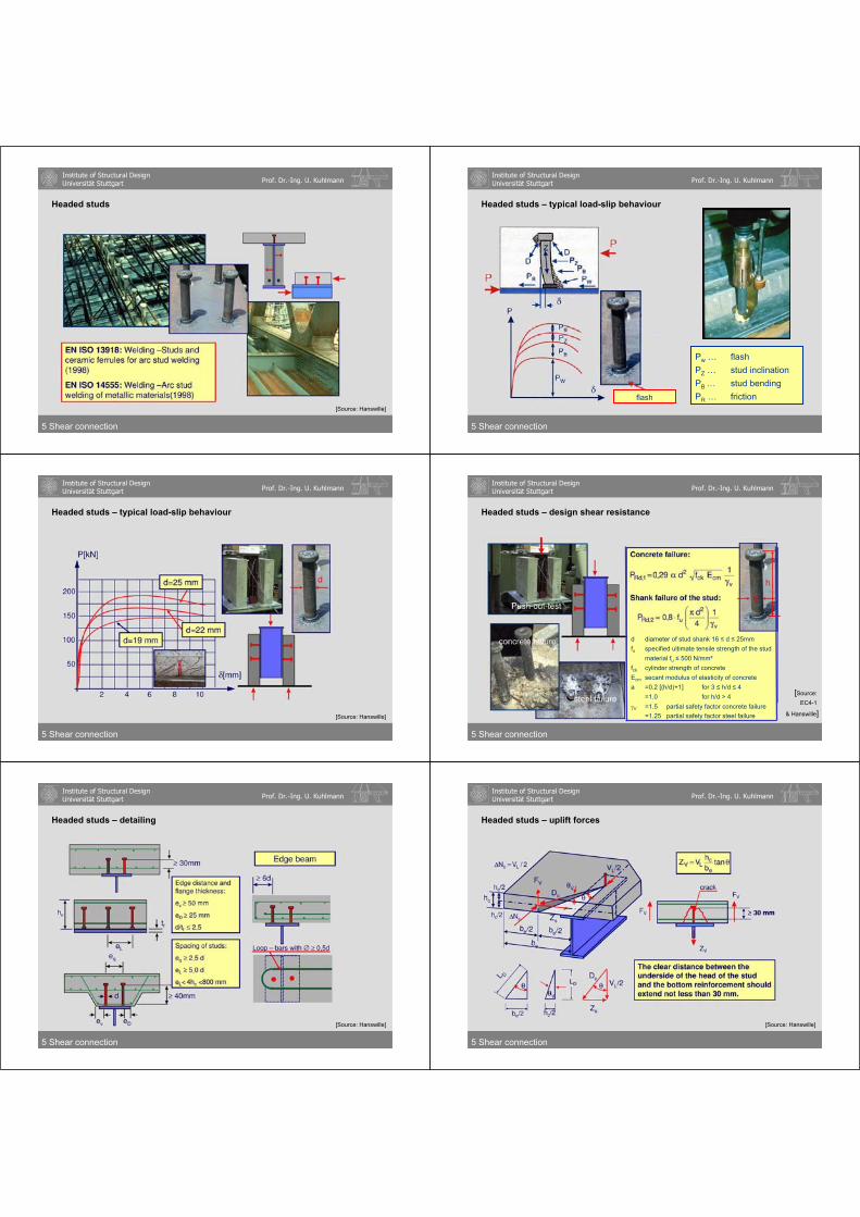
Headed studs
5 Shear connection
[Source: Hanswille]
Institute of Structural DesignUniversität Stuttgart Prof. Dr.-Ing. U. Kuhlmann
Headed studs – typical load-slip behaviour
Pw … flashPZ … stud inclinationPB … stud bendingPR … frictionflash
5 Shear connection
Institute of Structural DesignUniversität Stuttgart Prof. Dr.-Ing. U. Kuhlmann
Headed studs – typical load-slip behaviour
5 Shear connection
[Source: Hanswille]
Institute of Structural DesignUniversität Stuttgart Prof. Dr.-Ing. U. Kuhlmann
Headed studs – design shear resistance
[Source:EC4-1
& Hanswille]
d diameter of stud shank 16 d 25mmfu specified ultimate tensile strength of the stud
material fu 500 N/mm²fck cylinder strength of concreteEcm secant modulus of elasticity of concretea =0.2 [(h/d)+1] for 3 h/d 4
=1.0 for h/d > 4
V =1.5 partial safety factor concrete failure=1.25 partial safety factor steel failure
5 Shear connection
Institute of Structural DesignUniversität Stuttgart Prof. Dr.-Ing. U. Kuhlmann
Headed studs – detailing
5 Shear connection
[Source: Hanswille]
Institute of Structural DesignUniversität Stuttgart Prof. Dr.-Ing. U. Kuhlmann
Headed studs – uplift forces
5 Shear connection
[Source: Hanswille]

Institute of Structural DesignUniversität Stuttgart Prof. Dr.-Ing. U. Kuhlmann
Horizontally lying studs – examples
cast-in-place concrete
prefabricatedconcrete slab
5 Shear connection
Institute of Structural DesignUniversität Stuttgart Prof. Dr.-Ing. U. Kuhlmann
Horizontally lying studs – examples
5 Shear connection
[Source: Hanswille]
Institute of Structural DesignUniversität Stuttgart Prof. Dr.-Ing. U. Kuhlmann
Longitudinal sheardue to beam bending
Vertical sheardue to vertical beam support
Edge position Middle position
Horizontally lying studs – failure modes and position
Concrete edgefailure
Splittingfailure
Vertical shear
Longitudinalshear
5 Shear connection
Institute of Structural DesignUniversität Stuttgart Prof. Dr.-Ing. U. Kuhlmann
[Source: EN1994-2]
Horizontally lying studs – load resistance for longitudinal shear
middle position edge positionsection A-A
v
..'rckv
L,Rds/aadfk.P
304041
a‘r effective edge distancea‘r = ar – cv - s/2 50 mm
kv factor for position of shear connectionkv = 1 edge positionkv = 1.4 middle position
v partial factor 1.25
d … diameter of the stud shank 19 d 25 mmh … overall height of the stud h/d 4s … spacing of stirrups a/2 s a
s/a‘r 3
s… diameter of stirrups s 8 mm
l… diameter of longitudinal reinforment l 10 mm
L,Rdd P.T 30stirrups
5 Shear connection
Institute of Structural DesignUniversität Stuttgart Prof. Dr.-Ing. U. Kuhlmann
[Source: EN1994-2]
Horizontally lying studs – load resistance for vertical shear
middle position edge positionsection A-A
v
v.'
o,r...
ckV,Rd
kas/adf.P
703040500120 a … spacing of studs110 a 440 mm
h … overall height of the studh 100 mm
s… diameter of stirrups
s 12 mm
l… diameter of longitudinal reinforment
l 16 mm
l s
12121 .
V,Rd
V,d.
L,Rd
L,d
PF
PF
Interaction:
5 Shear connection
Institute of Structural DesignUniversität Stuttgart Prof. Dr.-Ing. U. Kuhlmann
Headed studs used with profiled steel sheeting
5 Shear connection
[Source: Hanswille]

Institute of Structural DesignUniversität Stuttgart Prof. Dr.-Ing. U. Kuhlmann
Headed studs used with profiled steel sheeting – load-slip behaviour
5 Shear connection
[Source: Hanswille]
Institute of Structural DesignUniversität Stuttgart Prof. Dr.-Ing. U. Kuhlmann
Headed studs used with profiled steel sheeting – load resistance
5 Shear connection
[Source: Hanswille]
Institute of Structural DesignUniversität Stuttgart Prof. Dr.-Ing. U. Kuhlmann
Headed studs used with profiled steel sheeting – load resistance
5 Shear connection
[Source: Hanswille]
Institute of Structural DesignUniversität Stuttgart Prof. Dr.-Ing. U. Kuhlmann
Part 5:
SHEAR CONNECTION
• Longitudinal shear forces• Determination of longitudinal shear forces• Full and partial shear connection• Requirements for shear connectors
• Headed studs• Head studs as shear connector• Horizontally lying studs• Headed studs used with profiled steel sheeting
• Longitudinal shear forces in concrete slab
5 Shear connection
Institute of Structural DesignUniversität Stuttgart Prof. Dr.-Ing. U. Kuhlmann
Longitudinal shear forces in concrete slab - determination
Slab in compression
Slab in tension
5 Shear connection
[Source: Hanswille]
Institute of Structural DesignUniversität Stuttgart Prof. Dr.-Ing. U. Kuhlmann
Longitudinal shear forces in concrete slab – strut-and-tie model
5 Shear connection
[Source: Hanswille]
Institute of Structural DesignUniversität Stuttgart Prof. Dr.-Ing. U. Kuhlmann
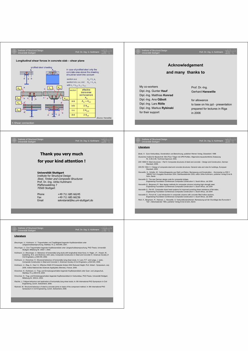
Longitudinal shear forces in concrete slab – shear plane
section a-a: Acv= hc av
section b-b, c-c, d-d: Acv = Lv av
with Lv = Lb-b, Lc-c, Ld-d
section
5 Shear connection
[Source: Hanswille]
Institute of Structural DesignUniversität Stuttgart Prof. Dr.-Ing. U. Kuhlmann
Acknowledgement
and many thanks to
My co-workersDipl.-Ing. Gunter HaufDipl.-Ing. Matthias KonradDipl.-Ing. Ana OžboltDipl.-Ing. Lars RölleDipl.-Ing. Markus Rybinskifor their support
Prof. Dr.-Ing. Gerhard Hanswille
for allowanceto base on his ppt - presentationprepared for lectures in Riga in 2006
Institute of Structural DesignUniversität Stuttgart Prof. Dr.-Ing. U. Kuhlmann
Thank you very much
for your kind attention !
Universität StuttgartInstitute for Structural DesignSteel, Timber and Composite StructuresProf. Dr.-Ing. Ulrike KuhlmannPfaffenwaldring 770569 Stuttgart
Phone +49 711 685 66245Fax +49 711 685 66236Email [email protected]
Institute of Structural DesignUniversität Stuttgart Prof. Dr.-Ing. U. Kuhlmann
Literature
Bode, H.: Euro-Verbundbau, Konstruktion und Berechnung, publisher Werner Verlag, Düsseldorf, 1998
Deutsches Institut für Bautechnik: Slim-Floor Träger mit UPE-Profilen, Allgemeine bauaufsichtliche ZulassungNr. Z-26.2-48, Technical Approval, 2005.
DIN 18800-5: Steel structures – Part 5: Composite structures of steel and concrete – Design and Construction, German Standard, 2006.
DIN EN 1994-1-1: Design of composite steel and concrete structures: General rules and rules for buildings, European Standard, 2002
Hanswille, G., Schäfer, M., Verbundtragwerke aus Stahl und Beton, Bemessung und Konstruktion - Kommentar zu DIN V 188000 Teil 5 Ausgabe November 2004, Stahlbaukalender 2005, editor Ulrike Kuhlmann, publisher Verlag Ernst & Sohn, Berlin
Hanswille G.: The new German design code for composite bridges,Engineering Foundation Conferences Composite Construction V, South Africa, Juli 2004
Hanswille G., Bergmann R.: New design methods for composite columns including high strength steel,Engineering Foundation Conferences Composite Construction V, South Africa, Juli 2004
Hanswille G., Piel W.: Composite shear head systems for improved punshing shear resistance of flat slabs,Engineering Foundation Conferences Composite Construction V, South Africa, Juli 2004
Hanswille G., Porsch M.: Load introduction in composite columns with concrete filled hollow sections,Engineering Foundation Conferences Composite Construction V, South Africa, Juli 2004
Roik, K., Bergmann, R., Haensel, J., Hanswille, G. Verbundkonstruktionen: Bemessung auf der Grundlage des Eurocode 4 Teil 1, Betonkalender 1993, publisher Verlag Ernst & Sohn, Berlin
Institute of Structural DesignUniversität Stuttgart Prof. Dr.-Ing. U. Kuhlmann
Literature
Breuninger, U.; Kuhlmann, U.: Tragverhalten und Tragfähigkeit liegender Kopfbolzendübel unterLängsschubbeanspruchung, Stahlbau 70, p. 835-845, 2001.
Breuninger, U.: Zum Tragverhalten liegender Kopfbolzendübel unter Längsschubbeanspruchung, PhD-Thesis, Universität Stuttgart, Mitteilung Nr. 2000-1, 2000.
Kuhlmann, U.; Breuninger, U.: Behaviour of horizontally lying studs with longitudinal shear force, In: Hajjar, J.F., Hosain, M., Easterling, W.S. and Shahrooz, B.M. (eds), Composite Construction in Steel and Concrete IV, American Society of Civil Engineers, p.438-449, 2002.
Kuhlmann, U.; Kürschner, K.: Structural behaviour of horizontally lying shear studs, In: Leon, R.T. and Lange, J. (eds), Composite Construction in Steel and Concrete V, American Society of Civil Engineers, p.534-543, 2006.
Kuhlmann, U.; Rieg, A.; Hauf, G.; Effective Width Of Composite Girders With Reduced Height, Prof. Aribert - Symposium, July2006, Institut National des Sciences Appliquées (Rennes), France, 2006.
Kürschner, K.; Kuhlmann, U.: Trag- und Ermüdungsverhalten liegender Kopfbolzendübel unter Quer- und Längsschub, Stahlbau 73, p.505-516, 2004.
Kürschner, K.: Trag- und Ermüdungsverhalten liegender Kopfbolzendübel im Verbundbau, PhD-Thesis, Universität Stuttgart, Mitteilung Nr. 2003-4, 2003.
Raichle, J.: Fatigue behaviour and application of horizontally lying shear studs, In: 6th International PhD Symposium in Civil Engineering, Zurich, Switzerland, 2006.
Rybinski, M.: Structural behaviour of steel to concrete joints on basis of the component method, In: 6th International PhD Symposium in Civil Engineering, Zurich, Switzerland, 2006.


SERVICEABILITY LIMIT STATE
G. Hanswille Bergische Universität Wuppertal


1
1
G. HanswilleUniv.-Prof. Dr.-Ing.
Institute for Steel and Composite Structures
University of Wuppertal-Germany
Serviceability limit states of composite beams
Institute for Steel and Composite StructuresUniversity of Wuppertal
Germany
Univ. - Prof. Dr.-Ing. Gerhard Hanswille
Eurocode 4
EurocodesBackground and Applications
Dissemination of information for training18-20 February 2008, Brussels
2
G. HanswilleUniv.-Prof. Dr.-Ing.
Institute for Steel and Composite Structures
University of Wuppertal-Germany
Contents
Part 1: Introduction
Part 2: Global analysis for serviceability limit states
Part 3: Crack width control
Part 4: Deformations
Part 5: Limitation of stresses
Part 6: Vibrations
3
G. HanswilleUniv.-Prof. Dr.-Ing.
Institute for Steel and Composite Structures
University of Wuppertal-Germany
Serviceability limit states
Serviceability limit states
Limitation of stresses
Limitation of deflections
crack width control
vibrations
web breathing4
G. HanswilleUniv.-Prof. Dr.-Ing.
Institute for Steel and Composite Structures
University of Wuppertal-Germany
Serviceability limit states
{ }∑ ∑ ψ+++= i,ki,01,kkj,kd QQPGEEcharacteristic combination:
frequent combination: { }∑ ∑ ψ+ψ++= i,ki,21,k1,1kj,kd QQPGEE
quasi-permanent combination: { }∑ ∑ ψ++= i,ki,2kj,kd QPGEE
serviceability limit states Ed ≤ Cd:
- deformation- crack width - excessive compressive stresses in concrete
Cd= - excessive slip in the interface between steel and concrete
- excessive creep deformation- web breathing- vibrations
5
G. HanswilleUniv.-Prof. Dr.-Ing.
Institute for Steel and Composite Structures
University of Wuppertal-Germany
Part 2:
Global analysis for serviceability limit states
6
G. HanswilleUniv.-Prof. Dr.-Ing.
Institute for Steel and Composite Structures
University of Wuppertal-Germany
Global analysis - General
Calculation of internal forces, deformations and stresses at serviceability limit state shall take into account the followingeffects:
shear lag;
creep and shrinkage of concrete;
cracking of concrete and tension stiffening of concrete;
sequence of construction;
increased flexibility resulting from significant incompleteinteraction due to slip of shear connection;
inelastic behaviour of steel and reinforcement, if any;
torsional and distorsional warping, if any.

2
7
G. HanswilleUniv.-Prof. Dr.-Ing.
Institute for Steel and Composite Structures
University of Wuppertal-Germany
Shear lag- effective width
σmax
σmax
b
be
The flexibility of steel or concrete flanges affected by shear in their plane (shear lag) shall be used either by rigorous analysis, or by using an effective width be
2,0bb
i
ei ≥
σmax
bei
bi
5 bei
y
bi
y
σmax
bei
σ(y)
σ(y)
2,0bb
i
ei <
σR
[ ]4
iRmaxR
maxi
eiR
by1)y(
2,0bb25,1
⎥⎦
⎤⎢⎣
⎡−σ−σ+σ=σ
σ⎥⎦
⎤⎢⎣
⎡−=σ
4
imax b
y1)y( ⎥⎦
⎤⎢⎣
⎡−σ=σ
shear lag
real stress distribution
stresses taking into account the effective width
8
G. HanswilleUniv.-Prof. Dr.-Ing.
Institute for Steel and Composite Structures
University of Wuppertal-Germany
midspan regions and internal supports:
beff = b0 + be,1+be,2
be,i= Le/8
Le – equivalent lengthend supports: beff = b0 + β1 be,1+β2 be,2
βi = (0,55+0,025 Le/bi) ≤ 1,0
Effective width of concrete flanges
Le=0,85 L1 for beff,1 Le=0,70 L2 for beff,1
Le=0,25 (L1 + L2) for beff,2 Le=2L3 for beff,2
L1 L2L3
beff,0
beff,1beff,1beff,2
beff,2
L1/4 L1/2 L1/4 L2/2L2/4 L2/4
bobe,1 be,2
bob1 b2
9
G. HanswilleUniv.-Prof. Dr.-Ing.
Institute for Steel and Composite Structures
University of Wuppertal-Germany
Initial sectional forces
redistribution of the sectional forces due to creep
ML
-Nc,o
Mc,o
Mst,o
Nst,o
Nc,r
-Mc,r
Mst,r
-Nst,r
zi,st
-zi,c ast
Effects of creep of concrete
primary effects
The effects of shrinkage and creep of concrete and non-uniform changes of temperature result in internal forces in cross sections, and curvatures and longitudinal strains in members; the effects that occur in statically determinate structures, and in statically indeterminate structures when compatibility of the deformations is not considered, shall be classified as primary effects.
10
G. HanswilleUniv.-Prof. Dr.-Ing.
Institute for Steel and Composite Structures
University of Wuppertal-Germany
Effects of creep and shrinkage of concrete
Types of loading and action effects:
In the following the different types of loading and action effects are distinguished by a subscript L :
L=P for permanent action effects not changing with timeL=PT time-dependent action effects developing affine to the creep coefficientL=S action effects caused by shrinkage of concreteL=D action effects due to prestressing by imposed deformations (e.g. jacking of
supports)
MPT(t)MPT (t=∞)
ϕ(t,to)ϕ(t∞,to)ϕ(ti,to)
time dependent action effects ML=MPT:
action effects caused by prestressing due to imposed
deformation ML=MD:
δ
ML=MD +
MD
MPT(ti)
11
G. HanswilleUniv.-Prof. Dr.-Ing.
Institute for Steel and Composite Structures
University of Wuppertal-Germany
Modular ratios taking into account effects of creep
[ ]cm
aooLoL E
En)t,t(1nn =ϕψ+=Modular ratios:
centroidal axis of the concrete section
centroidal axis of the transformed composite section
centroidal axis of the steel section (structural steel and reinforcement)
-zic,L
zist,Lzi,L
zczis,Last
zst
ΨPT=0,55time-dependent action effectsΨD=1,50prestressing by controlled imposed deformationsΨS=0,55shrinkageΨP=1,10permanent action not changing in time
Ψ=0short term loadingcreep multiplieraction
12
G. HanswilleUniv.-Prof. Dr.-Ing.
Institute for Steel and Composite Structures
University of Wuppertal-Germany
)t(EEn
ocm
sto =
Modular ratio taking into account creep effect:centroidal axis of the
concrete section
L,i2stL,cstL,cstL,i A/aAAJJJ ++=L,cStL,i AAA +=
L,iststL,ic A/aAz −=LcL,cLcL,c n/JJn/AA ==
-zic,L
zist,Lzi,L
zc-zis,L
ast
zst
Transformed cross-section properties of the concrete section:
Transformed cross-section area of the composite section:
Second moment of area of the composite section:
Distance between the centroidal axes of the concrete and the composite section:
))t,t(1(nn 0L0L ϕψ+=
Elastic cross-section properties of the composite section taking into account creep effects
centroidal axis of the composite section
centroidal axis of the steel section

3
13
G. HanswilleUniv.-Prof. Dr.-Ing.
Institute for Steel and Composite Structures
University of Wuppertal-Germany
Effects of cracking of concrete and tension stiffening of concrete between cracks
ε
εs(x)
εc(x)
Ns Ns
c
ctEf
s
2s2,s E
σ=ε
r,sεΔβ
εsr,1 εsr,2 εsm,y εsy
Ns
Nsy
Nsm
Ns,cr
B C
σs,2σs(x)
σc(x)
τv
xstage A: uncracked sectionstage B: initial crack formationstage C: stabilised crack formation
σc(x)
fully cracked section
A
σc(x)
σs(x)
mean strain εsm=εs,2- βΔεs,r
r,sεΔ
εsm
r,ss εΔβ=εΔ
ss
eff,cts E
fρ
β=εΔ
css A/A=ρ
4,0=β
14
G. HanswilleUniv.-Prof. Dr.-Ing.
Institute for Steel and Composite Structures
University of Wuppertal-Germany
-κ
εsm
MMs≈0
Ma
Na
εa
a
zs
Ns equilibrium:
aNMM sa −=
sa NN −=
εs,m
εs,2Δεs=β Δεs,r
εc
εs
compatibility:
aasm κ+ε=ε
aaaa
2s
aa
ssm JE
aMAEaN
AEN
=++ε
ss
eff,ct
ss
ssr2ssm E
fAE
Nρ
β−=εΔβ−ε=ε
mean strain in the concrete slab:
mean strain in the concrete slab:
za
Influence of tension stiffening of concrete on stresses in reinforcement
15
G. HanswilleUniv.-Prof. Dr.-Ing.
Institute for Steel and Composite Structures
University of Wuppertal-Germany
Ns,2
-Ms,2
ΔNts
-Ma,2
-Na,2 -ΔNts
ΔNts aa
Ns,2
-MEd
Ns
MEd
M
Ns
Nsε
zst,a
-zst,s
tsst
s,stsEdts2ss N
JzA
MNNN Δ+=Δ+=sts
seff,ctts
AfN
αρβ=Δ
tsst
a,staEdts2aa N
JzA
MNNN Δ−=Δ−=
aNJJMaNMM ts
st
aEdts2aa Δ+=Δ+=
Sectional forces:
st
sEds J
JMM =
aa
ststst JA
JA=α
Ns
-Ms
-Ma
-Na
fully cracked section tension stiffening
+ =z2=zst
ΔNts
Redistribution of sectional forces due to tension stiffening
2st JJ =
16
G. HanswilleUniv.-Prof. Dr.-Ing.
Institute for Steel and Composite Structures
University of Wuppertal-Germany
Stresses taking into account tension stiffening of concrete
Ns,2
-Ms,2
ΔNts
-Ma,2
-Na,2 -ΔNts
ΔNts azst,a
-zst,s
sts
sctmts
AfNαρ
β=Δ
aa
ststst JA
JA=α
Ns
-Ms
-Ma
-Na
fully cracked tension stiffening
+ =zst-MEd
sts
ctms,st
st
Eds
sts
ctm2,ss
fzJ
M
f
αρβ+=σ
αρβ+σ=σ
aa
ts
a
tsst
st
Eda
aa
ts
a
ts2,aa
zJ
aNANz
JM
zJ
aNAN
Δ+
Δ−=σ
Δ+
Δ−σ=σ
reinforcement: structural steel:
za
a
17
G. HanswilleUniv.-Prof. Dr.-Ing.
Institute for Steel and Composite Structures
University of Wuppertal-Germany
Influence of tension stiffening on flexural stiffness
EstJ1 uncracked sectionEstJ2 fully cracked sectionEstJ2,ts effective flexural
stiffness taking into account tension stiffening of concrete
κ
EstJ1
EstJ2EstJ2,ts
εsm
M
-M
κ
Ns
-Ms
-Ma
-Na
εa
azst
ast
s
ast
a
ts,2st JEaNM
JEM
IEM −
===κ
EJ
MR MRn
Est J1
Est J2,ts
EstJ2
Ma)NN(
1
JEJE,ss
aats,2st
ε−−
=
M
Curvature:
Effective flexural stiffness:
18
G. HanswilleUniv.-Prof. Dr.-Ing.
Institute for Steel and Composite Structures
University of Wuppertal-Germany
• Determination of internal forces by un-cracked analysis for the characteristic combination.
• Determination of the cracked regions with the extreme fibre concrete tensile stress σc,max= 2,0 fct,m.
• Reduction of flexural stiffness to EaJ2 in the cracked regions.
• New structural analysis for the new distribution of flexural stiffness.
L1 L2L1,cr L2,cr
EaJ2EaJ1 EaJ1
ΔM
un-cracked analysiscracked analysis
ΔM Redistribution of bending moments due to cracking of concrete
EaJ1 – un-cracked flexural stiffness
EaJ2 – cracked flexural stiffness
Effects of cracking of concrete - General method according to EN 1994-1-1
4
19
G. HanswilleUniv.-Prof. Dr.-Ing.
Institute for Steel and Composite Structures
University of Wuppertal-Germany
L1 L2
ΔMII
EaJ1
0,15 L1 0,15 L2
EaJ2
6,0L/L maxmin ≥
Effects of cracking of concrete –simplified method
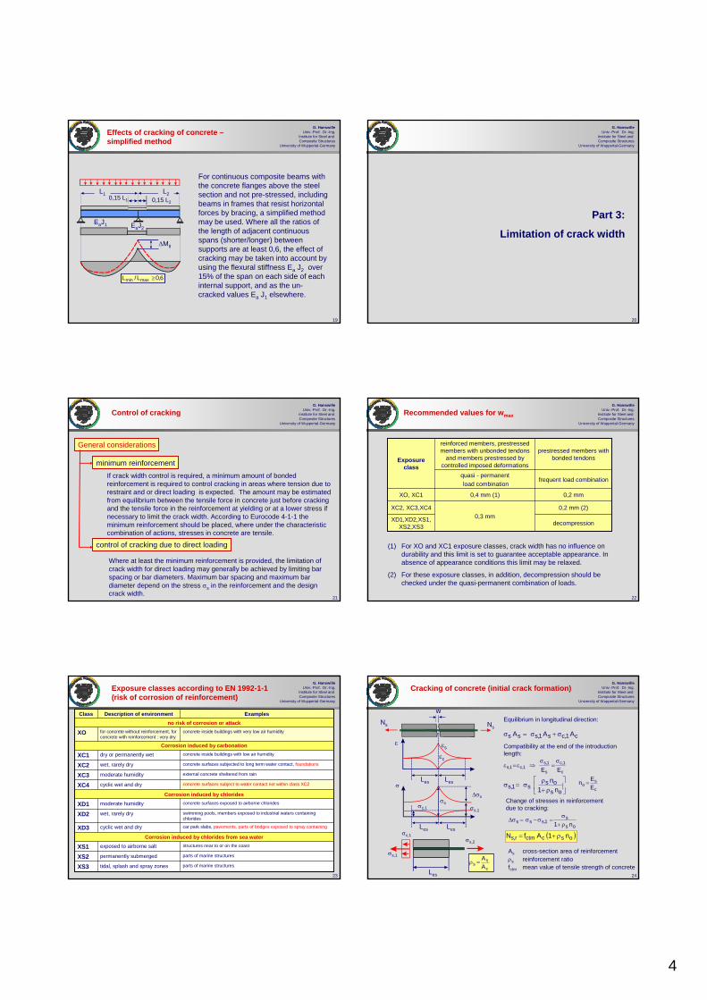
For continuous composite beams with the concrete flanges above the steel section and not pre-stressed, including beams in frames that resist horizontal forces by bracing, a simplified method may be used. Where all the ratios of the length of adjacent continuous spans (shorter/longer) between supports are at least 0,6, the effect of cracking may be taken into account by using the flexural stiffness Ea J2 over 15% of the span on each side of each internal support, and as the un-cracked values Ea J1 elsewhere.
20
G. HanswilleUniv.-Prof. Dr.-Ing.
Institute for Steel and Composite Structures
University of Wuppertal-Germany
Part 3:
Limitation of crack width
21
G. HanswilleUniv.-Prof. Dr.-Ing.
Institute for Steel and Composite Structures
University of Wuppertal-Germany
Control of cracking
General considerations
If crack width control is required, a minimum amount of bonded reinforcement is required to control cracking in areas where tension due to restraint and or direct loading is expected. The amount may be estimated from equilibrium between the tensile force in concrete just before cracking and the tensile force in the reinforcement at yielding or at a lower stress if necessary to limit the crack width. According to Eurocode 4-1-1 the minimum reinforcement should be placed, where under the characteristic combination of actions, stresses in concrete are tensile.
minimum reinforcement
control of cracking due to direct loading
Where at least the minimum reinforcement is provided, the limitation of crack width for direct loading may generally be achieved by limiting bar spacing or bar diameters. Maximum bar spacing and maximum bar diameter depend on the stress σs in the reinforcement and the design crack width.
22
G. HanswilleUniv.-Prof. Dr.-Ing.
Institute for Steel and Composite Structures
University of Wuppertal-Germany
Recommended values for wmax
decompressionXD1,XD2,XS1,XS2,XS3
0,2 mm (2)0,3 mm
XC2, XC3,XC4
0,2 mm0,4 mm (1)XO, XC1
frequent load combinationquasi - permanentload combination
prestressed members with bonded tendons
reinforced members, prestressedmembers with unbonded tendons
and members prestressed by controlled imposed deformations
Exposure class
(1) For XO and XC1 exposure classes, crack width has no influence ondurability and this limit is set to guarantee acceptable appearance. In absence of appearance conditions this limit may be relaxed.
(2) For these exposure classes, in addition, decompression should bechecked under the quasi-permanent combination of loads.
23
G. HanswilleUniv.-Prof. Dr.-Ing.
Institute for Steel and Composite Structures
University of Wuppertal-Germany
Exposure classes according to EN 1992-1-1(risk of corrosion of reinforcement)
parts of marine structurespermanently submergedXS2
car park slabs, pavements, parts of bridges exposed to spray containingcyclic wet and dryXD3Corrosion induced by chlorides from sea water
structures near to or on the coastexposed to airborne saltXS1
parts of marine structurestidal, splash and spray zonesXS3
swimming pools, members exposed to industrial waters containing chlorides
wet, rarely dryXD2
concrete surfaces exposed to airborne chlorides moderate humidityXD1Corrosion induced by chlorides
concrete surfaces subject to water contact not within class XC2cyclic wet and dryXC4
external concrete sheltered from rainmoderate humidityXC3
concrete surfaces subjected to long term water contact, foundationswet, rarely dryXC2
concrete inside buildings with low air humiditydry or permanently wetXC1Corrosion induced by carbonation
concrete inside buildings with very low air humidityfor concrete without reinforcement, for concrete with reinforcement : very dry
XOno risk of corrosion or attack
ExamplesDescription of environmentClass
24
G. HanswilleUniv.-Prof. Dr.-Ing.
Institute for Steel and Composite Structures
University of Wuppertal-Germany
Cracking of concrete (initial crack formation)
ε εs
εc
LesLes
NsNs
w
c
ss A
A=ρ
As cross-section area of reinforcementρs reinforcement ratiofctm mean value of tensile strength of concrete
c
so E
En =
c1,cs1,sss AAA σ+σ=σ
Equilibrium in longitudinal direction:
Compatibility at the end of the introduction length:
c
1,c
s
1,s1,c1,s EE
σ=
σ⇒ε=ε
⎥⎦
⎤⎢⎣
⎡ρ+
ρσ=σ
osos
s1,s n1n
os
s1,sss n1 ρ+
σ=σ−σ=σΔ
Change of stresses in reinforcement due to cracking:
LesLes
σsσs,1
σc,1
Δσs
σc,1
σs,1
σs,2
Les
σ
( )oscctmr,s n1AfN ρ+=

5
25
G. HanswilleUniv.-Prof. Dr.-Ing.
Institute for Steel and Composite Structures
University of Wuppertal-Germany
Cracking of concrete – introduction length
ε εs
εc
LesLes
NsNs
w
c
ss A
A=ρ
Us -perimeter of the barAs -cross-section areaρs -reinforcement ratioτsm -mean bond strength
c
so E
En =
4ddL
AUL2s
ssmses
sssmsesπ
σΔ=τπ
σΔ=τ
oss
1,sss n1 ρ+σ
=σ−σ=σΔ
Change of stresses in reinforcement due to cracking:
Equilibrium in longitudinal direction
LesLes
σsσs,1
σc,1
Δσs
σc,1
σs,1
σs,2
Les
τsm
σ
sosm
sses n1
14
dLρ+τ
σ=
introduction length LEs
crack width
)(L2w cmsmes ε−ε=
26
G. HanswilleUniv.-Prof. Dr.-Ing.
Institute for Steel and Composite Structures
University of Wuppertal-Germany
Determination of the mean strains of reinforcement and concrete in the stage of initial crack formation
ctmL
os
esm,s f8,1dx)x(
L1 Es
≈τ=τ ∫
Mean bond strength:
s
smsssm,s σΔ
σΔ−σ=β⇒σΔβ−σ=σ
∫ τ=σΔx
0s
ss dx)x(
U4)x(∫ σΔ=σΔ
esL
0s
essm dx)x(
L1
εεs
εc(x)
LesLes
NsNs
w
LesLes
σs σs,1
σc,1
Δσs
σ
εcr
Δεs,cr
Mean strains in reinforcement and concrete:
crm,c εβ=ε
Mean stress in the reinforcement:εs,m
εc,m
βΔσs
x
σs,m
σs(x)
εs(x)
cr,s2,sm,s εΔβ−ε=ε
27
G. HanswilleUniv.-Prof. Dr.-Ing.
Institute for Steel and Composite Structures
University of Wuppertal-Germany
Determination of initial crack width
ε εs(x)
εc(x)
LesLes
NsNs
w
LesLes
σsσs,1
σc,1
Δσs
σs
εcr
Δεs,crεs,m
εc,m
βΔσs
x
σs,m
crack width
)(L2w cmsmes ε−ε=
sosm
sses n1
14
dLρ+τ
σ=
2,scmm,s )1( εβ−=ε−ε
εs,2
sossms
2s
n11
E2d)1(w
ρ+τσβ−
=
with β= 0,6 for short term loading und β= 0,4 for long term loading
ctmsm f8,1≈τ
28
G. HanswilleUniv.-Prof. Dr.-Ing.
Institute for Steel and Composite Structures
University of Wuppertal-Germany
Maximum bar diameters acc. to EC4
-56450
468400
5810360
61012320
81216280
121620240
162532200
253240160
wk= 0,2wk= 0,3wk= 0,4
maximum bar diameter forσs
[N/mm2]
∗sd
sm,ct
s2s
sossm
s2s
Ef6d
n11
E2d)1(w σ
≈ρ+τ
σβ−=
Crack width w:
Maximum bar diameter for a required crack width w:
)1()n1(E2wd 2
s
sossms
β−σ
ρ+τ=
2s
so,ctmk*s
2s
soso,ctmk
*s
Efw6d
)1(
)n1(Ef6,3wd
σ≈
β−σ
ρ+=
With τsm= 1,8 fct,mo and the reference value for the mean tensile strength of concrete fctm,o= 2,9 N/mm2 follows:
β= 0,4 for long term loading and repeated loading
29
G. HanswilleUniv.-Prof. Dr.-Ing.
Institute for Steel and Composite Structures
University of Wuppertal-Germany
Crack width for stabilised crack formation
ε
εs(x)
εc(x)
sr,max= 2 Les
Ns
w
c
ctEf
s
2s2,s E
σ=ε
εs(x)- εc(x)
sr,min= Les
)(sw cmsmmax,r ε−ε=
Crack width for high bond bars
cctm
cm
ssctm
2,sss
ctmc2,sm,s
s2,sm,s
Ef
Ef
AEfA
β=ε
ρβ−ε=β−ε=ε
εΔβ−ε=ε
Mean strain of reinforcement and concrete:
β= 0,6 for short term loading
β= 0,4 for long term loading and repeated loading
)n1(Ef
E soss
ctm
s
scmsm ρ+
ρβ−
σ=ε−ε
30
G. HanswilleUniv.-Prof. Dr.-Ing.
Institute for Steel and Composite Structures
University of Wuppertal-Germany
Crack width for stabilised crack formation
ε
εs(x)
εc(x)
sr,max= 2 Les
Ns
w
c
ctEf
ss
2,s Eσ
=ε
εs(x)- εc(x)
sr,min= Les
sms
sctm
smscctm
es 4df
UAfL
τρ=
τ=
The maximum crack spacing sr,max in the stage of stabilised crack formation is twice the introduction length Les.
)(sw cmsmmax,r ε−ε=
⎟⎟⎠
⎞⎜⎜⎝
⎛ρ+
ρβ−
σρτ
= )n1(E
fE2
dfw soss
ctm
s
s
ssm
sctm
maximum crack width for sr= sr,max
β= 0,6 for short term loading
β= 0,4 for long term loading and repeated loading
6
31
G. HanswilleUniv.-Prof. Dr.-Ing.
Institute for Steel and Composite Structures
University of Wuppertal-Germany
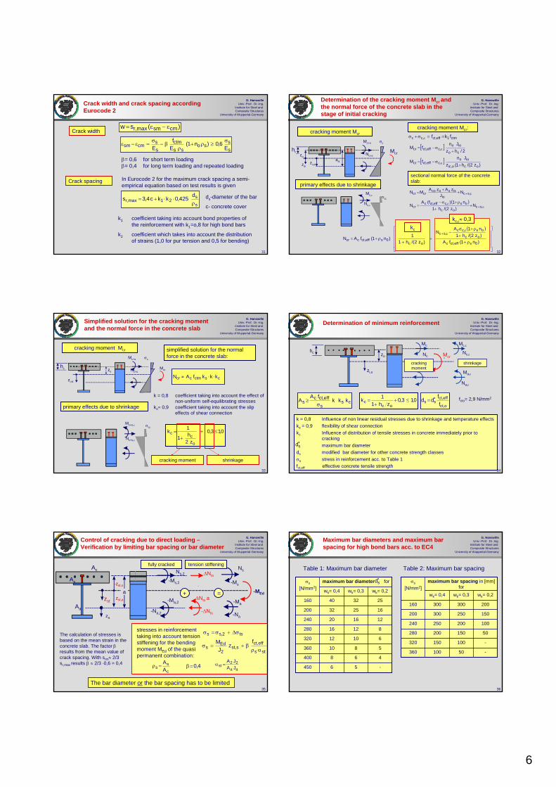
Crack width and crack spacing according Eurocode 2
)(sw cmsmmax,r ε−ε=Crack width
s
s21max,r
d425,0kkc4,3sρ
⋅⋅+= ds-diameter of the bar
c- concrete cover
In Eurocode 2 for the maximum crack spacing a semi-empirical equation based on test results is given
k1 coefficient taking into account bond properties of the reinforcement with k1=o,8 for high bond bars
k2 coefficient which takes into account the distribution of strains (1,0 for pur tension and 0,5 for bending)
ss
soss
ctmss
cmsm E6,0)n1(
Ef
Eσ≥ρ+
ρβ−σ=ε−ε
Crack spacing
β= 0,6 for short term loading β= 0,4 for long term loading and repeated loading
32
G. HanswilleUniv.-Prof. Dr.-Ing.
Institute for Steel and Composite Structures
University of Wuppertal-Germany
Determination of the cracking moment Mcr and the normal force of the concrete slab in the stage of initial cracking
cracking moment Mcr:
[ ]
[ ])z2/(h1(z
JnfM
2/hzJn
fM
oco,ic
ioo,ceff,ctcr
co
ioo,ceff,ctcr
+σ−=
+σ−=
ε
ε
( )ε+
ε
ε+
++
ρ+σ−=
++
=
,scoc
os,ceff,ctccr
,scio
issococrcr
N)z2/(h1
n1)f(AN
NJ
zAzAMNprimary effects due to shrinkage
cracking moment Mcr
hc
zio
zo
zi,st
Nc+s
Mc+s
Mc,ε
Mcr
Nc,ε
σc
σcε
ast
ctm1eff,ct,cc fkf ==σ+σ ε
sectional normal force of the concrete slab:
( )
⎥⎥⎥⎥
⎦
⎤
⎢⎢⎢⎢
⎣
⎡
ρ++
ρ+σ−
++
ρ+=
εε+
)n1(fA)z2/(h1n1A
N
)z2/(h11)n1(fAN
0seff,ctc
oc
os,cc,sc
oc0seff,ctccr
kc
kc,ε≈ 0,3
33
G. HanswilleUniv.-Prof. Dr.-Ing.
Institute for Steel and Composite Structures
University of Wuppertal-Germany
Simplified solution for the cracking moment and the normal force in the concrete slab
simplified solution for the normal force in the concrete slab:
primary effects due to shrinkage
cracking moment Mcr
hc zo
zi,st
Nc+s
Mc+s
Mc+s,ε
Mcr
Nc+s,ε
σc
σcε
csctmccr kkkfAN ⋅⋅≈
0,13,0
z2h1
1k
o
cc ≤+
+=
shrinkage
k = 0,8 coefficient taking into account the effect of non-uniform self-equilibrating stresses
ks= 0,9 coefficient taking into account the slip effects of shear connection
cracking moment
34
G. HanswilleUniv.-Prof. Dr.-Ing.
Institute for Steel and Composite Structures
University of Wuppertal-Germany
k = 0,8 Influence of non linear residual stresses due to shrinkage and temperature effects ks = 0,9 flexibility of shear connectionkc Influence of distribution of tensile stresses in concrete immediately prior to
crackingmaximum bar diameter
ds modified bar diameter for other concrete strength classes σs stress in reinforcement acc. to Table 1fct,eff effective concrete tensile strength
css
eff,ctcs kkk
fAA
σ≥ 0,13,0
zh11k
occ ≤+
+=
Mcr
Mc
NcNc,ε
Mc,ε
cracking moment
Na,ε
Ma,ε
shrinkage
hc zo
o,ct
eff,ctss f
fdd ∗=
∗sd
fcto= 2,9 N/mm2
zi,o
Determination of minimum reinforcement
35
G. HanswilleUniv.-Prof. Dr.-Ing.
Institute for Steel and Composite Structures
University of Wuppertal-Germany
stresses in reinforcement taking into account tension stiffening for the bending moment MEd of the quasi permanent combination:
c
ss A
A=ρ
sts
eff,cts,st
2
Eds
ts2,ss
fz
JM
αρβ+=σ
σΔ+σ=σ
aa
22st JA
JA=α4,0=β
Control of cracking due to direct loading –Verification by limiting bar spacing or bar diameter
Ns,2
-Ms,2
ΔNts
-Ma,2
-Na,2 -ΔNts
ΔNts azst,a
-zst,s
Ns
-Ms
-Ma
-Na
fully cracked tension stiffening
+ =zst
-MEd
za
a
The bar diameter or the bar spacing has to be limited
The calculation of stresses is based on the mean strain in the concrete slab. The factor βresults from the mean value of crack spacing. With srm≈ 2/3 sr,max results β ≈ 2/3 ·0,6 = 0,4
Ac
As
Aa
36
G. HanswilleUniv.-Prof. Dr.-Ing.
Institute for Steel and Composite Structures
University of Wuppertal-Germany
Maximum bar diameters and maximum bar spacing for high bond bars acc. to EC4
-56450
468400
5810360
61012320
81216280
121620240
162532200
253240160
wk= 0,2wk= 0,3wk= 0,4
maximum bar diameter forσs
[N/mm2]
-50100360
-100150320
50150200280
100200250240
150250300200
200300300160
wk= 0,2wk= 0,3wk= 0,4
maximum bar spacing in [mm] for
σs
[N/mm2]
∗sd
Table 1: Maximum bar diameter Table 2: Maximum bar spacing

7
37
G. HanswilleUniv.-Prof. Dr.-Ing.
Institute for Steel and Composite Structures
University of Wuppertal-Germany
Direct calculation of crack width w for composite sections based on EN 1992-2
zst
-zst,s
As σs,
MEd
sts
eff,cts,st
stEd
sf
zJ
Mαρ
β+=σ
aa
ststst JA
JA=α
c
ss A
A=ρ 4,0=β
)(sw cmsmmax,r ε−ε=
Ns
-Ms
-Ma
-Na
ss
soss
ctmss
cmsm E6,0)n1(
Ef
Eσ≥ρ+
ρβ−σ=ε−ε
ss
max,rd34,0c4,3sρ
+=
crack width for high bond bars:
c - concrete cover of reinforcement38
G. HanswilleUniv.-Prof. Dr.-Ing.
Institute for Steel and Composite Structures
University of Wuppertal-Germany
Stresses in reinforcement in case of bonded tendons – initial crack formation
As, ds
Ap, dp
Les
Lep
τsmτpm
Δσp
σs=σs1+Δσs
Equilibrium at the crack:
)n1(AfNAA totoceff,ctppss ρ+==σΔ+σEquilibrium in longitudinal direction:
s,esmsss LdA τπ=σ
eppmppp LdA τπ=σΔ
Compatibility at the crack:
epp
1ppes
s
1ssps L
EL
EσΔ−σΔ
=σ−σ
⇒δ=δ
v
s
sm
pm1
p1s
1p
p1ss
dd
AAN
AAN
τ
τ=ξ
ξ+
ξ=σΔ
ξ+=σ
N
σs,1
Δσp1
Stresses:
With Es≈Ep and σs1=Δσp1=0 results:Δσs
σp
σp=σpo+σp1+Δσp
39
G. HanswilleUniv.-Prof. Dr.-Ing.
Institute for Steel and Composite Structures
University of Wuppertal-Germany
Stresses in reinforcement for final crack formation
Maximum crack spacing:
p
1p2p2,p
s
1s2s2sps E
)(E
)( σΔ−σΔβ−σΔ=
σ−σβ−σ=δ=δ
[ ]
)AA(2Afd
s
dndn2
sAf
p2
ssm
ceff,ctsmax,r
pppmsssmmax,r
cct
ξ+τ=
πτ+πτ=
Compatibility at the crack:
pmp
pmax,r1p2psm
s
smax,r1s2s A
U2
sAU
2s
τ=σ−στ=σ−σ
Equilibrium in longitudinal direction:
Equilibrium at the crack:
p2ps2so AAPN σΔ+σ=−
σs
As, ds
Ap, dp
σs2
Δσp2
Δσp2
Δσp1
σs1
sr,max
σcσc=fct,eff
x
mean crack spacing: sr,m≈2/3 sr,max
40
G. HanswilleUniv.-Prof. Dr.-Ing.
Institute for Steel and Composite Structures
University of Wuppertal-Germany
Determination of stresses in composite sections with bonded tendons
⎥⎥⎦
⎤
⎢⎢⎣
⎡
ρξ
−ρ
−σ=⎥⎥⎦
⎤
⎢⎢⎣
⎡
ξ+
ξ−
+−σ=σΔ
⎥⎦
⎤⎢⎣
⎡ρ
−ρ
+σ=⎥⎥⎦
⎤
⎢⎢⎣
⎡
+−
ξ++σ=σ
eff
21
toteff,ct
*s
p21s
c21
ps
ceff,ct
*sp
toteffeff,ct
*s
ps
c
p21s
ceff,ct
*ss
1f4,0AA
AAA
Af4,0
11f4,0AA
AAA
Af4,0
c
p21s
eff
c
pstot
AAA
AAA
ξ+=ρ
+=ρ
Stresses σ*s in reinforcement
at the crack location neglecting different bond behaviour of reinforcement and tendons:
sttot
ctms,st
st
Ed*s
fzJ
Mαρ
β+=σ
aa
ststst JA
JA=α 4,0=β
zst
-zst,s
AsAp σs,σp
MEd
Stresses in reinforcement taking into account the different bond behaviour:
41
G. HanswilleUniv.-Prof. Dr.-Ing.
Institute for Steel and Composite Structures
University of Wuppertal-Germany
Part 4:
Deformations
42
G. HanswilleUniv.-Prof. Dr.-Ing.
Institute for Steel and Composite Structures
University of Wuppertal-Germany
Deflections
Deflections due to loading applied to the composite member should be calculated using elastic analysis taking into account effects from
- cracking of concrete,
- creep and shrinkage,
- sequence of construction,
- influence of local yielding of structural steel at internal supports,
- influence of incomplete interaction.
L1 L2
ΔMEaJ1
0,15 L1 0,15 L2
EaJ2
Effects of cracking of concrete
Sequence of construction
F
F
steel member
composite member
gc
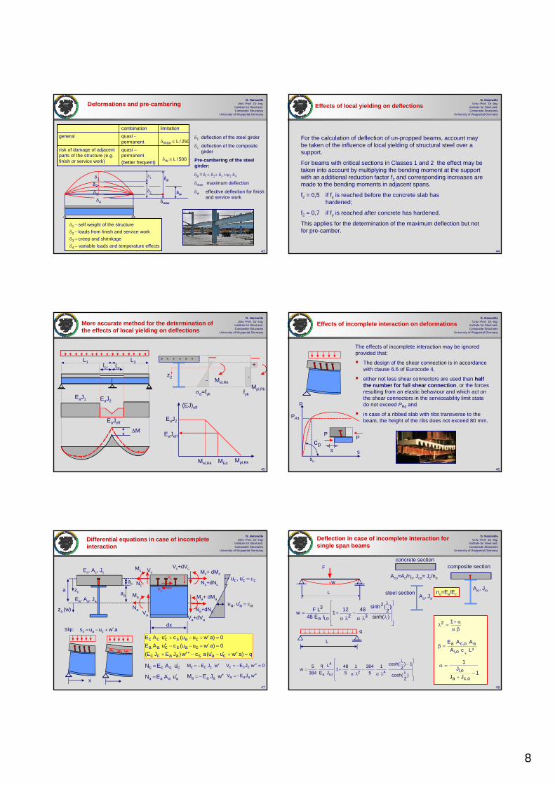
8
43
G. HanswilleUniv.-Prof. Dr.-Ing.
Institute for Steel and Composite Structures
University of Wuppertal-Germany
Deformations and pre-cambering
δ1δ2
δ3
δ4
δ1 – self weight of the structureδ2 – loads from finish and service workδ3 – creep and shrinkageδ4 – variable loads and temperature effects
δp
δmax
δw
quasi –permanent(better frequent)
risk of damage of adjacent parts of the structure (e.g. finish or service work)
quasi -permanent
generallimitationcombination
250/Lmax ≤δ
500/Lw ≤δ
δ1
δc
δ1 deflection of the steel girder
δc deflection of the composite girder
Pre-cambering of the steel girder:
δp = δ1+ δ2+ δ3 +ψ2 δ4
δmax maximum deflection
δw effective deflection for finish and service work
44
G. HanswilleUniv.-Prof. Dr.-Ing.
Institute for Steel and Composite Structures
University of Wuppertal-Germany
Effects of local yielding on deflections
For the calculation of deflection of un-propped beams, account may be taken of the influence of local yielding of structural steel over a support.
For beams with critical sections in Classes 1 and 2 the effect may be taken into account by multiplying the bending moment at the support with an additional reduction factor f2 and corresponding increases are made to the bending moments in adjacent spans.
f2 = 0,5 if fy is reached before the concrete slab has hardened;
f2 = 0,7 if fy is reached after concrete has hardened.
This applies for the determination of the maximum deflection but not for pre-camber.
45
G. HanswilleUniv.-Prof. Dr.-Ing.
Institute for Steel and Composite Structures
University of Wuppertal-Germany
More accurate method for the determination of the effects of local yielding on deflections
EaJ1
ΔM
EaJ2
z2 Mel,Rk
σa=fyk fyk
--
+
(EJ)eff
EaJ2
Mel,Rk
Mpl,Rk
Mpl,RkMEd
EaJeff
L1 L2lcr lcr
EaJeff
46
G. HanswilleUniv.-Prof. Dr.-Ing.
Institute for Steel and Composite Structures
University of Wuppertal-Germany
Effects of incomplete interaction on deformations
P
ss
PPcD
su
PRd
The effects of incomplete interaction may be ignored provided that:
The design of the shear connection is in accordance with clause 6.6 of Eurocode 4,
either not less shear connectors are used than half the number for full shear connection, or the forces resulting from an elastic behaviour and which act on the shear connectors in the serviceability limit state do not exceed PRd and
in case of a ribbed slab with ribs transverse to the beam, the height of the ribs does not exceed 80 mm.
47
G. HanswilleUniv.-Prof. Dr.-Ing.
Institute for Steel and Composite Structures
University of Wuppertal-Germany
Differential equations in case of incomplete interaction
Nc
Na
Ma
Mc
Va
Nc+dNc
Na+dNa
Ma+ dMa
Mc+ dMc
Va+dVadx
a
za (w)
zc
x
Ec, Ac, Jc
Ea, Aa, Ja
vL
vL
awuus cav ′+−=
VcVc+dVc
aa
ac
Slip:
ccc u,u ε=′
aaa u,u ε=′
q)awuu(acw)JEJE(0)awuu(cuAE0)awuu(cuAE
casaacc
cascaa
casccc
=′′+′−′−′′′′+
=′+−−′′=′+−+′′
cccc uAEN ′=
aaaa uAEN ′=
wJEM ccc ′′−=
wJEM aaa ′′−=
0wJEV ccc ≈′′′−=
wJEV aaa ′′′−=
48
G. HanswilleUniv.-Prof. Dr.-Ing.
Institute for Steel and Composite Structures
University of Wuppertal-Germany
⎥⎥⎥
⎦
⎤
⎢⎢⎢
⎣
⎡
λ
−λ
λα−
λα+=
)2
cosh(
1)2
cosh(15
38415
481JELq
3845w 42o,ia
4
q
1JJ
J1
o,ca
o,i −+
=α
²LcAAAE
so,i
ao,ca=β
βαα+
=λ12
F
L
⎥⎥⎥
⎦
⎤
⎢⎢⎢
⎣
⎡
λ
λ
λα−
λα+=
)sinh(
)2
(sinh48121IE48
LFw2
32o,ia
3
L
Deflection in case of incomplete interaction for single span beams
Aio, Jio
composite sectionconcrete section
steel section Aa, Ja
Aco=Ac/no, Jco= Jc/no
no=Ea/Ec
w

9
49
G. HanswilleUniv.-Prof. Dr.-Ing.
Institute for Steel and Composite Structures
University of Wuppertal-Germany
Mean values of stiffness of headed studs
P
ss
PP
cD
su
PRd
eLnt=2
Rd
uD P
sC =spring constant per stud:
spring constant of the shearconnection: L
tDs e
nCc =
type of shear connection
1500headed stud ∅ 22mmwith Holorib-sheeting and one stud per rib
1250headed stud ∅ 19mmwith Holorib-sheeting and one stud per rib
3500headed studs ∅ 25mmin solid slab
3000headed stud ∅ 22mmin solid slabs
2500headed stud ∅ 19mmin solid slabs
]cm/kN[CD
cs
50
G. HanswilleUniv.-Prof. Dr.-Ing.
Institute for Steel and Composite Structures
University of Wuppertal-Germany
Simplified solution for the calculation of deflections in case of incomplete interaction
( ) πξ=ξ sinqq
L
Lx
=ξ
za
zc
Ec, Ac, Jc
Ea, Aa, Ja
a
Nc
Na
Ma
Mc 2
aeff,c
aeff,cao,ceff,io a
AAAA
JJJ+
++=
The influence of the flexibility of the shear connection is taken into account by a reduced value for the modular ratio.
eff,ioa4
4
2
ccmoaa
aaccmoaaccm
4
4
o JE1Lq
aAEAE
AEAEJEJE
1Lqwπ
=
β+
β++π
=
)1(nn soeff,o β+=s
2ccm
2
s cLAEπ
=β
eff,o
ceff,c n
AA =
effective modular ratio for the concrete slab
εa
εc
51
G. HanswilleUniv.-Prof. Dr.-Ing.
Institute for Steel and Composite Structures
University of Wuppertal-Germany
Comparison of the exact method with the simplified method
w/wc
L [m]1,1
1,0
1,2
1,3
1,4
1,5
5,0 10,0 15,0 20,0
w/wc
L [m]
1,1
1,0
1,15
1,2
1,25
5,0 10,0 15,0 20,0
cD = 2000 KN/cm
q
L
w
beff
5199
450 mm
Ecm = 3350 KN/cm²
exact solutionsimplified solution with no,eff
1,05 η=0,8
η=0,4
η=0,8
η=0,4
cD = 1000 KN/cm
wo- deflection in case of neglecting effects from slip of shear connection
η degree of shear connection
52
G. HanswilleUniv.-Prof. Dr.-Ing.
Institute for Steel and Composite Structures
University of Wuppertal-Germany
1875 1875
1875 18753750
7500
F
F
F/2 F/2
load case 2
load case 1
δ[mm]
F [kN]
20 40 60
50
100
150
200
0
Deflection at midspan
1500
445
270
175
50
IPE 270
load case 2
load case 1
Deflection in case of incomplete interaction-comparison with test results
53
G. HanswilleUniv.-Prof. Dr.-Ing.
Institute for Steel and Composite Structures
University of Wuppertal-Germany
780
50125Load case 2F=145 kN
Load case 1F= 60 kN
second moment of area
cm4
19,4 (97%)11,7 (106%)Jio,eff= 21.486,0Theoretical value, taking into account flexibility of shear connection
12,9 (65%)7,8 (71%)Jio= 32.387,0Theoretical value, neglecting flexibility of shear connection
20,0 (100 %)11,0 (100%)-Test
Deflection at midspan in mm
F F
s
s[mm]10 20 30 40
40
80
120
160 push-out test
Deflection in case of incomplete interaction-Comparison with test results
54
G. HanswilleUniv.-Prof. Dr.-Ing.
Institute for Steel and Composite Structures
University of Wuppertal-Germany
Part 5:
Limitation of stresses

10
55
G. HanswilleUniv.-Prof. Dr.-Ing.
Institute for Steel and Composite Structures
University of Wuppertal-Germany
Limitation of Stresses
σc MEd
σa
+
+
-
-
MEd
σa
σs
+
-
PEd ≤ ks PRd
σEd ≤ kc fck
σEd ≤ ks fsk
σEd ≤ ka fyk
stress limit
ks = 0,75characteristicheaded studs
kc= 0,60characteristicconcrete
ks = 0,80characteristicreinforcement
ka = 1,00characteristicstructural steel
recommended values ki
combination
Stress limitation is not required for beams if in the ultimate limit state,
- no verification of fatigue is required and
- no prestressing by tendons and /or
- no prestressing by controlled imposed deformations is provided.
56
G. HanswilleUniv.-Prof. Dr.-Ing.
Institute for Steel and Composite Structures
University of Wuppertal-Germany
composite section steel sectiongc
MEd(x)
VEd
MEd
VEd(x)
+
-+
bc
beff
y
z
ziox
Concentrated longitudinal shear force at sudden change of cross-section
Nc
vL,Ed,max
Lv=beff
effioca
ioeff,cEdmax,Ed,L bJE/E
zAM2v =
Ac,eff
longitudinal shear forces
+-
Local effects of concentrated longitudinal shear forces
57
G. HanswilleUniv.-Prof. Dr.-Ing.
Institute for Steel and Composite Structures
University of Wuppertal-Germany
z
y
bc=10 m
300
500x2014x2000
800x60
δ
P
CD = 3000 kN/cmper stud
L = 40 m
gc,d
cross-section
FE-Model
system
shear connectors
Local effects of concentrated longitudinal shear forces
58
G. HanswilleUniv.-Prof. Dr.-Ing.
Institute for Steel and Composite Structures
University of Wuppertal-Germany
Ultimate limit state - longitudinal shear forces
FE-Model:
FE-Model
L = 40 m
x
s
P
cD
s
P
cD
EN 1994-2
x [cm]
ULS
59
G. HanswilleUniv.-Prof. Dr.-Ing.
Institute for Steel and Composite Structures
University of Wuppertal-Germany
200 400 600 800 1000 1200 1400 1600 1800 2000
-4000
-3500
-3000
-2500
-2000
-1500
-1000
-500
0
500
Serviceability limit state - longitudinal shear forces
EN 1994-2
FE-Model:
FE-Model
L = 40 m
vL,Ed[kN/m]
x [cm]
x
s
P
cD
s
P
cD
SLS
60
G. HanswilleUniv.-Prof. Dr.-Ing.
Institute for Steel and Composite Structures
University of Wuppertal-Germany
Part 6:
Vibrations

11
61
G. HanswilleUniv.-Prof. Dr.-Ing.
Institute for Steel and Composite Structures
University of Wuppertal-Germany
Vibration- General
EN 1994-1-1: The dynamic properties of floor beams should satisfy the criteria in EN 1990,A.1.4.4
EN 1990, A1.4.4: To achieve satisfactory vibration behaviour of buildings and their structural members under serviceability conditions, the following aspects, among others, should be considered:
the comfort of the user
the functioning of the structure or its structural members
Other aspects should be considered for each project and agreed with the client
62
G. HanswilleUniv.-Prof. Dr.-Ing.
Institute for Steel and Composite Structures
University of Wuppertal-Germany
Vibration - General
EN 1990-A1.4.4:
For serviceability limit state of a structure or a structural member not to be exceeded when subjected to vibrations, the natural frequency of vibrations of the structure or structural member should be kept above appropriate values which depend upon the function of the building and the source of the vibration, and agreed with the client and/or the relevant authority.
Possible sources of vibration that should be considered include walking, synchronised movements of people, machinery, ground borne vibrations from traffic and wind actions. These, and other sources, should be specified for each project and agreed with the client.
Note in EN 1990-A.1.4.4: Further information is given in ISO 10137.
63
G. HanswilleUniv.-Prof. Dr.-Ing.
Institute for Steel and Composite Structures
University of Wuppertal-Germany
xk
ls
Span length
xls
time tF(x,t)
F(x,t)
tsxk
tk
Vibration – Example vertical vibration due to walking persons
1,755,5> 3,2fast running (sprint)
1,303,3∼2,5slow running (jog)
1,002,2∼2,3fast walk0,751,5∼2,0normal walk0,61,1∼1,7slow walk
stride length
ls[m]
forward speedvs = fs ls[m/s]
pacing rate
fs [Hz]
The pacing rate fs dominates the dynamic effects and the resulting dynamic loads. The speed of pedestrian propagation vs is a function of the pacing rate fs and the stride length ls.
64
G. HanswilleUniv.-Prof. Dr.-Ing.
Institute for Steel and Composite Structures
University of Wuppertal-Germany
Vibration –vertical vibrations due to walking of one person
time t
Fi(t)left foot
right foot
F(t)
both feet
1. step 2. step 3. step
ts=1/fs
( )⎥⎥⎦
⎤
⎢⎢⎣
⎡Φ−πα+= ∑
=
3
1nnsno tfn2sin1G)t(F
Go weight of the person (800 N)αn coefficient for the load component of n-th harmonicn number of the n-th harmonicfs pacing rateΦn phase angle oh the n-th harmonic
During walking, one of the feet is always in contact with the ground. The load-time function can be described by a Fourier series taking into account the 1st, 2nd and 3rd harmonic.
α1=0,4-0,5 Φ1=0
α2=0,1-0,25 Φ2=π/2
α3=0,1-0,15 Φ3=π/2
Fourier-coefficients and phase angles:
65
G. HanswilleUniv.-Prof. Dr.-Ing.
Institute for Steel and Composite Structures
University of Wuppertal-Germany
Vibration – vertical vibrations due to walking of persons
( )sE v/Lf
gen
namax e1
MFka δ−−
δπ
=
Mgen
F(t)
cδ
w(t)maximum acceleration a, vertical deflection w and maximum velocity v
acceleration
Emax
2E
max
f2av
)f2(aw
π=
π=
fE natural frequencyFn load component of n-th harmonicδ logarithmic damping decrementvs forward speed of the personka factor taking into account the different
positions xk during walking along the beamMgen generated mass of the system
(single span beam: Mgen=0,5 m L)
m
L
Fn(t)xk
w(xk,t)
L/2ka Fn(t)
w(t)
( )tfE
gen
na Ee1)tf2(sin
MFk)t(w δ−−π
δπ
=sv
Lt =
66
G. HanswilleUniv.-Prof. Dr.-Ing.
Institute for Steel and Composite Structures
University of Wuppertal-Germany
Logarithmic damping decrement
For the determination of the maximum acceleration the damping coefficient ζ or the logarithmic damping decrement δmust be determined. Values for composite beams are given in the literature. The logarithmic damping decrement is a function of the used materials, the damping of joints and bearings or support conditions and the natural frequency.
For typical composite floor beams in buildings with natural frequencies between 3 and 6 Hz the following values for the logarithmic damping decrement can be assumed:
δ=0,10 floor beams without not load-bearing inner walls
δ=0,15 floor beams with not load-bearing inner walls
1
2
3
4
5
6
Dampingratioξ [%]
3 6 9 12fE [Hz]
ξπ=δ 2
results of measurements in buildings
with finishes
without finishes

12
67
G. HanswilleUniv.-Prof. Dr.-Ing.
Institute for Steel and Composite Structures
University of Wuppertal-Germany
Vibration –vertical vibrations due to walking of persons
People in office buildings sitting or standing many hours are very sensitive to building vibrations. Therefore the effects of the second and third harmonic of dynamic load-time function should be considered, especially for structure with small mass and damping. In case of walking the pacing rate is in the rage of 1.7 to 2.4 Hz. The verification can be performed by frequency tuning or by limiting the maximum acceleration.
In case of frequency tuning for composite structures in office buildings the natural frequency normally should exceed 7,5 Hz if the first, second and third harmonic of the dynamic load-time function can cause significant acceleration.
Otherwise the maximum acceleration or velocity should be determined and limited to acceptable values in accordance with ISO 10137
F(t)/Go
( )∑=
Φ−π+=3
1nnsno tfn2sinFG)t(F
0,4
0,2
2,0 4,0 6,0 8,0
0,1
fs=1,5-2,5 Hz
2fs=3,0-5,0 Hz
3fs=4,5-7,5 Hz
68
G. HanswilleUniv.-Prof. Dr.-Ing.
Institute for Steel and Composite Structures
University of Wuppertal-Germany
Limitation of acceleration-recommended values acc. to ISO 10137
1 5 10 50 100
0,01
0,05
0,1
acceleration [m/s2]
frequency [Hz]
0,005 basic curve ao
Multiplying factors Ka for the basic curve
Residential (flats, hospitals) Ka=1,0Quiet office Ka=2-4General office (e. g. schools) Ka=4
ao Kaa ≤
natural frequency of typical compositebeams

COMPOSITE COLUMNS
G. Hanswille Bergische Universität Wuppertal


1
1
G. HanswilleUniv.-Prof. Dr.-Ing.
Institute for Steel and Composite Structures
University of Wuppertal-Germany
Composite Columns
Institute for Steel and Composite StructuresUniversity of Wuppertal
Germany
Univ. - Prof. Dr.-Ing. Gerhard Hanswille
Eurocode 4
EurocodesBackground and Applications
Dissemination of information for training18-20 February 2008, Brussels
2
G. HanswilleUniv.-Prof. Dr.-Ing.
Institute for Steel and Composite Structures
University of Wuppertal-Germany
Part 1: Introduction
Part 2: General method of design
Part 3: Plastic resistance of cross-sections and interaction curve
Part 4: Simplified design method
Part 5: Special aspects of columns with inner core profiles
Part 6: Load introduction and longitudinal shear
Contents
3
G. HanswilleUniv.-Prof. Dr.-Ing.
Institute for Steel and Composite Structures
University of Wuppertal-Germany
Part 1: Introduction
4
G. HanswilleUniv.-Prof. Dr.-Ing.
Institute for Steel and Composite Structures
University of Wuppertal-Germany
Composite columns
concrete filled hollow
sections
partially concrete encased sections
concrete encased sections
5
G. HanswilleUniv.-Prof. Dr.-Ing.
Institute for Steel and Composite Structures
University of Wuppertal-Germany
Special Cross-Sections
hollow sections with additional inner profiles
partially concrete encased sections
6
G. HanswilleUniv.-Prof. Dr.-Ing.
Institute for Steel and Composite Structures
University of Wuppertal-Germany
advantages:high bearing resistance
high fire resistance
economical solution with regard to material costs
disadvantages:high costs for formwork
difficult solutions for connections with beams
difficulties in case of later strengthening of the column
in special case edge protection is necessary
Concrete encased sections

2
7
G. HanswilleUniv.-Prof. Dr.-Ing.
Institute for Steel and Composite Structures
University of Wuppertal-Germany
advantages:
high bearing resistance, especially in case of welded steel sectionsno formwork simple solution for joints and load introductioneasy solution for later strengthening and additional later jointsno edge protection
disadvantages:lower fire resistance in comparison with concrete encased sections.
Partially concrete encased sections
8
G. HanswilleUniv.-Prof. Dr.-Ing.
Institute for Steel and Composite Structures
University of Wuppertal-Germany
Casting of partially concrete encased sections
reinforcing pocket 1
casting pocket 1
turning the steel profile
reinforcing pocket 2
casting pocket 2
9
G. HanswilleUniv.-Prof. Dr.-Ing.
Institute for Steel and Composite Structures
University of Wuppertal-Germany
advantages:
high resistance and slender columns advantages in case of biaxial bendingno edge protection
disadvantages :high material costs for profilesdifficult castingadditional reinforcement is needed for fire resistance
Concrete filled hollow sections
10
G. HanswilleUniv.-Prof. Dr.-Ing.
Institute for Steel and Composite Structures
University of Wuppertal-Germany
H ≈ 0,2L
hole for vent
Opening for casting
Casting from the top
Pumping in vertical
direction
pumping in inclined position
hole for vent
e ≤ 5mOutside compactor
L
Casting of concrete in case of concrete filled hollow sections
11
G. HanswilleUniv.-Prof. Dr.-Ing.
Institute for Steel and Composite Structures
University of Wuppertal-Germany
advantages:
extreme high bearing resistance in combination with slender columnsconstant cross section for all stories is possible in high rise buildingshigh fire resistance and no additional reinforcementno edge protection
disadvantages:high material costsdifficult casting
Concrete filled hollow sections with additional inner profiles
12
G. HanswilleUniv.-Prof. Dr.-Ing.
Institute for Steel and Composite Structures
University of Wuppertal-Germany
Composite columns with hollow sections and additional inner core-profiles
CommerzbankFrankfurt
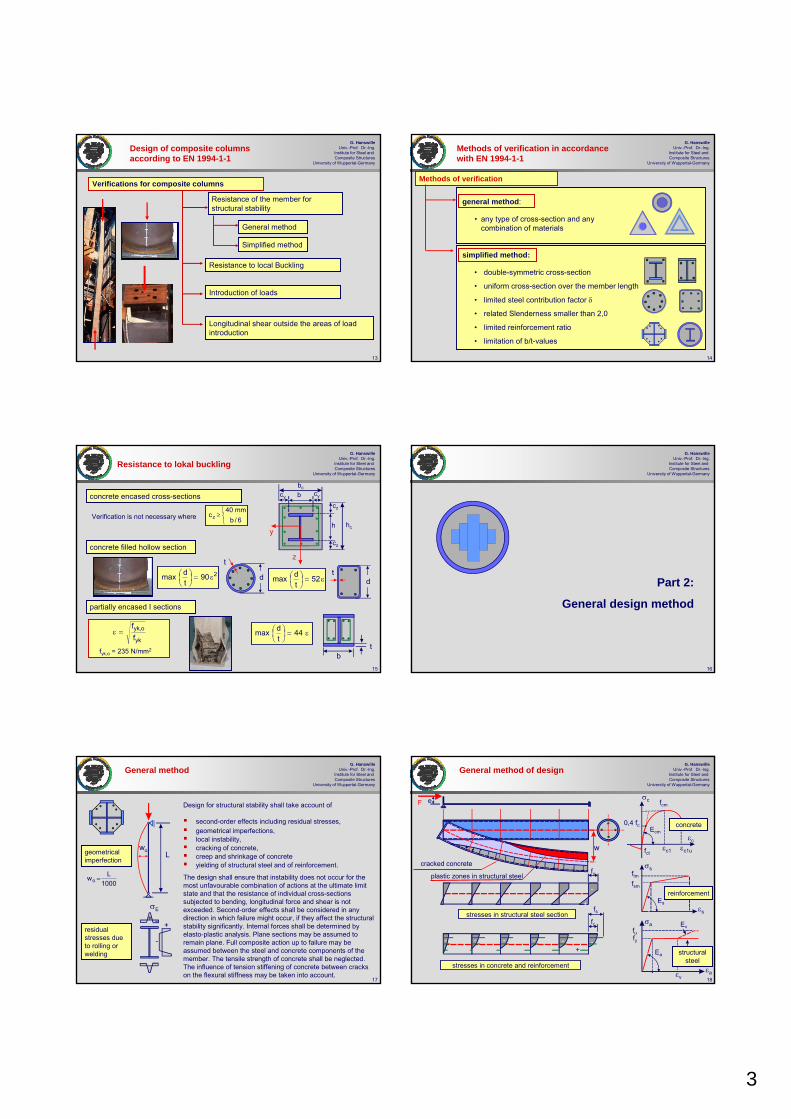
3
13
G. HanswilleUniv.-Prof. Dr.-Ing.
Institute for Steel and Composite Structures
University of Wuppertal-Germany
Resistance of the member for structural stability
Resistance to local Buckling
Introduction of loads
Longitudinal shear outside the areas of load introduction
General method
Simplified method
Verifications for composite columns
Design of composite columns according to EN 1994-1-1
14
G. HanswilleUniv.-Prof. Dr.-Ing.
Institute for Steel and Composite Structures
University of Wuppertal-Germany
general method:
simplified method:
• double-symmetric cross-section
• uniform cross-section over the member length
• limited steel contribution factor δ
• related Slenderness smaller than 2,0
• limited reinforcement ratio
• limitation of b/t-values
• any type of cross-section and any combination of materials
Methods of verification
Methods of verification in accordance with EN 1994-1-1
15
G. HanswilleUniv.-Prof. Dr.-Ing.
Institute for Steel and Composite Structures
University of Wuppertal-Germany
Verification is not necessary where
concrete encased cross-sections
partially encased I sections
concrete filled hollow section
bt
t
dd tε=⎟
⎠⎞
⎜⎝⎛ 52
tdmax
290tdmax ε=⎟
⎠⎞
⎜⎝⎛
ε=⎟⎠⎞
⎜⎝⎛ 44
tdmax
yk
o,yk
ff
=ε
fyk,o = 235 N/mm2
bc
hc
b
h
cy cy
cz
cz
y
z
⎩⎨⎧
≥6/b
mm40cz
Resistance to lokal buckling
16
G. HanswilleUniv.-Prof. Dr.-Ing.
Institute for Steel and Composite Structures
University of Wuppertal-Germany
Part 2:
General design method
17
G. HanswilleUniv.-Prof. Dr.-Ing.
Institute for Steel and Composite Structures
University of Wuppertal-Germany
geometrical imperfection
wo
1000Lwo =
L
σE
+ -residual stresses due to rolling or welding
+
-
General method
Design for structural stability shall take account of
second-order effects including residual stresses, geometrical imperfections, local instability, cracking of concrete, creep and shrinkage of concrete yielding of structural steel and of reinforcement.
The design shall ensure that instability does not occur for the most unfavourable combination of actions at the ultimate limit state and that the resistance of individual cross-sections subjected to bending, longitudinal force and shear is not exceeded. Second-order effects shall be considered in any direction in which failure might occur, if they affect the structural stability significantly. Internal forces shall be determined by elasto-plastic analysis. Plane sections may be assumed to remain plane. Full composite action up to failure may be assumed between the steel and concrete components of the member. The tensile strength of concrete shall be neglected. The influence of tension stiffening of concrete between cracks on the flexural stiffness may be taken into account.
18
G. HanswilleUniv.-Prof. Dr.-Ing.
Institute for Steel and Composite Structures
University of Wuppertal-Germany
General method of design
F
plastic zones in structural steel
e
cracked concrete
stresses in structural steel section
stresses in concrete and reinforcement
fy
fc
-
-
-
+
+
- - -
-
w
fs
εc
εs
εa
fcm
0,4 fcEcm
εc1uεc1fct
σc
σs
fsm
ftm
Es
Ea
Ev
εv
σa
concrete
reinforcement
structural steel
fyfu
--

4
19
G. HanswilleUniv.-Prof. Dr.-Ing.
Institute for Steel and Composite Structures
University of Wuppertal-Germany
elasto - plastic resistance of the cross-section
elasto-plastic full plasticfcm
fsm
fyfsm
fsm
- - -+
fy
MRu,N
NRuNRu
Mpl,u,,N
R,pl
RMM
1,0
R,pl
RNN
1,0
A
B
A B
R,pl
RuNN
III
R,pl
N,RuMM
F
w+wo
M=F (w+wo)
Case I: ultimate load of the system is reached due to elasto-plastic failure of the critical cross-section
Case II: stability failure before reaching the elasto-plastic resistance of the cross-section.
20
G. HanswilleUniv.-Prof. Dr.-Ing.
Institute for Steel and Composite Structures
University of Wuppertal-Germany
Typical load-deformation behaviour of composite columns in tests
F [kN]
Deflection w [mm]
e
e=100mm
e=160mm
e=130mm
0 20 40 60 80 100
1600
1200
800
400
F
wA
B
C
concrete encased section and bending about the strong axis:Failure due to exceeding the ultimate strain in concrete, buckling of longitudinal reinforcement and spalling of concrete.
concrete encased section and bending about the weak axis :Failure due to exceeding the ultimate strain in concrete.
concrete filled hollow section:cross-section with high ductility and rotation capacity. Fracture of the steel profile in the tension zone at high deformations and local buckling in the compression zone of the structural steel section.
A
F
B
C
21
G. HanswilleUniv.-Prof. Dr.-Ing.
Institute for Steel and Composite Structures
University of Wuppertal-Germany
M
N
NEd
MEd
Ed
Rpl,d
Rpl,mEd
wo=L/1000 wo
w
d,pl
m,plR R
R=γ
e
E
λu Ed
wu
Verification λu ≥ γR
λu : amplification factor for ultimate system capacity
εc
fcm
0,4 fc Ecm
εc1uεc1fct
σc
concrete
εs
σs
fsm
ftm
Es
reinforcementεa
Ea
εv
σa
structural steel
fyfu
+
+
-
-
+ -
geometrical Imperfection
Residual stresses
Ev
General Method – Safety concept based on DIN 18800-5 (2004) and German
national Annex for EN 1994-1-1
22
G. HanswilleUniv.-Prof. Dr.-Ing.
Institute for Steel and Composite Structures
University of Wuppertal-Germany
0,5 1,0 1,5 2,0
0,5
1,0
Composite columns for the central station in Berlin
-
χbuckling curve a
buckling curve b
buckling curve c
buckling curve d
800550
1200
700
t=25mm
t=50mmS355
S235
Residual stresses
λ
23
G. HanswilleUniv.-Prof. Dr.-Ing.
Institute for Steel and Composite Structures
University of Wuppertal-Germany
Part IV-3:
Plastic resistance of cross-sections and interaction curve
24
G. HanswilleUniv.-Prof. Dr.-Ing.
Institute for Steel and Composite Structures
University of Wuppertal-Germany
Resistance of cross-sections
sdscdcydaRd,pl
Rd,plsRd,plcRd,plaRd,pl
fAfAfAN
NNNN
+ν+
++=
=
Design value of the plastic resistance to compressive forces:
ckcsksykaRk,pl fAfAfAN ν++=
c
ckcd
s
sksd
a
ykyd
fffff
fγ
=γ
=γ
=Design strength:
85,0=ν0,1=ν
fyd
Npla,Rd
ν fcd
Nplc,Rd
fsdNpls,Rd
y
z
Characteristic value of the plastic resistance to compressive forces:
Increase of concrete strength due to better curing conditions in case of concrete filled hollow sections:
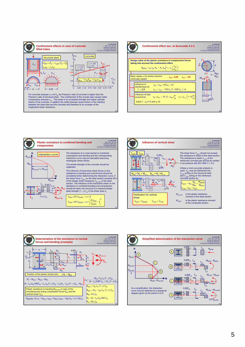
5
25
G. HanswilleUniv.-Prof. Dr.-Ing.
Institute for Steel and Composite Structures
University of Wuppertal-Germany
Confinement effects in case of concrete filled tubes
σc,r
σc,r
σaϕσaϕ
dt
concretestructural steel
ηa fyd
ydaRd,a
2yd
2,aRd,a
2,a
2Rd,a
f
f
η=σ
=σσ−σ+σ ϕϕ
0.05 0.10 0.15 0.20 0.25 0.30 0.35
fck,c
ck
r,c
fσ
ck
c,ck
ff
2.0
1.5
1.0
0.5
0
1.25
0d-2t
σc,r
For concrete stresses σc>o,8 fck the Poisson‘s ratio of concrete is higher than the Poisson‘s ratio of structural steel. The confinement of the circular tube causes radial compressive stresses σc,r. This leads to an increased strength and higher ultimate strains of the concrete. In addition the radial stresses cause friction in the interface between the steel tube and the concrete and therefore to an increase of the longitudinal shear resistance.
rcckcck ff ,21, σα+α=
α1=1,125α2= 2,5α1=1,00
α2= 5,0
26
G. HanswilleUniv.-Prof. Dr.-Ing.
Institute for Steel and Composite Structures
University of Wuppertal-Germany
Confinement effect acc. to Eurocode 4-1-1
( ) 092,015,18
0,15,0
KKco,c
Kao,a
≥λ−λ−η=η
≤λ+η=η
λ
λinfluence of slenderness for
influence of load eccentricity : ⎟
⎠⎞
⎜⎝⎛ −η=ηη−+η=η λλ d
e101de)1(10 ,ccao,aa
EdEd
NMe =
5,0≤λ
⎟⎟⎠
⎞⎜⎜⎝
⎛η++η=
ck
ykccdcaydaRd,pl f
fdt1fAAfN
Design value of the plastic resistance to compressive forces taking into account the confinement effect:
9,425,0 coao =η=ηBasic values η for stocky columns centrically loaded:
d
t
y
z
MEd NEd
fc
fye/d>0,1 : ηa=1,0 and ηc=0
27
G. HanswilleUniv.-Prof. Dr.-Ing.
Institute for Steel and Composite Structures
University of Wuppertal-Germany
Plastic resistance to combined bending and compression
NNpl,Rd
NEd
Mpl,Rd
Mpl,N,Rd= μ Mpl,Rd
fyd
(1-ρ) fyd
0,85 fcd fsd
Mpl,N Rd
NEd
VEd
2
Rd,pla
Ed,aRd,plaEd,a
Rd,plaEd,a
1V
V2V5,0V
0V5,0V
⎥⎥⎦
⎤
⎢⎢⎣
⎡−=ρ⇒>
=ρ⇒≤
zply
z
M
--
+
The resistance of a cross-section to combined compression and bending and the corresponding interaction curve may be calculated assuming rectangular stress blocks.
The tensile strength of the concrete should be neglected.
The influence of transverse shear forces on the resistance to bending and normal force should be considered when determining the interaction curve, if the shear force Va,Ed on the steel section exceeds 50% of the design shear resistance Vpl,a,Rd of the steel section. The influence of the transverse shear on the resistance in combined bending and compression should be taken into account by a reduced design steel strength (1 - ρ) fyd in the shear area Av.
interaction curve
28
G. HanswilleUniv.-Prof. Dr.-Ing.
Institute for Steel and Composite Structures
University of Wuppertal-Germany
MRd
fyd
fsd
0,85fcdfyd
+
zpl
Vc,EdVa,Ed
Nc+s
Na
Ma Mc,+s
+
-
fyd
-
-
NEd
VEdfsd
fsd
fsd -
Rd,cEd,cRd,plaEd,a VVVV ≤≤
Ed,aEdEd,c
Rd,pl
Rd,pla
Rd
aEdEd,a
VVVMM
MMVV
−=
≈=
Verification for vertical shear:
-
MRd= Ma + Mc+s NEd = Na +Nc+s
zpl
Influence of vertical shear
The shear force Va,Ed should not exceed the resistance to shear of the steel section. The resistance to shear Vc,Ed of the reinforced concrete part should be verified in accordance with EN 1992-1-1, 6.2.
Unless a more accurate analysis is used, VEd may be distributed into Va,Ed acting on the structural steel and Vc,Ed acting on the reinforced concrete section by :
Mpl,a,Rd is the plastic resistance moment of the steel section.
Mpl,Rd is the plastic resistance moment of the composite section.
29
G. HanswilleUniv.-Prof. Dr.-Ing.
Institute for Steel and Composite Structures
University of Wuppertal-Germany
Determination of the resistance to normal forces and bending (example)
tf
yzpl
zc
Nc
0,85fcd
-
fyd
zs
zs
Naf
Naf
Naw,c
zaw,c
zaw,t
Naw,t(1-ρ) fyd
VEd
NEd
Mpl,N,Rd
Position of the plastic neutral axis: Edi NN∑ =
Edydplwwydplwcdplw Nf)1()zh(tf)1(ztf85,0z)tb( =ρ−−−ρ−+−
fsd
b
hw
ydwcdw
ydwwEdpl f)1(t2f85,0)tb(
f)1(thNz
ρ−+−
ρ−+=
Plastic resistance to bending Mpl,N,Rd in case of the simultaneously acting compression force NEd and the vertical shear VEd:
szsN2)ftwh(afNt,awzt,awNc,awzc,awNczcNRd,N,plM +++++=
sdss
cdplwc
ydfaf
ydwplwt,aw
ydwplc,aw
fA2N
f85,0z)tb(N
ftbN
f)1(t)zh(N
f)1(tzN
=
−=
=
ρ−−=
ρ−=
Ns
Ns
tw-
+
Edt,awc,awc NNNN =−+
As
30
G. HanswilleUniv.-Prof. Dr.-Ing.
Institute for Steel and Composite Structures
University of Wuppertal-Germany
Simplified determination of the interaction curve
N
M
2N Rd,pm
Rd,pmN
Rd,plM Rdmax,M
Rd,plNA
B
D
C
Rd,plN
Rd,plRd,B MM =
Rd,pmN
Rd,pmN5,0
A
B
C
D
0,85fcd fsd
fsd
fsd
fsd
- -
-+
+
+
zpl 2hn
hn
-
--
-
-
-
+
-
Rd,plRd,C MM =
Rdmax,Rd,D MM =
fyd
fyd
fyd
fyd
fyd
fydfyd
zpl
zpl
As a simplification, the interaction curve may be replaced by a polygonal diagram given by the points A to D.
0,85fcd
0,85fcd
0,85fcd

6
31
G. HanswilleUniv.-Prof. Dr.-Ing.
Institute for Steel and Composite Structures
University of Wuppertal-Germany
Resistance at points A and D
fcdfsd
- --
0M
NNNN
Rd,A
Rd,plsRd,plcRd,plaRd,pl
=
++=
fyd
Point A
Mpla,RdMpls,Rd0,5 Mplc,Rd
0,85 fcdfsd
fyd-+
-
+
zsi
zsi
bc
hc
h
Rdmax,Rd,D
Rd,plcRd,D
MM
N5,0N
=
=
[ ] yssisisds,plRd,pls fzAfWM ∑==
cds,pla,pl
2cc
cdc,plRd,plc f85,0WW4
hbf85,0WM
⎥⎥
⎦
⎤
⎢⎢
⎣
⎡−−==
Point D
Nplc,Rd Npls,Rd Npla,Rd
ydffw
2f
yda,plRd,pla f)th(tb4
t)t2h(fWM⎥⎥⎦
⎤
⎢⎢⎣
⎡−+
−==
b
h
tftw
Rd,plcRd,plsRd,plaRdmax, M21MMM ++=
Wpl,a plastic section modulus of the structural steel section
Wpl,s plastic section modulus of the cross-section of reinforcement
Wpl,c plastic section modulus of the concrete section 32
G. HanswilleUniv.-Prof. Dr.-Ing.
Institute for Steel and Composite Structures
University of Wuppertal-Germany
Bending resistance at Point B (Mpl,Rd )
Mpl,Rd
Mpln,Rd
0,85fcd
fsd
fyd
-+
-
+ 2fyd
+
+
2 fsd
-
+
0,85fcd 0,85fcd
- -
fyd
hn
fsd
MD,Rd
ND,Rdzpl
+ =
+
+
+
+
ND,Rd
hn
hn
hn
+ =
At point B is no resistance to compression forces. Therefore the resistance to compression forces at point D results from the additional cross-section zones in compression. With ND,Rd the depth hn and the position of the plastic neutral axis at point B can be determined. With the plastic bending moment Mn,Rd resulting from the stress blocks within the depth hn the plastic resistance moment Mpl,Rd at point B can be calculated by:
Rdln,pRd,DRd,pl MMM −=
+
+
zpl
hn
Point D
Point B
33
G. HanswilleUniv.-Prof. Dr.-Ing.
Institute for Steel and Composite Structures
University of Wuppertal-Germany
The bending resistance at point C is the same as the bending resistance at point B.
MC,Rd= Mpl,Rd
The normal force results from the stress blocks in the zone 2hn.
Plastic resistance moment at Point C
Mpl,Rd
0,85 fcd
fsd
fyd
-
+
-
+
2fyd
-
-
2 fsd
-
+
0,85fcd 0,85fcd
- -
fyd
2hn fsd+ =
+
+ +
+
+
NC,Rd
2hn
2hn
2hn
+ =
+
Nc,Rd
Mc,Rd2hn
NC,Rd = 2 ND,Rd = Ncpl,Rd = Npm,Rd
hn
zpl
Point B Point C
34
G. HanswilleUniv.-Prof. Dr.-Ing.
Institute for Steel and Composite Structures
University of Wuppertal-Germany
Determination of Mn,Rd
hn
hn2hn
0,85 fcd2 fsd 2 fyd
---
-fsd fyd
-+
Mn,Rd
ND,Rd= Npm,Rd
hn
( )2
hth)f2(zA2)f2(zf)A2(2
hf85,0h)tb(M nwnydsssdscds
ncdnwRd,n ++⎥⎦
⎤⎢⎣⎡ −−=
( )2h2thfz2fA2zf)A2(
2hf85,0h)tb(M n
wnydssdsscdsn
cdnwRd,n ++⎥⎦⎤
⎢⎣⎡ −−=
A
B Mn,Rd
cdplccn,pl f85,0W21M = sds,plsn,pl fWM = yda,plan,pl fWM == + +
The stress blocks acc. to A and B give the same bending moment Mn,Rd
The depth hn results from the equilibrium condition ∑Ni= Npm,Rd
Rd,pm
ydnw
scdsd
cdnwN
f2)ht()A2()ff2(
f85,0h)tb(=
⎪⎭
⎪⎬
⎫
+−+
−
Wpl,c, Wpl,s und Wpl,a are the plastic section moduliof the cross-section within the depth 2hn.
Rd,nM
0,85 fcd
35
G. HanswilleUniv.-Prof. Dr.-Ing.
Institute for Steel and Composite Structures
University of Wuppertal-Germany
cdcRd,pm f85,0AN =
sds,plcdc,plyda,plRdmax, fWf85,0W21fWM ++=
zin
1snisn,pl eAW ∑=
=i
sdsn,plcdcn,plydan,plRd,n fWf85,0W21fWM ++=
Rd,nRdmax,Rd,pl MMM −=
d
ey
ez
y
z
b
2nan,pl ht2W =
t rari
s,pla2i
3i
2c,pl W)r
2d)(4(rr
32
4)t2d()t2b(W −−π−−−
−−=
s,plc,pla2a
3a
2a,pl WW)r
2d)(4(
32
4W −−−π−−−= rrdb
ziss,pl eAn
1iW i=
Σ=
)ff2(t4fb2)ff2(AN
hcdydcd
cdsdsnRd,pmn −+
−−=
sn,pl2ncn,pl Wh)t2b(W −−=
Depth hn and plastic section moduliwithin the depth hn:
Plastic section moduli of the composite section:
Determination of hn and Mpl,Rd for concrete filled rectangular hollow sections
36
G. HanswilleUniv.-Prof. Dr.-Ing.
Institute for Steel and Composite Structures
University of Wuppertal-Germany
zin
1snisn,pl eAW ∑=
=i
d
ey
ez
y
z
t
s,pl3
c,pl W6
)t2d(W −−
=
s,plc,pl3
a,pl WW6dW −−=
)ff2(t4fd2)ff2(AN
hcdydcdcdsdsnRd,pm
n −+
−−=
2nan,pl ht2W =
zisis,pl eAn
1iW
=Σ=
zin
1snisn,pl eAW ∑=
=i
Plastic section moduli of the composite section:
Determination of hn and Mpl,Rd for concrete filled circular hollow sections
Depth hn and plastic section moduliwithin the depth hn:
cdcRd,pm f85,0AN =
sds,plcdc,plyda,plRdmax, fWf85,0W21fWM ++=
sdsn,plcdcn,plydan,plRd,n fWf85,0W21fWM ++=
Rd,nRdmax,Rd,pl MMM −=

7
37
G. HanswilleUniv.-Prof. Dr.-Ing.
Institute for Steel and Composite Structures
University of Wuppertal-Germany
)(4
)2(W ffw
2f
a,pl thtbtth−+
−=
bc
hc
b
h
ey
ez
y
z
s,pla,pl
2cc
c,pl WW4
W −−=hb
zisis,pl eAn
1iW
=Σ=
Plastic neutral axis outside the steel section: h/2 ≤ hn < hc/2
cdc
cdsdsncdydaRd,pmn f85,0b2
)f85,0f2(A)f85,0f2(ANh
−−−−= a,plan,pl WW =
Plastic neutral axis in the flange of the steel section: h/2-tf < hn < h/2
)f85,0f2(b2f85,0b2)f85,0f2(A)f85,0f2()hbA(N
hcdydcdc
cdsdsncdydaRd,pmn −+
−−−−−= )h4h(
4bWW 2
n2
a,plan,pl −−=
Plastic neutral axis in the web of the steel section: 2 hn ≤ h/2-tf
)f85,0f2(t2f85,0b2)f85,0f2(AN
hcdydwcdc
cdsdsnRd,pmn −+
−−= 2
nwan,pl htW =
sn,plan,pl2nccn,pl WWhbW −−=
zin
1snisn,pl eAW ∑=
=i
twtf
Determination of hn and Mpl,Rd for concrete encased sections – strong axis
cdcRd,pm f85,0AN =
sds,plcdc,plyda,plRdmax, fWf85,0W21fWM ++=
sdsn,plcdcn,plydan,plRd,n fWf85,0W21fWM ++=
Rd,nRdmax,Rd,pl MMM −=
38
G. HanswilleUniv.-Prof. Dr.-Ing.
Institute for Steel and Composite Structures
University of Wuppertal-Germany
yisis,pl eAn
1iW
=Σ=
plastic neutral axis outside the steel section b/2 ≤ hn < bc/2
a,plan,pl WW =
plastic neutral axis in the web of the steel section : 2 hn ≤ tw/2
Plastic neutral axis in the flange of the steel section : tw/2 < hn < b/2
sn,plan,pl2nccn,pl WWhhW −−=
yin
1snisn,pl eAW ∑=
=i
24)2(W
2f
2wf
a,plbttth
+−
=
s,pla,pl2
ccc,pl WW
4W −−=
bh
cdc
cdsdsncdydaRd,pmn f85,0h2
)f85,0f2(A)f85,0f2(ANh
−−−−=
)f85,0f2(t4f85,0h2)f85,0f2(A)f85,0f2)(ht2A(N
hcdydfcdc
cdsdsncdydfaRd,pmn −+
−−−−−=
)h4b(2tWW 2
n2f
a,plan,pl −−=
)f85,0f2(h2f85,0h2)f85,0f2(AN
hcdydcdc
cdsdsnRd,pmn −+
−−= 2
nan,pl hhW =
bc
hc
b
h
ey
ez y
ztw tf
Determination of hn and Mpl,Rd for concrete encased sections – weak axis
cdcRd,pm f85,0AN =
sds,plcdc,plyda,plRdmax, fWf85,0W21fWM ++=
sdsn,plcdcn,plydan,plRd,n fWf85,0W21fWM ++=
Rd,nRdmax,Rd,pl MMM −=
39
G. HanswilleUniv.-Prof. Dr.-Ing.
Institute for Steel and Composite Structures
University of Wuppertal-Germany
Part 4:
Simplified design method
40
G. HanswilleUniv.-Prof. Dr.-Ing.
Institute for Steel and Composite Structures
University of Wuppertal-Germany
Methods of verification acc. to the simplified method
Design based on the European buckling curves
Design based on second order analysis with equivalent geometrical bow imperfections
Kλ
κ
wo
wo
Axial compression
Resistance of member in combined compression and bending
Simplified Method
Design based on second order analysis with equivalent geometrical bow imperfections
41
G. HanswilleUniv.-Prof. Dr.-Ing.
Institute for Steel and Composite Structures
University of Wuppertal-GermanyScope of the simplified method
double symmetrical cross-sectionuniform cross-sections over the member length with rolled, cold-formed or welded steel sectionssteel contribution ratio
relative slenderness
longitudinal reinforcement ratio
the ratio of the depth to the width of the composite cross-section should be within the limits 0,2 and 5,0
Rd,pl
yda
NfA
9,02,0 =δ≤δ≤
0,2N
N
cr
Rk,pl ≤=λ
c
sss A
A%0,6%3,0 =ρ≤ρ≤
42
G. HanswilleUniv.-Prof. Dr.-Ing.
Institute for Steel and Composite Structures
University of Wuppertal-Germany
LoadF [kN]
deflection w [mm]
2000
1500
1000
500
020 40 60 80 100
short term testFu = 2022 kN
Fu = 1697 kN
long term test
Fv = 534 kN
30 cm
30 c
m
e=3 cm
L =
800
cm
e
F The horizontal deflection and the second order bending moments increase under permanent loads due to creep of concrete. This leads to a reduction of the ultimate load.
wo
permanent load
The effects of creep of concrete are taken into account in design by a reduced flexural stiffness of the composite cross-section.
wt
Effects of creep of concrete

8
43
G. HanswilleUniv.-Prof. Dr.-Ing.
Institute for Steel and Composite Structures
University of Wuppertal-Germany
Effects of creep on the flexural stiffness
The effects of creep of concrete are taken into account by an effective modulus of elasticity of concrete
)t,t(N
N1
EE
oEd
Ed,G
cmeff,c
ϕ+
=
Ecm Secant modulus of concrete
NEd total design normal force
NG,Ed part of the total normal force that is permanent
ϕ(t,to) creep coefficient as a function of the time at loading to, the time t considered and the notional size of the cross-section
b b
h h
UA2h c
o =
)hb(2U += b5,0h2U +≈
notional size of the cross-section for the determination of the creep coefficient ϕ(t,to)
In case of concrete filled hollow section the drying of the concrete is significantly reduced by the steel section. A good estimation of the creep coefficient can be achieved, if 25% of that creep coefficient is used, which results from a cross-section, where the notional size hois determined neglecting the steel hollow section.
ϕt,eff = 0,25 ϕ(t,to)
effective perimeter U of the cross-section
44
G. HanswilleUniv.-Prof. Dr.-Ing.
Institute for Steel and Composite Structures
University of Wuppertal-Germany
b
b
b
a
c
b
buckling curve
cross-section
%3s ≤ρ
%6%3 s ≤ρ<
cr
k,plNN
=λ
Rd,pl
RdNN
=χ
0,2 1,0
1,0
0,8
0,6
0,4
0,2
0,6 1,4
a
b
c
0,1NN
Rd
Ed ≤
Rd,plRd NN χ=
cdcsdsydaRd,pl fAfAfAN ν++=
Verification:
Design value of resistance
0,2N
N
cr
Rk,pl ≤=λ
1,8
Verification for axial compression with the European buckling curves
buckling about strong axis
buckling about weak axis
85,0=ν
00,1=ν
85,0=ν
85,0=ν
00,1=ν
00,1=ν
45
G. HanswilleUniv.-Prof. Dr.-Ing.
Institute for Steel and Composite Structures
University of Wuppertal-Germany
relative slenderness
relative slenderness:
0,2N
N
cr
Rk,pl ≤=λ
sksckcykaRk,pl fAfAfAN +ν+=
2eff
2
cr )L()EJ(N
βπ
=
)JEJEKJE()EJ( ssceff,ceaaeff ++=
elastic critical normal force
85,0
ffc
ckcd
=ν
γ=
effective flexural stiffness
00,1
ffc
ckcd
=ν
γ=
Ke=0,6
characteristic value of the plastic resistance to compressive forces
β - buckling length factor
46
G. HanswilleUniv.-Prof. Dr.-Ing.
Institute for Steel and Composite Structures
University of Wuppertal-Germany
22II,eff
2
cr
cr
EdoEdEd
L)JE(
N
NN1
1wNMmax
β
π=
−=
bending moments taking into account second order effects:
9,0K5,0Kwith
)JEJEKJE(K)EI(
oII,e
ssceff,ceaaoII,eff
==
++=
Verification
αM= 0,9 for S235 and S355
αM= 0,8 for S420 and S460
Rd,plMRdEd MMMmax μα=≤
Effective flexural stiffness
Npl,Rd
NEd
N
wo
Mpl,RdMRd
αM μ Mpl,Rd
MMpl,N,Rd
fsd
Mpl,N RdNEd
VEd
fyd
(1-ρ) fyd
0,85fcd
-
+
-
Verification for combined compression and bending
wo equivalent geometrical bow imperfection
The factor αM takes into account the difference between the full plastic and the elasto-plastic resistance of the cross-section resulting from strain limitations for concrete.
47
G. HanswilleUniv.-Prof. Dr.-Ing.
Institute for Steel and Composite Structures
University of Wuppertal-Germany
Favourable effects of the compression force on the bending resistance of the cross-section
Rd,plNM
=μ
1,0
Npl,Rd
0,1=μ
max,dμ
Case A Case B
MEd,max MEd,max
Case A: Bending moment depends directly on the action of the normal force
Case B: Bending moment and normal force result from independent actions.
NEd,A NEd,B
MEd,R
MEd,R=NEd e
A,dμ
B,dμ
max,dμ
N
NEd,A
NEd,B
0,5 Npm,Rd
Values μd greater than 1,0 should only be used where the bending moment MEd depends directly on the action of the normal force NEd, for example where the moment MEd results from an eccentricity of the normal force NEd. Otherwise an additional verification is necessary, because an overestimation of the normal force leads to an increased bending resistance (see normal forces NEd,A and NEd,B). For composite compression members subjected to bending moments and normal forces resulting from independent actions, the partial factor γF for those internal forces that lead to an increase of resistance should be reduced by 20%.
48
G. HanswilleUniv.-Prof. Dr.-Ing.
Institute for Steel and Composite Structures
University of Wuppertal-Germany
Global analysis
First-order analysis may be used if the increase of the relevant internal forces or moments caused by the deformations given by first-order analysis is less than 10%. This condition may be assumed to be fulfilled if the following criterion is satisfied:
αcr ≥ 10
where αcr is the factor by which the design loading would have to be increased to cause elastic instability.
Appropriate allowances shall be incorporated in the structural analysis to cover the effects of imperfections, including residual stresses and geometrical imperfections such as lack of verticality, lack of straightness, and unavoidable minor eccentricities in joints of the unloaded structures.
The assumed shape of imperfections shall take account of the elastic buckling mode of the structure or member in the plane of buckling considered, in the most unfavourable direction and form.

9
49
G. HanswilleUniv.-Prof. Dr.-Ing.
Institute for Steel and Composite Structures
University of Wuppertal-Germany
Equivalent initial bow imperfections
Buckling curve
a b c
wo= L/300 wo= L/200 wo= L/150
%3s ≤ρ
%6%3 s ≤ρ<
Member imperfection
50
G. HanswilleUniv.-Prof. Dr.-Ing.
Institute for Steel and Composite Structures
University of Wuppertal-Germany
Imperfections for global analysis of frames
hmo ααφ=φ
Global initial sway imperfection acc. to EN 1993-1-1:
φ φ Φo basic value with Φo = 1/200
αh reduction factor for the height h in [m]
αm reduction factor for the number of columns in a row
0,132but
h2
hh ≤α≤=α
⎥⎦⎤
⎢⎣⎡ +=α
m115,0m
m is the number of columns in a row including only those columns which carry a vertical load NEd not less than 50% of the average value of the column in a vertical plane considered.
h
sway imperfection
equivalent forces
NEd,1 NEd,2
Φ NEd,1 NEd,1NEd,2
Φ NEd,1
Φ NEd,2
Φ NEd,2
51
G. HanswilleUniv.-Prof. Dr.-Ing.
Institute for Steel and Composite Structures
University of Wuppertal-Germany
Frames sensitive against second order effects
1,Ed
Rk,plNN
5,0≤λw0
φ2
φ1
NEd,1 NEd,2
equivalent forces
NEd,1 φ1
2,Ed22
o NLw8q=
2,Ed2
o NLw4
2,Ed2
o NLw4
L2
L1 2,Ed
Rk,plNN
5,0>λ
NEd,1NEd,2
NEd,1 φ1
NEd,2 φ2
NEd,2 φ2
i,Ed
Rk,plNN
5,0≤λ
2i
eff2
cr L)EJ(N π
=
)JEJE6,0JE()EJ( ssceff,caaeff ++=
Within a global analysis, member imperfections in composite compression members may be neglected where first-order analysis may be used. Where second-order analysis should be used, member imperfections may be neglected within the global analysis if:
cr
Rk,plN
N=λ
imperfections
52
G. HanswilleUniv.-Prof. Dr.-Ing.
Institute for Steel and Composite Structures
University of Wuppertal-Germany
Second order analysis
⎟⎠
⎞⎜⎝
⎛−
εξ−ε
+⎟⎠
⎞⎜⎝
⎛ε
ξε+ξ−ε=ξ 1
)2/(cos)5,0(cosM
sinsin)1(sinrM)(M oR
⎟⎠
⎞⎜⎝
⎛−
εξ−ε
+⎟⎠
⎞⎜⎝
⎛ε
ξε+ξ−εε=ξ 1
)2/(cos)5,0(sinM
sincos)1(cosr
LM)(V o
Rz
Bending moments including second order effects:
Maximum bending moment at the point ξM:
[ ] 0
2
omax M)5,0cos(
c1M)r1(M5,0M −ε
+++=
)5,0(tan1
M2)r1(M)1r(Mc
o ε++−
=ε
+=ξcarctan5,0M
2o2
o1)wN8Lq(Mε
+=II,eff
Ed)JE(
NL=ε
⎟⎠
⎞⎜⎝
⎛ =ξ
0ddM
maxM
ζM
ζ
Lwoq
MR
r MRN
EJ
MR
r MR
53
G. HanswilleUniv.-Prof. Dr.-Ing.
Institute for Steel and Composite Structures
University of Wuppertal-Germany
Simplified calculation of second order effects
4,0
3,0
2,0
1,0
0,25 0,50 0,75 1,00
exact Solution
simplified solution
r=1,0
r=0,5
r= - 0,5
r=0
k
crNN
MR
r MR N
L
EJ
ζM
Exact solution:
)5,0cos(c1)r1(M5,0M
2
Rmax ε+
+=
)5,0(tan1
r11rc
ε+−
=
ε+=ξ
carctan5,0MII,eff
Ed)JE(
NL=ε
simplified solution:
cr
EdR
max
NN1M
Mk−
β== r44,066,0 +=β
maxM
ζ
44,0≥β
MR
r MR
54
G. HanswilleUniv.-Prof. Dr.-Ing.
Institute for Steel and Composite Structures
University of Wuppertal-Germany
N
NRd wo
Mpl,RdMRd
μ Mpl,Rd
NEd=NRd
⎥⎦
⎤⎢⎣
⎡ −ε
= 1)2/cos(
1L
)EJ(w8M 2
II,effo
Bending moment based on second order analysis:
II,eff
Rd)EJ(
NL=ε
Resistance to axial compression based on the European buckling curves:
Rd,plRd NN χ=
Determination of the equivalent bow imperfection:
Rd,plMRd MM μα=M
⎥⎦
⎤⎢⎣
⎡−
ε−
μα=
1)2/(cos1
1)EJ(8
LMw
II,eff
2Rd,pldM
o
Background of the member imperfections
The initial bow imperfections were recalculated from the resistance to compression calculated with the European buckling curves.
Bending resistance:
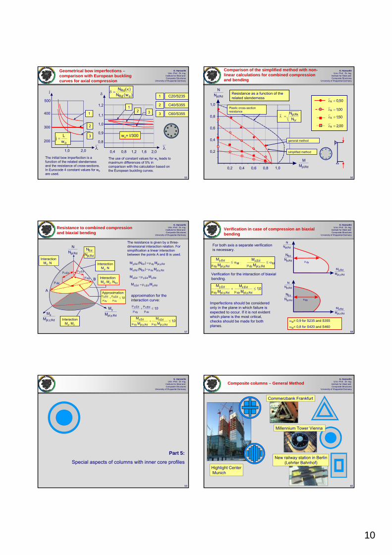
10
55
G. HanswilleUniv.-Prof. Dr.-Ing.
Institute for Steel and Composite Structures
University of Wuppertal-Germany
500
400
300
200
j
λ1,0 2,0
C20/S235
C40/S355
C60/S355
owLj =
λ
1
2
3
0,4 0,8 1,2 1,6 2,0
1,0
1,1
1,2
0,9
0,8
1
12
2
3
3
δ )w(N)(NoRd
Rd κ=δ
Geometrical bow imperfections –comparison with European buckling curves for axial compression
The initial bow imperfection is a function of the related slenderness and the resistance of cross-sections. In Eurocode 4 constant values for w0are used.
wo= l/300
The use of constant values for wo leads to maximum differences of 5% in comparison with the calculation based on the European buckling curves.
56
G. HanswilleUniv.-Prof. Dr.-Ing.
Institute for Steel and Composite Structures
University of Wuppertal-Germany
Rd,plNN
Rd,plMM
0,2 0,4 0,6 0,8 1,0
0,2
0,4
0,6
0,8
1,050,0k =λ
00,1k =λ
50,1k =λ
00,2k =λ
Resistance as a function of the related slenderness
general method
simplified method
cr
Rk,plN
N=λ
Plastic cross-section resistance
Comparison of the simplified method with non-linear calculations for combined compression and bending
57
G. HanswilleUniv.-Prof. Dr.-Ing.
Institute for Steel and Composite Structures
University of Wuppertal-Germany
Resistance to combined compression and biaxial bending
InteractionMy, Mz, NEd
Interaction Mz, N Interaction
My, N
InteractionMy, Mz
Rd,y,pl
y
MM
Rd,z,pl
zM
M
Rd,plNN
The resistance is given by a three-dimensional interaction relation. For simplification a linear interaction between the points A and B is used.
Approximation:A
Bdyμ
dzμ
Rd,pl
EdNN
Rd,y,pldyEdRd,y M)N(M μ=
Rd,y,pldzEdRd,z M)N(M μ=Ed,zμ Ed,yμ
Rd,yEd,yEd,y MM μ=
Rd,yEd,zEd,z MM μ=
approximation for the interaction curve:
0,1dz
Ed,z
dy
Ed,y ≤μ
μ+
μ
μ
0,1M
MM
M
Rd,z,pldz
Ed,z
Rd,y,pldy
Ed,y ≤μ
+μ
0,1dz
Ed,z
dy
Ed,y ≤μ
μ+
μ
μ
58
G. HanswilleUniv.-Prof. Dr.-Ing.
Institute for Steel and Composite Structures
University of Wuppertal-Germany
Verification in case of compression an biaxial bending
MRd,y,pldz
Ed,zM
Rd,y,pldy
Ed,yM
MM
Mα≤
μα≤
μ
0,1M
MM
M
Rd,y,pldz
Ed,z
Rd,y,pldy
Ed,y ≤μ
+μ
Rd,plNN
Rd,y,pl
Rd,yMM
dyμ
Rd,plNN
Rd,z,pl
Rd,zMM
dzμ
For both axis a separate verification is necessary.
Verification for the interaction of biaxial bending.
Imperfections should be considered only in the plane in which failure is expected to occur. If it is not evident which plane is the most critical, checks should be made for both planes.
Rd,pl
EdNN
Rd,pl
EdNN
αM= 0,9 for S235 and S355
αM= 0,8 for S420 and S460
59
G. HanswilleUniv.-Prof. Dr.-Ing.
Institute for Steel and Composite Structures
University of Wuppertal-Germany
Part 5:
Special aspects of columns with inner core profiles
60
G. HanswilleUniv.-Prof. Dr.-Ing.
Institute for Steel and Composite Structures
University of Wuppertal-Germany
Composite columns – General Method
Commerzbank Frankfurt
Highlight CenterMunich
New railway station in Berlin (Lehrter Bahnhof)
Millennium Tower Vienna

11
61
G. HanswilleUniv.-Prof. Dr.-Ing.
Institute for Steel and Composite Structures
University of Wuppertal-Germany
Composite columns with concrete filled tubes and steel cores – special effects
Resistance based on stress blocks (plastic resistance)
Non linear resistance with strain limitation for concrete
tube core concretefy fy fc
fy fy fc
N
M
M
N
strains ε
Rd,pl
RdM M
Mμ
=α
Cross-sections with massive inner cores have a very high plastic shape factor and the cores can have very high residual stresses. Therefore these columns can not be design with the simplified method according to EN 1944-1-1.
σED
r62
G. HanswilleUniv.-Prof. Dr.-Ing.
Institute for Steel and Composite Structures
University of Wuppertal-Germany
distribution of yield strenghtσED [N/mm2]
U/A [1/m]
dK [mm]10 20 30 40 50
80100200400 130
50
100
150
200
250
300
⎥⎥⎦
⎤
⎢⎢⎣
⎡−σ=σ 2
K
2EDE
rr21)r(
fyk fy(r)
2
kyk
y
rr1,095,0
f)r(f
⎟⎟⎠
⎞⎜⎜⎝
⎛+=
fyk – characteristic value of the yield strenght
σED
r, rk
residual stresses:
rk
dk
kdU π=
4/dA 2kπ=
Residual stresses and distribution of the yield strength
ddK
63
G. HanswilleUniv.-Prof. Dr.-Ing.
Institute for Steel and Composite Structures
University of Wuppertal-Germany
General method – Finite Element Model
initial bow imperfectionstresses in the tube
stresses in concrete
load introduction
cross-section
64
G. HanswilleUniv.-Prof. Dr.-Ing.
Institute for Steel and Composite Structures
University of Wuppertal-Germany
dK
σE=fy
tube 406x6,3 - S235
concrete C30core dK=300 mm fy=265 N/mm2
buckling curve d(considering residual stresses)
χ
1,0
0,5
0,5 1,0 1,5Kλ
NRd= χ Npl,Rd
buckling curve a(no residual stresses)
Influence of residual stresses - comparison of resistance with the European buckling curves
65
G. HanswilleUniv.-Prof. Dr.-Ing.
Institute for Steel and Composite Structures
University of Wuppertal-Germany
Part 6:
Load introduction and longitudinal shear
66
G. HanswilleUniv.-Prof. Dr.-Ing.
Institute for Steel and Composite Structures
University of Wuppertal-Germany
Load introduction and shear connection
Provision shall be made in regions of load introduction for internal forces and moments applied from members connected to the ends and for loads applied within the length to be distributed between the steel and concrete components, considering the shear resistance at the interface between steel and concrete. A clearly defined load path shall beprovided that does not involve an amount of slip at this interface that would invalidate the assumptions made in design.
Where composite columns and compression members are subjected tosignificant transverse shear, as for example by local transverse loads and by end moments, provision shall be made for the transfer of the corresponding longitudinal shear stress at the interface between steel and concrete. For axially loaded columns and compression members, longitudinal shear outside the areas of load introduction need not to be considered
Basic requirements

12
67
G. HanswilleUniv.-Prof. Dr.-Ing.
Institute for Steel and Composite Structures
University of Wuppertal-Germany
Load introduction over the steel section
NEd
Nc,Ed
Na,Ed
LE < 2,0 d
d
Aa As
Ac
PD
load introduction by headed studs within the load introduction length LE
⎩⎨⎧
≤3/Ld2
LE
d minimum transverse dimension of the cross-section
L member length of the column
sectional forces of the cross-section :
Rd,pl
c,plEdEd,c
Rd,pl
s,plEdEd,s
Rd,pl
a,plEdEd,a N
NNN
NN
NNNN
NN ===
required number of studs n resulting from the sectional forces NEd,c+ NEd,s:
Ns,Ed
⎥⎥⎦
⎤
⎢⎢⎣
⎡−=+=
Rd,pl
a,plEdEd,sEd,cEd,L N
N1NNNV RdRd,L PnV =
PRd – design resistance of studs68
G. HanswilleUniv.-Prof. Dr.-Ing.
Institute for Steel and Composite Structures
University of Wuppertal-Germany
Load introduction for combined comression and bending
NEdMEd
Ma,EdNa,Ed
Mc,Ed +Ms,Ed
Nc,Ed +Ns,Ed
Rd,pl
EdNN
sectional forces due to NEdund MEd
sectional forces based on plastic theory
Rd,scRd,aRdRd,scRd,aRd NNNMMM ++ +=+=
2
Rd,pl
Ed2
Rd,pl
Edd N
NMMR ⎟
⎟⎠
⎞⎜⎜⎝
⎛+⎟
⎟⎠
⎞⎜⎜⎝
⎛=
2
Rd,pl
Rd2
Rd,pl
Rdd N
NMME ⎟
⎟⎠
⎞⎜⎜⎝
⎛+⎟
⎟⎠
⎞⎜⎜⎝
⎛=
Rd,sc
Ed,sc
Rd,sc
Ed,sc
Rd,a
Ed,a
Rd,a
Ed,a
dd
MM
NN
MM
NN
RE
+
+
+
+ ====
Rd,plNN
Rd,pl
RdNN
Rd,pl
EdMM
Rd,pl
RdMM
Rd,plMM
1,0
1,0
dE
dR
fyd
zpl
Nc+s,RdNa,Rd
Ma;Rd Mc,+s,Rd
+
--
fsd
fsd0,85fcd MRd
NRd
+ =
69
G. HanswilleUniv.-Prof. Dr.-Ing.
Institute for Steel and Composite Structures
University of Wuppertal-Germany
Load introduction – Example
fyd
zpl
-Nc+s,RdNa,Rd
Ma;Rd Mc,+s,Rd
+
- -
fsd
fsdfcd
Zs
zc Zs
shear forces of studs based on elastic theory shear forces of studs based on plastic theory
Nc+s,EdNc+s,Ed Mc+s,Ed
-Ns,i
Ns,i
-Nc∑+=
∑+=
+
+
sisiccRd,sc
sicRd,sc
zNzNM
NNN
PEd(N)
PEd(M)
ri ehPed,v
Ped,h
n5,0eM
nN
Pmaxh
Ed,scEd,scEd
++ +=
xizi
2
i2i
Ed,sc2
i2i
Ed,scEd,scEd z
r
Mx
r
Mn
NPmax
⎥⎥⎦
⎤
⎢⎢⎣
⎡
∑+
⎥⎥⎦
⎤
⎢⎢⎣
⎡
∑+= +++
n – number of studs within the load introduction length
sectional forces based on stress blocks:
Mc+s,Ed
70
G. HanswilleUniv.-Prof. Dr.-Ing.
Institute for Steel and Composite Structures
University of Wuppertal-Germany
Load introduction by end plates
bcx bcy
bcx
bcy
I I
Section I-I Ac1
NEdNEd, c+sNEd,a
Aa1
Ed,aEdsEdc
Rd,pl
a,plEdEd,a
NNNNN
NN
−=
=
+
sectional forces of the steel and concrete section of the column:
sectional forces in Section I-I:
Ed,1aEdEd,1c
1a,pl1c,pl
1a,plEdEd,1a
NNN
NNN
NN
−=
⎥⎥⎦
⎤
⎢⎢⎣
⎡
+=
distribution with a ratio 1:2,5
Longitudinal shear force:
Rd,LEd,1cEd,scEd,L V)NN(V ≤−= +
1ccdc1c
cd1c1c,pl
yd1a1a,pl
Af3AAfAN
fAN
≤=
=
0,1NN
0,1NN
1c,pl
Ed,1c
1a,pl
Ed,1a ≤≤
verification in Section I-I
71
G. HanswilleUniv.-Prof. Dr.-Ing.
Institute for Steel and Composite Structures
University of Wuppertal-Germany
Shear resistance of stud connectors welded to the web of partially encased I-Sections
µ PRd / 2 µ PRd / 2
PRd
Where stud connectors are attached to the web of a fully or partially concrete encased steel I-section or a similar section, account may be taken of the frictional forces that develop from the prevention of lateral expansion of the concrete by the adjacent steel flanges. This resistance may be added to the calculated resistance of the shear connectors. The additional resistance may be assumed to be on each flange and each horizontal row of studs, where μis the relevant coefficient of friction that may be assumed. For steel sections without painting, μ may be taken as 0,5. PRd is the resistance of a single stud.
Dc
Rd,LRRdRd,L VPV +=
RdRd,LR PV μ=72
G. HanswilleUniv.-Prof. Dr.-Ing.
Institute for Steel and Composite Structures
University of Wuppertal-Germany
PRd
< 300 < 400 < 600
PRd PRdPRd PRd PRd
VLR,Rd/2
RdRd,LRRd,LRRdRd,L PVVPnV μ=+=
Shear resistance of stud connectors welded to the web of partially encased I-Sections
In absence of better information from tests, the clear distance between the flanges should not exceed the values given above.
vcmck
21,Rd
1Efd29,0Pγ
α=
v
2
u2,Rd1
4df8,0P
γ⎟⎟⎠
⎞⎜⎜⎝
⎛ π⋅=
PRd= min

13
73
G. HanswilleUniv.-Prof. Dr.-Ing.
Institute for Steel and Composite Structures
University of Wuppertal-Germany
test series S1 test series S2
F [kN]
w [mm]
FFFF
test S1/3
test S3/3
0 2 4 6 8 10 12 14 160
500
1000
1500
2000
2500
3000
3500
Shear resistance of stud connectors welded to the web of partially encased I-sections
74
G. HanswilleUniv.-Prof. Dr.-Ing.
Institute for Steel and Composite Structures
University of Wuppertal-Germany
Load introduction – longitudinal shear forces in concrete
NEd
Dc Dc
Zs Zs
ZsDc
θθ
I I
Longitudinal shear force in section I-I:
not directly connected concrete area As1
sdscdc
sd1scd1c
Rd,pl
a,plEdEd,L fAf85,0A
fAf85,0ANN
1NV++
⎥⎥⎦
⎤
⎢⎢⎣
⎡−=
NEd
bccy cy
LE
I I
As- cross-section area of the stirrups
Longitudinal shear resistance of concrete struts:
Ecdy
max,Rd,L Ltancot
f85,0c4V
θ+θ
ν=
longitudinal shear resistance of the stirrups:
θ =45o
Eydw
ss,Rd,L Lcotf
sA4V θ=
sw- spacing of stirrups
2ckck mm/Ninfwith))250/f(1(6,0 −=ν
75
G. HanswilleUniv.-Prof. Dr.-Ing.
Institute for Steel and Composite Structures
University of Wuppertal-Germany
test I/1
FF
w [mm]
F [kN]
Fu = 1608 kN
2000
1500
1000
500
00 2 4 6 8 10 12 14
Load introduction – longitudinal shear forces in concrete – test results
w
76
G. HanswilleUniv.-Prof. Dr.-Ing.
Institute for Steel and Composite Structures
University of Wuppertal-Germany
Load introduction – Examples (Airport Hannover)
Load introduction with gusset plates
77
G. HanswilleUniv.-Prof. Dr.-Ing.
Institute for Steel and Composite Structures
University of Wuppertal-Germany
Load introduction with partially loaded end plates
Load introduction with partially loaded end plates
78
G. HanswilleUniv.-Prof. Dr.-Ing.
Institute for Steel and Composite Structures
University of Wuppertal-Germany
Load introduction with distance plates for columns with inner steel cores
distance plates
Post Tower Bonn

14
79
G. HanswilleUniv.-Prof. Dr.-Ing.
Institute for Steel and Composite Structures
University of Wuppertal-Germany
Stiffener
Distance plate
σc σc σc
Composite columns with hollow sections –Load introduction
gusset plate stiffeners and end plates distance plates
80
G. HanswilleUniv.-Prof. Dr.-Ing.
Institute for Steel and Composite Structures
University of Wuppertal-Germany
σc,r
σa,tσa,y
σc
σa
The confinement by the tubes leads to a high resistance in partially loaded areas.
Confinement effects in partiallly loaded areas
81
G. HanswilleUniv.-Prof. Dr.-Ing.
Institute for Steel and Composite Structures
University of Wuppertal-Germany
Typical load-deformation curves
0.5
1.5
2.5
2.0
1.0
0 5 10 15 20 25 30
Pu
35
δ [mm]
P [MN]
Pu,stat
series SXIII
P
δ
P [MN]
5 10 15
Pu
1.0
3.0
5.0
4.0
2.0
0
δ [mm]
20
series SV
P
δ
Pu,stat
82
G. HanswilleUniv.-Prof. Dr.-Ing.
Institute for Steel and Composite Structures
University of Wuppertal-Germany
σc,r
σa,tσa,t
σcσa
Mechanical model
⎥⎦
⎤⎢⎣
⎡η+=
c
ycL
1
c1cm,cR f
fdt1
AAAfP
A1
Ac
Effect of partially loaded area
Effect of confinement by the
tube
ηc,L = 3,5 ηc,L = 4,9
83
G. HanswilleUniv.-Prof. Dr.-Ing.
Institute for Steel and Composite Structures
University of Wuppertal-Germany
2,0 4,0 6,0 8,0 10,0
2,0
4,0
re [MN]
41 testsVr= 0.14
rt [MN]
Pc,Rm
Pc,Rk = 0.78 Pc,Rm
Pc,Rd = 0.66 Pc,Rm
6,0
σc,r
σa,y σa,y
σcσa,x
8,0
10,0
Test evaluation according to EN 1990
1
c
c
ycL1cm,cR A
Aff
dt1AfP
⎥⎥⎦
⎤
⎢⎢⎣
⎡η+=
A1
Ac
84
G. HanswilleUniv.-Prof. Dr.-Ing.
Institute for Steel and Composite Structures
University of Wuppertal-Germany
Fu = 6047 kNFu,stat = 4750 kNδu = 7.5 mm
F [kN]
δ [mm]
6000
4000
2000
5,0 10,0 15,0
Fu
ts
bc
σc
tp
psc t5tb +=
Load distribution by end plates
d1~

15
85
G. HanswilleUniv.-Prof. Dr.-Ing.
Institute for Steel and Composite Structures
University of Wuppertal-Germany
yd1
cdc
1
c
ck
ykcLcdRd,c f
AfA
AA
ff
dt1f ≤≤⎥
⎦
⎤⎢⎣
⎡η+=σ
fck concrete cylinder strength t wall thickness of the tubed diameter of the tubefyk yield strength of structural steelA1 loaded areaAc cross section area of the concreteηc,L confinement factor
ηc,L = 4,9 (tube) ηc,L = 3,5 (square hollow sections)
20AA
1
c ≤
A1
Rd,cσ
Load distribution 1:2,5
bc bc
psc t5tb +=
tp
ts
Design rules according to EN 1994-1-1
86
G. HanswilleUniv.-Prof. Dr.-Ing.
Institute for Steel and Composite Structures
University of Wuppertal-Germany
Contribution of reinforcement
ssdss fAN η=
2/AAwith/A A0.5 - 1.5η
mm30e
1c
1cs≤
=≤
eg
A1
σc
4.0 8.0 12.0
δ [mm]
P [kN]
concrete C40/50
Pu= 8258 kN
Pu= 5917 kN ΔP
2000
4000
6000
8000
tube 323,9 x 5,6
reinforced- 8∅25
unreinforced
e = 20 mm
00.0
δ
For concrete filled circular hollow sections, longitudinal reinforcement may be taken into account for the resistance of the column, even where the reinforcement is not welded to the end plates or in direct contact with the endplates, provided that verification for fatigue is not required and the gap eg between the reinforcement and the end plate does not exceed 30 mm.
Reinforcement outside the load introduction area A1is not effective.
87
G. HanswilleUniv.-Prof. Dr.-Ing.
Institute for Steel and Composite Structures
University of Wuppertal-Germany
Verification outside the areas of load introduction
Outside the area of load introduction, longitudinal shear at the interface between concrete and steel should be verified where it is caused by transverse loads and / or end moments. Shear connectors should be provided, based on the distribution of the design value of longitudinal shear, where this exceeds the design shear strength τRd.
In absence of a more accurate method, elastic analysis, considering long term effects and cracking of concrete may be used to determine the longitudinal shear at the interface.
F
δA
B
C
pure bond (adhesion)
mechanical interlock
friction
σr
88
G. HanswilleUniv.-Prof. Dr.-Ing.
Institute for Steel and Composite Structures
University of Wuppertal-Germany
Design shear strength τRd
concrete encased sections
bc
hc
b
h
cy cy
cz
cz
y
z
5,2c
c1c02,01
z
min,zzc
co,RdRd
≤⎥⎦
⎤⎢⎣
⎡−+=β
βτ=τ
τRd,o= 0,30 N/mm2
concrete filled tubes
τRd= 0,55 N/mm2
concrete filled rectangular hollow sections
τRd= 0,40 N/mm2
flanges of partially encased I-sections τRd= 0,20 N/mm2
webs of partially encased I-sections τRd= 0,0 N/mm2
cz- nominal concrete cover [mm]
cz,min=40mm (minimum value)


COMPOSITE SLABS
S. Hicks Steel Construction Institute


Brussels, 18-20 February 2008 – Dissemination of information workshop 1
Background and ApplicationsEUROCODES
EN 1994 - Eurocode 4: Design of composite steel and concrete structures
Composite Slabs
Stephen Hicks
Brussels, 18-20 February 2008 – Dissemination of information workshop 2
EUROCODESBackground and Applications Composite slabs
Concrete cast in situWelded mesh reinforcement for crack control, transverse load distribution and fire resistance
Headed stud connectors for shear connection to the composite beam and, when required, end anchorage to the slab
Brussels, 18-20 February 2008 – Dissemination of information workshop 3
EUROCODESBackground and Applications
Through-deck welding of headed stud shear connectors
Brussels, 18-20 February 2008 – Dissemination of information workshop 4
EUROCODESBackground and Applications
Conventional composite construction
Brussels, 18-20 February 2008 – Dissemination of information workshop 5
EUROCODESBackground and Applications Benefits of composite beams
• Bending resistance increased by a factor of 1.5 to 2.5
• Stiffness increased by a factor of 3 to 4.5
• Steel weight reduced by typically 30 to 50%
• Reduction in beam depth (span:depth ≈ 25)
• Lightweight construction
Brussels, 18-20 February 2008 – Dissemination of information workshop 6
EUROCODESBackground and Applications Benefits of composite slabs
• Profiled steel sheeting acts as a safe working platform and permanent formwork.
• Unpropped construction may be achieved.
• Sheeting can stabilise beams during construction.
• Sheeting can provide all, or part, of the main tension reinforcement to the slab.

Brussels, 18-20 February 2008 – Dissemination of information workshop 7
EUROCODESBackground and Applications Examples of composite construction in UK
Commercial sector Residential sector
Brussels, 18-20 February 2008 – Dissemination of information workshop 8
EUROCODESBackground and Applications Examples of composite construction in UK
Health sector
Brussels, 18-20 February 2008 – Dissemination of information workshop 9
EUROCODESBackground and Applications
Types of profiled steel sheeting defined in EN 1994-1-1
Re-entrant profiled steel sheet
Open trough profiled steel sheet
Brussels, 18-20 February 2008 – Dissemination of information workshop 10
EUROCODESBackground and Applications
Practical examples of open trough and re-entrant profiled steel sheets used for composite slabs
Cover width: 1000
Multideck 60
323 mm
9 mm
60 mm
15 mm
Cover width: 600300 mm
60 mm ComFlor 60
207 mm
58 mm Confraplus 60
Cover width: 1035
183 mm
73 mm Cofrastra 70
Cover width: 732
Cover width: 900
Multideck 80
300 mm
9 mm
80.5 mm
15 mm
80 mm
180 mm 120 mm
145 mm
70 mm ComFlor 80
Cover width: 600
Cover width: 750
Cofrastra 40
150 mm
40 mm
152.5 mm
51 mm
Cover width : 610
Super Holorib 51
Brussels, 18-20 February 2008 – Dissemination of information workshop 11
EUROCODESBackground and Applications
Composite construction with services passed under structural zone
Brussels, 18-20 February 2008 – Dissemination of information workshop 12
EUROCODESBackground and Applications Examples of fixings for ceilings and services
Wedge attachment Clip attachment
Alternative wedge attachment

Brussels, 18-20 February 2008 – Dissemination of information workshop 13
EUROCODESBackground and Applications EN 1994-1-1 detailing requirements
Scope limited to sheets with narrowly spaced ribs : br / bs ≤ 0,6
Slab thicknessWhen slab is acting compositely with beam or is used as a diaphragm:h ≥ 90 mm & hc ≥ 90 mm
When slab is not acting compositely with beam or has no stabilizing function:h ≥ 80 mm & hc ≥ 40 mm
Reinforcement ≥ 80 mm²/m in both directions
Spacing of reinforcement barss ≤ 2h & 350 mm
Maximum aggregate sizedg ≤ 0,4 hc, b0 / 3 and 31,5 mm
o
o
b b r
r
b
b
s
s
Re-entrant trough profile
b b
b b
b b
p
p
p
h
h
h
h
h
h
c
c
h1/2
Open trough profile
Brussels, 18-20 February 2008 – Dissemination of information workshop 14
EUROCODESBackground and Applications EN 1994-1-1 composite slab bearing requirements
The bearing length shall be such that damage to the slab and the bearing is avoided; that fastening of the sheet to the bearing can be achieved without damage to the bearing and that collapse cannot occur as a result of accidental displacement during erection.
•For bearing on steel or concrete: lbc = 75 mm and lbs = 50 mm•For bearing on other materials: lbc = 100 mm and lbs = 70 mm
bs bs bs
bc
bc
(a) (b)bs bs
(c)
Brussels, 18-20 February 2008 – Dissemination of information workshop 15
EUROCODESBackground and Applications Actions and action effects on profiled steel sheeting
a) Imposed load on a 3 m × 3 m working area (or the length of the span if less), with an intensity of 10% of the self-weight of the concrete but ≤ 1,5kN/m² and ≥ 0,75 kN/m
b) Imposed load of 0,75 kN/m²
c) Self weight load corresponding to the design thickness of the slab plus ponding effects if δ > h / 10
b b b b
3000 3000
a ac c
Brussels, 18-20 February 2008 – Dissemination of information workshop 16
EUROCODESBackground and Applications
Analysis for internal forces and moments - set-up for double span tests on profiled steel sheeting
Combined bending and crushing at internal support
Brussels, 18-20 February 2008 – Dissemination of information workshop 17
EUROCODESBackground and Applications
Typical forms of shear connection in composite slabs
(a) (c)
(b) (d)
a) Mechanical interlock through the provision of indentations or embossments rolled into the profile.
b) Frictional interlock for re-entrant profiles. c) End anchorage from through-deck welded stud connectors or other
local connection.d) End anchorage from deformation of the ends of the ribs at the end of the
sheeting.
Brussels, 18-20 February 2008 – Dissemination of information workshop 18
EUROCODESBackground and Applications Longitudinal shear resistance
Test set-up from EN 1994-1-1, Annex B

Brussels, 18-20 February 2008 – Dissemination of information workshop 19
EUROCODESBackground and Applications Classification of ductile or brittle behaviour
1. Brittle behaviouro m-k method
2. Ductile behaviour - failure load exceeds the load causing a recorded end slip of 0,1 mm by more than 10%o Partial connection methodo m-k method
LoadP(kN)
50
40
30
20
10
Slip atfirst end
Slip at second end
10 20 30 40 50
P/2 P/2
Deflection (mm)
δ
δ
1
2Load
F(kN)
F/2 F/2
Brussels, 18-20 February 2008 – Dissemination of information workshop 20
EUROCODESBackground and Applications
Mean value for the ultimate shear stress with additional longitudinal shear resistance caused by the support reaction:
Determination of longitudinal shear resistance without end anchorage for the partial connection method
-
-
-
-
+
+
+
f
f
f
f
f
yp
yp
yp
cm
cm
N
N
cf
cf
c
AB
C1.0
p,Rm
p,Rm
MM
test
test test
MM
ηη = cN
N
F2
F2
L L o s
MM
Mean value for the ultimate shear stress:
( )os
cftestu LLb
N+
=η
τ ( )os
tcftestu LLb
VN+−
=µη
τ
Brussels, 18-20 February 2008 – Dissemination of information workshop 21
EUROCODESBackground and Applications Determination of design value for τu,Rd from tests
For each variable investigated:
• 3 test specimens with the shear span Ls as long as possible, whilst still providing failure in longitudinal shear.
• 1 test specimen with the shear span Ls as short as possible (but not less than 3 × overall slab thickness), whilst still providing failure in longitudinal shear to classify the behaviour
Characteristic value of the longitudinal shear strength τu,Rkcalculated from the test values as the 5% fractile from EN1990, Annex D
τu,Rk is divided by the partial safety factor γVS to obtain a design value τu,Rd
Brussels, 18-20 February 2008 – Dissemination of information workshop 22
EUROCODESBackground and Applications
Neutral axis above the sheeting and full shear connection (η = 1)
Design compressive normal force in the concrete flange:Nc,f = Np = Ape fyp,d
Depth of the concrete in compression xpl = Nc,f / (0,85 fcd b) ≤ hc
Design moment resistance of the composite slab in sagging bending MRd = Nc,f (dp - 0,5 xpl)
d p
xpl
z
c,f
p
N
N
M pl,Rd
f
f
yp,d
cd0.85
+
-
Centroidal axis of the profiled steel sheeting
Brussels, 18-20 February 2008 – Dissemination of information workshop 23
EUROCODESBackground and Applications
Neutral axis within the sheeting and full shear connection (η = 1)
Design compressive normal force in the concrete flange: Nc,f = 0,85 fcd b hc
Reduced plastic moment resistance of the sheeting:
Lever arm:
Design moment resistance of the composite slab in sagging bending
MRd = Nc,f z + Mpr
p
c,fN
M
f
f
f
yp,d
yp,d
cd0.85
+
+
+
- - -
e e
Centroidal axis of the profiled steel sheetingPlastic neutral axis of the profiled steel sheeting
hcprz
+=
−=
dyp,pe
cfpapr 125,1
fANMM
( )dyp,pe
cfppc5,0
fANeeehhz −+−−=
Brussels, 18-20 February 2008 – Dissemination of information workshop 24
EUROCODESBackground and Applications
Partial shear connection (0 < η < 1)
Design compressive normal force in the concrete flange: Nc = τu,Rd b Lx ≤ Nc,f
Reduced plastic moment resistance of the sheeting:
Lever arm:
Design moment resistance of the composite slab in sagging bending
MRd = Nc z + Mpr
−=
dyp,pe
cpapr 125,1
fANMM
( )dyp,pe
cppc5,0
fANeeehhz −+−−=
p
N
M
f
f
f
yp,d
yp,d
cd0.85
+
+
+
- -
--
e e
Centroidal axis of the profiled steel sheetingPlastic neutral axis of the profiled steel sheeting
hcpr
+=
c
z

Brussels, 18-20 February 2008 – Dissemination of information workshop 25
EUROCODESBackground and Applications End anchorage
According to EN 1994-1-1, design resistance of a headed stud welded through the steel sheet used for end anchorage should be taken as the lesser of:
PRd kt
or
Ppb,Rd = kφ ddo t fyp,d
where PRd is the design resistance of a headed stud embedded in concrete, kt is a reduction factor for deck shape, ddo is the diameter of the weld collar (which may be taken as 1,1 times the shank diameter), t is the sheet thickness and kφ = 1 + a / ddo ≤ 6,0
d
f
f
yp
yp
/2
/2
d0
≥ 1.5 d0a d
Stud
Brussels, 18-20 February 2008 – Dissemination of information workshop 26
EUROCODESBackground and Applications
Variation of bending resistance along a span: uniform distributed load
M
M
pl,Rd
pl,p,RdM
Ve,Rdb u,Rdτ
L LLsf x
M Ed
L
q
L x
MRd with end anchorage
MRd without end anchorage
MRd
Mpa
MEd
Rdu,
Rdpb,
bPτ b
kP
Rdu,
tRd
τor whichever is the lesser
Brussels, 18-20 February 2008 – Dissemination of information workshop 27
EUROCODESBackground and Applications
Variation of bending resistance along a span: Point load
M
M
pl,Rd
pl,p,Rd
L LLsf x
M Ed
L
L x
M
FMRd without end anchorage
MEd
Mpa
MRd
Brussels, 18-20 February 2008 – Dissemination of information workshop 28
EUROCODESBackground and Applications Classification of ductile or brittle behaviour
1. Brittle behaviouro m-k method
2. Ductile behaviour - failure load exceeds the load causing a recorded end slip of 0,1 mm by more than 10%o Partial connection methodo m-k method
LoadP(kN)
50
40
30
20
10
Slip atfirst end
Slip at second end
10 20 30 40 50
P/2 P/2
Deflection (mm)
δ
δ
1
2Load
F(kN)
F/2 F/2
Brussels, 18-20 February 2008 – Dissemination of information workshop 29
EUROCODESBackground and Applications Determination of m-k values from tests
For each variable investigated:
• 3 test specimens with the shear span Ls as long as possible, whilst still providing failure in longitudinal shear.
• 3 test specimens with the shear span Ls as short as possible (but not less than 3 × overall slab thickness), whilst still providing failure in longitudinal shear to classify the behaviour
If behaviour brittle, Vt = 0,8 (F / 2)
m
Vertical shear
Longitudinal shear1
2
Vb.d
tp
k
Flexural
A b L
L
ps
s s
sLong Short
L L
F/2 F/2
Brussels, 18-20 February 2008 – Dissemination of information workshop 30
EUROCODESBackground and Applications
Characteristic regression line calculated from the test values as the 5% fractile
Determination of m-k values from tests
Design shear resistance
m
Vertical shear
Longitudinal shear1
2
Vb.d
tp
k
Flexural
A b L
L
ps
s s
sLong Short
L L
Mean value
+= k
bLmAbd
Vs
p
VS
pRdl, γ
F/2 F/2

Brussels, 18-20 February 2008 – Dissemination of information workshop 31
EUROCODESBackground and Applications Disadvantages of m-k method
• The results contain all the influencing parameters, but are impossible to separate from one another.
• Methodology is not based on a mechanical model and is therefore less flexible than the partial connection approach (contribution from end anchorage and reinforcement need to be evaluated from additional tests).
• Other loading arrangements that differ from the test loading can be problematical.
Brussels, 18-20 February 2008 – Dissemination of information workshop 32
EUROCODESBackground and Applications Effective width for slabs with concentrated loads
For hp / h ≤ 0,6
For bending and longitudinal shear:i) for simple spans and exterior spans of continuous slabs
ii) for interior spans of continuous slabs
For vertical shear
Width of slab over which load is distributed
bm = bp + 2 (hc + hf)
Case – Concentrated loads applied parallel to the spanCase – Concentrated loads applied perpendicular to the span
b p
Finishes Reinforcement
b
b
hc
m
cm
h
h f
p
L
bbp
Lp
b bp
1
2
bLL
Lbb p ≤
−+= 12 pmem
bLL
Lbb p ≤
−+= 133,1 pmem
bLL
Lbb p ≤
−+= 1pmev
Brussels, 18-20 February 2008 – Dissemination of information workshop 33
EUROCODESBackground and Applications Transverse reinforcement for concentrated loads
If the characteristic imposed loads do not exceed the values given below, a nominal transverse reinforcement of not less than 0,2% of the area of concrete above the ribs of the sheet (which extends ≥ the minimum anchorage length beyond bem), may be provided without any further calculation:
• concentrated load: 7,5 kN;• distributed load: 5,0 kN/m².
For characteristic imposed loads greater than these values, the distribution of bending moments and the appropriate amount of transverse reinforcement should be evaluated according to EN 1992-1-1.
b p
Finishes Reinforcement
b
b
hc
m
cm
h
h f
p
Brussels, 18-20 February 2008 – Dissemination of information workshop 34
EUROCODESBackground and Applications Vertical shear resistance of composite slabs
Vv,Rd should be determined using EN 1992-1-1, 6.2.2 which gives the following:
Vv,Rd = [CRd,c k(100ρl fck)1/3 + k1 σcp] bsd (6.2a)
with a minimum of
Vv,Rd = (vmin + k1 σcp) bsd (6.2b)
where ρl = Asl / bs d, Asl is the area of the tensile reinforcement which extends ≥ (lbd + d) beyond the section considered and other symbols are defined in EN1992-1-1.
For normal loading conditions, and the fact that the sheeting is unlikely to be fully anchored, the vertical shear resistance will commonly be based on Eq (6.2b).
For heavily loaded slabs, additional reinforcement bars may be required at the support and the vertical shear resistance based on Eq (6.2a). According to the ENV version of EN 1994-1-1, it is permitted to assume that the sheeting contributes to Asl provided that it is fully anchored beyond the section considered.
Brussels, 18-20 February 2008 – Dissemination of information workshop 35
EUROCODESBackground and Applications Punching shear resistance
c
c
c c
p
p
p
p p
Section A - A
d
d
AA
p
p
p
d
Loaded area ofdimensions a x b
h f
h
hh
h
Criticalperimeter
b + 2h p f
f
b
a +2h a
The punching shear resistance Vp,Rdshould be calculated according to EN 1992-1-1. For a loaded area ap × bp, which is applied to a screed with a thickness hf, the critical perimeter is given by:
cp = 2πhc+ 2(bp+ 2hf) + 2(ap+ 2hf+ 2dp –2hc)
Brussels, 18-20 February 2008 – Dissemination of information workshop 36
EUROCODESBackground and Applications Serviceability limit states for composite slabs
Crack widthsFor continuous slabs that are designed as simply-supported, the minimum cross-sectional area of the anti-crack reinforcement within the depth hc should be:
• 0,2% of the cross-sectional area of the concrete above the ribs for unpropped construction• 0,4% of the cross-sectional area of the concrete above the ribs for propped construction.
The above amounts do not automatically ensure that wmax ≤ 0,3 mm as given in EN1992-1-1 for certain exposure classes.
If cracking needs to be controlled, the slab should be designed as continuous, and the crack widths in hogging moment regions evaluated according to EN 1992-1-1, 7.3.
Deflection
Deflections due to loading applied to the composite member should be calculated using elastic analysis, neglecting the effects of shrinkage.
For an internal span of a continuous slab, the deflection may be estimated using the following approximation:• the average value of the cracked and uncracked second moment of area may be taken.• for the concrete, an average value of the modular ratio for long-term and short-term effects may
be used.
For external, or simply supported spans, calculations of the deflection of the composite slab may be omitted if:
• the span/depth ratio of the slab does not exceed 20 for a simply-supported span and 26 for an external span of a continuous slab (corresponding to the lightly stressed concrete limits given in EN 1992-1-1; and
• the load causing an end slip of 0,5 mm in the tests on composite slabs exceeds 1,2 times the design service load.

Brussels, 18-20 February 2008 – Dissemination of information workshop 37
EUROCODESBackground and Applications Standard push test
150
250
250
150 150260
Cover 15P
PRkLo
ad p
er s
tud
P (k
N)
Slip (mm)δδu
6 mm
Brussels, 18-20 February 2008 – Dissemination of information workshop 38
EUROCODESBackground and Applications
Position of studs in open trough sheeting and reduction factor formula according to EN 1994-1-1
b Edge ofbeam
p,g p,nh h h
e
sc
o
Compressionin slab
Force from stud
(a) Central (b) Favourable (c) Unfavourable
kt = 0.85 / √nr (b0 / hp) {(hsc / hp) – 1} ≤ kt,max
0,600,60
0,700,80
≤ 1,0> 1,0
nr = 2
0,750,75
0,851,00
≤ 1,0> 1,0
nr = 1
Profiled steel sheeting with holes and studs 19 mm or 22 mm in diameter
Studs not exceeding 20 mm in diameter and welded through profiled steel sheeting
Thickness t of sheet(mm)
Number of stud connectors per rib
Brussels, 18-20 February 2008 – Dissemination of information workshop 39
EUROCODESBackground and Applications
Stud ductility demonstrated in full-scale composite beam tests with studs through-deck welded in open trough sheeting
0
20
40
60
80
100
120
140
160
180
0 5 10 15 20 25 30
Slip (mm)
Axi
al fo
rce
(kN
)
7th pair 6th pair
Point at which maximummoment was appliedin Cycle 5
Point at which deck delamination wasobserved
-40
-20
0
20
40
60
80
100
120
140
160
0 5 10 15 20 25 30
Slip (mm)
Axi
al fo
rce
(kN
)
Strong Central Weak
Brussels, 18-20 February 2008 – Dissemination of information workshop 40
EUROCODESBackground and Applications Load-slip curves for push tests cf. beam tests
0
10
20
30
40
50
60
70
80
90
0 5 10 15 20 25 30
Slip (mm)
Load
per
stu
d (k
N)
Push test Beam test
-40
-20
0
20
40
60
80
100
120
140
0 5 10 15 20 25 30
Slip (mm)
Load
per
stu
d (k
N)
Push test Beam test
nr = 1
nr = 2
Brussels, 18-20 February 2008 – Dissemination of information workshop 41
EUROCODESBackground and Applications
Recommended detailing to push test with open trough profiled steel sheeting
Back-breaking failure
150 150260
Bedded in mortar or gypsum
4d minimum 750
250250250
P
Steel section:254 x 254 89 UC or HE 260 B
30 recessoptional
A
T C
Brussels, 18-20 February 2008 – Dissemination of information workshop 42
EUROCODESBackground and Applications Where can I get further information?
http://www.access-steel.com/


COMPOSITE BRIDGES
L. Davaine & J. Raoul SETRA


1
Eurocodes - Background and applications
Dissemination of information workshop
Brussels, 18-20 February 2008
EN 1994 Part 2EN 1994 Part 2
Composite bridgesComposite bridges
Joël RAOUL
Laurence DAVAINE
Ministry for Ecology, Sustainable development and Spatial Planning (Paris)
Technical Centre for Highways & Motorways
46, avenue Aristide BriandBP 100F - 92 225 Bagneux Cedex
Brussels, 18-20 February 2008 – Dissemination of information workshop 2
EUROCODESBackground and Applications Contents : 7 parts
1. Introduction to composite bridges in Eurocode 4
2. Global analysis of composite bridges
3. ULS verifications
4. SLS verifications
5. Connection at the steel–concrete interface
6. Fatigue (connection and reinforcement)
7. Lateral Torsional Buckling of members in compression
All points are illustrated with numerical applications to a twin-girder bridge with upper reinforced concrete slab.
Brussels, 18-20 February 2008 – Dissemination of information workshop 3
EUROCODESBackground and Applications
Box-girder bridges
Composite bridges with steel girders under the slab
Introduction to composite bridges in EN1994
© Sétra
© Sétra
Half through composite bridges
Brussels, 18-20 February 2008 – Dissemination of information workshop 4
EUROCODESBackground and Applications
NOTE : The cable stayed bridges with composite deck are not completely covered by EN 1994-2.
Filler beam decks
in transverse direction (National Annex)in longitudinal direction
Bowstring arches
© Sétra
© Sétra
Introduction to composite bridges in EN1994
Brussels, 18-20 February 2008 – Dissemination of information workshop 5
EUROCODESBackground and Applications The main others EN called when using EN1994-2
EN 1992 – 1-1 : General rules for concrete
EN 1993 – 1-1 :General rules for steel
EN 1993 – 1-5 :Stiffeners ; Plate buckling EN 1993 – 1-8 :
JointsEN 1993 – 1-9 :Fatigue
EN 1993 – 1-10 :Brittle fracture
EN 1993 – 1-12 :S690 EN 1993 – 1-11 :
Cables
EN 1990 :Basis of designCombinationsAnnex A2 : application to bridges
EN 1991 :1-1 Permanent loads1-3 Snow1-4 Wind1-5 Temperature1-6 Loads during execution1-7 Accidental loads2 Traffic
EN 1090 :Execution
EN 1993 – 2 : Steel bridges
EN 1994 – 2 : Composite bridges
EN 1992 – 2 : Concrete bridges
Brussels, 18-20 February 2008 – Dissemination of information workshop 6
EUROCODESBackground and Applications Contents : 7 parts
1. Introduction to composite bridges in Eurocode 4
2. Global analysis of composite bridges
3. ULS verifications
4. SLS verifications
5. Connection at the steel–concrete interface
6. Fatigue (connection and reinforcement)
7. Lateral Torsional Buckling of members in compression

2
Brussels, 18-20 February 2008 – Dissemination of information workshop 7
EUROCODESBackground and Applications Global analysis for composite bridges
• Elastic global analysis without bending redistribution
• Second order effect to be considered for structures where
,
10crcr
Ed ULS
FF
α = ≤
In this elastic global analysis, the following points should be taken into account :• effects of creep and shrinkage of concrete,
• effective width of flanges for shear lag,
• stages and sequence of construction,
• effects of cracking of concrete,
• temperature effects of heat of hydration of cement (only for construction stages).
• Non-linear global analysis may be used (no application rules)
Brussels, 18-20 February 2008 – Dissemination of information workshop 8
EUROCODESBackground and Applications
CLASS 2 sections which can develop M pl,Rd withlimited rotation capacity
CLASS 3 sections which can develop M el,Rd
CLASS 1 sections which can form a plastic hingewith the rotation capacity required for a global plasticanalysis
COMPOSITE BRIDGESIn general, non-uniform section(except for small spans)CL. 1 CL.3/4
BUILDINGS
Brussels, 18-20 February 2008 – Dissemination of information workshop 9
EUROCODESBackground and Applications
P
M
θ
Mel,Rd
Mpl,Rd
θ
M at mid-span with increase of P
Class 1
Cracking of concrete
Static structure
Deformed structure Yielding
1
2
Actual behaviour of a continuous composite girder
When performing the elastic global analysis, two aspects of the non-linear behaviour are directly or indirectly considered.
Brussels, 18-20 February 2008 – Dissemination of information workshop 10
EUROCODESBackground and Applications
• Determination of the stresses σc in the extreme fibre of the concrete slab under SLS characteristic combination according to a non-cracked global analysis
• In sections where σc < - 2 fctm, the concrete is assumed to be cracked and its resistance is neglected
Cracked global analysis
An additional iteration is not required.
1
!
EI1EI2
EI1
EI1 = un-cracked composite inertia (structural steel + concrete in compression)
EI2 = cracked composite inertia (structural steel + reinforcement)
Brussels, 18-20 February 2008 – Dissemination of information workshop 11
EUROCODESBackground and Applications
Ac = 0
As
EI2
EI1
L1 L2
0.15 (L1+ L2)
Simplified method usable if :
- no pre-stressing by imposed deformation
- Lmin/Lmax>0.6
In the cracked zones EI2 :
• the resistance of the concrete in tension is neglected
• the resistance of the reinforcement is taken into account
1Cracked global analysisBrussels, 18-20 February 2008 – Dissemination of information workshop 12
EUROCODESBackground and Applications
Yielding at mid-span is taken into account if :– Class 1 or 2 cross-section at mid-span (and MEd > Mel,Rd )– Class 3 or 4 near intermediate support– Lmin/Lmax < 0.6
• Elastic linear analysis with an additional verification for the cross-sections in sagging bending zone (M>0) :
MEd < 0.9 Mpl,Rd
or
• Non linear analysis
Class 1 or 2 Class 3 or 4
Lmax Lmin
Yielding 2

3
Brussels, 18-20 February 2008 – Dissemination of information workshop 13
EUROCODESBackground and Applications
• To calculate the internal forces and moments for the ULS combination of actions
– elastic global analysis (except for accidental loads)» linear» non linear (behaviour law for materials in EC2 and EC3)
– cracking of the concrete slab– shear lag (in the concrete slab : Le/8 constant value
for each span and calculated from the outside longitudinal rows of connectors)
– neglecting plate buckling (except for an effectivep area of an element ≤ 0.5 * gross area)
Global analysis of composite bridges - SynthesisBrussels, 18-20 February 2008 – Dissemination of information workshop 14
EUROCODESBackground and Applications
• To calculate the internal forces and moments for the SLS combinations of actions
– as for ULS (mainly used for verifying the concrete slab)
• To calculate the longitudinal shear per unit length (SLS and ULS) at the steel-concrete interface
– Cracked global analysis, elastic and linear– Always uncracked section analysis– Specific rules for shear connectors design in the elasto-
plastic zones for ULS (Mel,Rd < MEd < Mpl,Rd)
Global analysis of composite bridges - Synthesis
Brussels, 18-20 February 2008 – Dissemination of information workshop 15
EUROCODESBackground and Applications Shear lag in composite bridges
• Concrete slab ⇒ EN 1994-2– Same effectives width beff for
SLS and ULS combinations of actions
• Steel flange ⇒ EN 1993-1-5– Used for bottom flange of a
box-girder bridge– Different effectives width for
SLS and ULS combinations of actions
– 3 options at ULS (choice to be performed in the National Annex)
eff ,flangeb
flangeb
eff ,slabbslabb
xσ
Brussels, 18-20 February 2008 – Dissemination of information workshop 16
EUROCODESBackground and Applications
• Global analysis : constant for each span for simplification (with a value calculated to that at mid-span)
• Section analysis : variable on both sides of the vertical supports over a length Li /4
Effectives width of the concrete slab – EN1994-2
Brussels, 18-20 February 2008 – Dissemination of information workshop 17
EUROCODESBackground and Applications
Application to a steel-concrete composite twin girder bridge
Global longitudinal bending
Exam
ple
: T
win
-gir
der
com
pos
ite
bri
dge
Brussels, 18-20 February 2008 – Dissemination of information workshop 18
EUROCODESBackground and Applications Example : Composite twin-girder road bridge
Exam
ple
: T
win
-gir
der
com
pos
ite
bri
dge
60 m 80 m 60 m
C0 P1 C3P2
Note:
IPE600 every 7.5m in side spans and every 8.0m in central span
7 m 2.5 m2.5 m
2.8 m
34 cm
IPE 600
fib 1200mm=
fsb 1000mm=
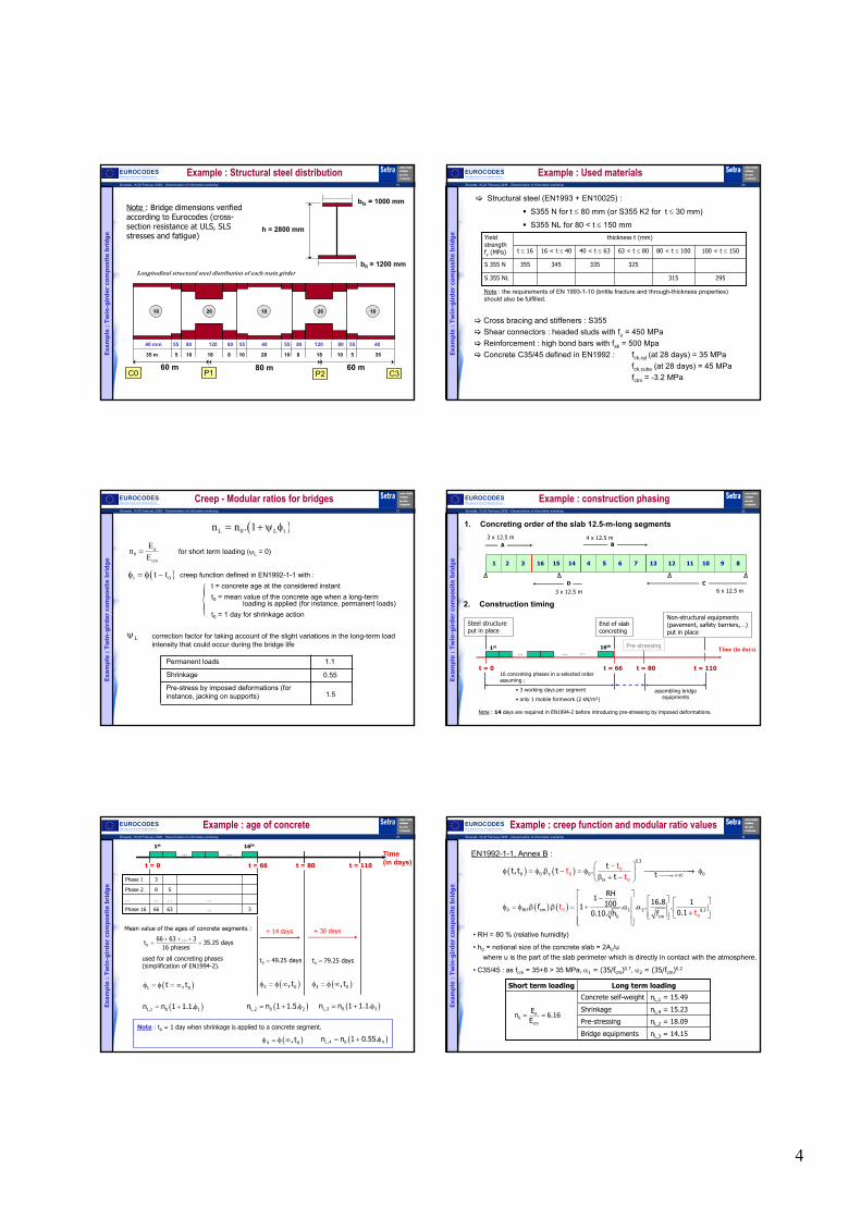
4
Brussels, 18-20 February 2008 – Dissemination of information workshop 19
EUROCODESBackground and Applications
2618 18 26 18
P1C0 P2 C360 m 60 m80 m
35 m 5 10 18 8 10 28 10 8 18 10 5 35
40 mm 55 80 120 80 55 40 55 80 120 80 55 40
h = 2800 mm
bfi = 1200 mm
bfs = 1000 mmNote : Bridge dimensions verified according to Eurocodes (cross-section resistance at ULS, SLS stresses and fatigue)
Longitudinal structural steel distribution of each main girder
Example : Structural steel distribution
Exam
ple
: T
win
-gir
der
com
pos
ite
bri
dge
Brussels, 18-20 February 2008 – Dissemination of information workshop 20
EUROCODESBackground and Applications Example : Used materials
Structural steel (EN1993 + EN10025) :
S355 N for t ≤ 80 mm (or S355 K2 for t ≤ 30 mm)
S355 NL for 80 < t ≤ 150 mm
Cross bracing and stiffeners : S355Shear connectors : headed studs with fu = 450 MPaReinforcement : high bond bars with fsk = 500 MpaConcrete C35/45 defined in EN1992 : fck,cyl (at 28 days) = 35 MPa
fck,cube (at 28 days) = 45 MPa fctm = -3.2 MPa
Exam
ple
: T
win
-gir
der
com
pos
ite
bri
dge
295315S 355 NL
325335345355S 355 N
100 < t ≤ 15080 < t ≤ 10063 < t ≤ 8040 < t ≤ 6316 < t ≤ 40t ≤ 16
thickness t (mm)Yield strength fy (MPa)
Note : the requirements of EN 1993-1-10 (brittle fracture and through-thickness properties) should also be fulfilled.
Brussels, 18-20 February 2008 – Dissemination of information workshop 21
EUROCODESBackground and Applications
( )L 0 L tn n . 1= + ψ φ
a0
cm
EnE
=
( )t 0t tφ = φ − creep function defined in EN1992-1-1 with : t = concrete age at the considered instantt0 = mean value of the concrete age when a long-term
loading is applied (for instance, permanent loads)t0 = 1 day for shrinkage action
{Lψ correction factor for taking account of the slight variations in the long-term load
intensity that could occur during the bridge life
Permanent loads
Shrinkage
Pre-stress by imposed deformations (for instance, jacking on supports)
1.1
0.55
1.5
Creep - Modular ratios for bridges
Exam
ple
: T
win
-gir
der
com
pos
ite
bri
dge
for short term loading (ψL = 0)
Brussels, 18-20 February 2008 – Dissemination of information workshop 22
EUROCODESBackground and Applications Example : construction phasing
1. Concreting order of the slab 12.5-m-long segments
Exam
ple
: T
win
-gir
der
com
pos
ite
bri
dge
3 x 12.5 m 4 x 12.5 m
6 x 12.5 m3 x 12.5 m
1 2 3 16 15 14 7 13 12 11 10 9 8654
A B
CD
2. Construction timing
Steel structure put in place
Time (in days)
t = 016 concreting phases in a selected order assuming :
• 3 working days per segment
• only 1 mobile formwork (2 kN/m²)
t = 66
End of slab concreting
t = 80
Note : 14 days are required in EN1994-2 before introducing pre-stressing by imposed deformations.
t = 110
Non-structural equipments (pavement, safety barriers,…) put in place
assembling bridge equipments
......1st 16th
...Pre-stressing
Brussels, 18-20 February 2008 – Dissemination of information workshop 23
EUROCODESBackground and Applications
t = 0
......1st 16th
Time (in days)t = 66 t = 80 t = 110
Exam
ple
: T
win
-gir
der
com
pos
ite
bri
dge
3…6366Phase 16
…………
58Phase 2
3Phase 1
Mean value of the ages of concrete segments :
used for all concreting phases (simplification of EN1994-2).
066 63 ... 3t 35.25 days
16 phases+ + +
= =
( )1 0t , tφ = φ = ∞
( )L,1 0 1n n 1 1.1.= + φ
+ 14 days
0t 49.25 days=
( )2 0, tφ = φ ∞
( )L,2 0 2n n 1 1.5.= + φ
+ 30 days
0t 79.25 days=
( )3 0, tφ = φ ∞
( )L,3 0 3n n 1 1.1.= + φ
Example : age of concrete
Note : t0 = 1 day when shrinkage is applied to a concrete segment.
( )4 0, tφ = φ ∞ ( )L,4 0 4n n 1 0.55.= + φ
Brussels, 18-20 February 2008 – Dissemination of information workshop 24
EUROCODESBackground and Applications
EN1992-1-1, Annex B :
( ) ( )0.3
0 0 c 0 00
0H
0t
tt
tt
t, t . t . t →+∞
−φ = φ β − = φ → φ β + −
( ) ( )0 RH cm 1 2 0.230 c
00m
RH1 16.8 1100. f . 1 . . . .0.
tt10.10. h f
− φ = φ β β = + α α +
• RH = 80 % (relative humidity)
• h0 = notional size of the concrete slab = 2Ac/u where u is the part of the slab perimeter which is directly in contact with the atmosphere.
• C35/45 : as fcm = 35+8 > 35 MPa, α1 = (35/fcm)0.7, α2 = (35/fcm)0.2
Exam
ple
: T
win
-gir
der
com
pos
ite
bri
dge
Example : creep function and modular ratio values
Bridge equipments
Pre-stressing
Shrinkage
Concrete self-weight
Long term loading
nL,3 = 14.15
nL,2 = 18.09
nL,4 = 15.23
nL,1 = 15.49
Short term loading
a0
cm
En 6.16
E= =

5
Brussels, 18-20 February 2008 – Dissemination of information workshop 25
EUROCODESBackground and Applications Example: shear lag in the concrete slab
60 m 80 m 60 m
C0 P1 C3P2
on support
in span 0.85x60 = 51m0.7x80 = 56m0.85x60 = 51m
0.25 x (60+80) = 35m 0.25 x (60+80) = 35m
Exam
ple
: T
win
-gir
der
com
pos
ite
bri
dge
Equivalent spans Le :
where:eff 0 1 e1 2 e2b b .b .b= + β + β eei i
Lb min ;b
8
=
i 1.0β = except at both end supports where:e
iei
L0.55 0.025 1.0
bβ = + ≤
•
•
Brussels, 18-20 February 2008 – Dissemination of information workshop 26
EUROCODESBackground and Applications
5.83 < 6.01.129 < 1.00.9482.23.251End supports C0 and C46.0/ /2.23.235Internal supports P1 and P26.0//2.23.256Span 26.0//2.23.251Spans 1 and 3
beff (m)β2β1be2be1Le (m)
Example: shear lag in the concrete slab
Exam
ple
: T
win
-gir
der
com
pos
ite
bri
dge
b1 b1=3.5 m b2=2.5 m
be1 be2
beff
b0=0.6 m
b2
=> No reduction for shear lag in the global analysis
=> Reduction for shear lag in the section analysis :
beff linearly varies from 5.83m at end supports to 6.0 m at a distance L1/4.
Brussels, 18-20 February 2008 – Dissemination of information workshop 27
EUROCODESBackground and Applications Applied loads on the road bridge example
Exam
ple
: T
win
-gir
der
com
pos
ite
bri
dge
EN1991 part 2Fatigue load model (for instance, the equivalent lorry FLM3)FLM3
EN1991 part 2Road traffic (for instance, load model LM1 with uniform design loads UDL and tandem systems TS)
UDL, TS
EN1991 part 1-5Thermal gradientTk
Variable loads
Possibly, pre-stressing by imposed deformations (for instance, jacking on internal supports)
P
Creep (taken into account through modular ratios)
EN1992 part 1-1EN1994 part 2
Shrinkage (drying, autogenous and thermal shrinkage strains)
S
EN1991 part 1-1Self weight:• structural steel• concrete (by segments in a selected order)• non structural equipments (safety barriers, pavement,…)
Gmax , Gmin
Permanent loads
Brussels, 18-20 February 2008 – Dissemination of information workshop 28
EUROCODESBackground and Applications Effects of shrinkage in a composite bridge
-
-
+ ze.n.a.
bc,eff
( ).= +σ cs cscs
steel
N z zNA I
( ),
.1. .
= − + +
σ ε cs csc cs
concrete c csc eff
N z zb NE
b n A I
1- Auto-equilibrated stress diagram in every section and an imposed rotation due to the bending moment Miso = Ncszcs :
csε
Free shrinkage strain applied on concrete slab only (no steel – concrete interaction)
cs N−
csze.n.a.
+
Shrinkage strain applied on the composite section (after steel – concrete interaction)
cs c cs c cN E .b h− = − εch
Brussels, 18-20 February 2008 – Dissemination of information workshop 29
EUROCODESBackground and Applications Effects of shrinkage in a composite bridge
2- Curvature in an isostatic bridge due to the imposed deformations :
3- Compatibility of deformations to be considered in an hyperstatic bridge :
isoMisoM
L
( )v xP1 P2
P1 P2P31L 2L
hyperM
( )v P3 0=
1+2 = isostatic (or primary) effectsEffects of shrinkage
3 = hyperstatic (or secondary) effects
Brussels, 18-20 February 2008 – Dissemination of information workshop 30
EUROCODESBackground and Applications Shrinkage and cracked global analysis
Concrete in tension
Cracked zone
isoM isoMisoM
Isostatic effects neglected in cracked zones for calculating hyperstatic effects
isoM
SLS combinations iso + hyper effects
hyper effects
hyper
hyper hyper
iso + hyper
ULS combinations
hyperM
hyperM
-
-
+-
-
+

6
Brussels, 18-20 February 2008 – Dissemination of information workshop 31
EUROCODESBackground and Applications
0.6h
400
16 °C
4 °C
-5 °C
-8 °C
+15 °C -18 °C
2- Linear gradients :1- Non linear gradients :
• could be neglected if all cross-sections are in Class 1 or 2
3- Difference +/- 10 °C : +/- 10 °C
Thermal gradient from EN 1991 part 1-5Brussels, 18-20 February 2008 – Dissemination of information workshop 32
EUROCODESBackground and Applications Traffic load LM1 from EN 1991 part 2
Exam
ple
: T
win
-gir
der
com
pos
ite
bri
dge
girder no. 2girder no. 1
3 m3 m 3 m 2 m
Lane no. 1 Lane no. 2
3.5 m 3.5 m
0.5 m1 m
Longitudinal axis of the most loaded girder Bridge axis
Safety barrier
Safety barrier
Lane no. 3Residual
area
9 kN/m²2.5 kN/m²
UDL (Uniform Design Load)
TS (Tandem System)
2 m
300 kN / axle 200 kN / axle 100 kN / axle
Characteristic values
of traffic loads from LM1
Brussels, 18-20 February 2008 – Dissemination of information workshop 33
EUROCODESBackground and Applications Combinations of actions
For every permanent design situation, two limit states of the bridge should be considered :
Serviceability Limit States (SLS)• Quasi permanent SLS
Gmax + Gmin + S + P + 0.5 Tk
• Frequent SLSGmax + Gmin + S + P + 0.75 TS + 0.4 UDL + 0.5 TkGmax + Gmin + S + P + 0.6 Tk
• Characteristic SLSGmax + Gmin + S + P + (TS+UDL) + 0.6 TkGmax + Gmin + S + P + Qlk + 0.75 TS + 0.4 UDL + 0.6 TkGmax + Gmin + S + P + Tk + 0.75 TS + 0.4 UDL
Ultime Limite State (ULS) other than fatigue1.35 Gmax + Gmin + S + P + 1.35 (TS + UDL) + 1.5 (0.6 Tk)1.35 Gmax + Gmin + S + P + 1.35 Qlk + 1.35 (0.75 TS + 0.4 UDL) + 1.5 (0.6 Tk)1.35 Gmax + Gmin + S + P + 1.5 Tk + 1.35 (0.75 TS + 0.4 UDL)
Exam
ple
: T
win
-gir
der
com
pos
ite
bri
dge
Brussels, 18-20 February 2008 – Dissemination of information workshop 34
EUROCODESBackground and Applications Un-cracked global analysis
Exam
ple
: T
win
-gir
der
com
pos
ite
bri
dge
Cracked zone on
P1
-12
-10
-8
-6
-4
-2
0
2
4
6
8
0 20 40 60 80 100 120 140 160 180 200
x = 49.7 m x = 72.5 m x = 121.6 m x = 150.6 m
17 %.L1 15.6 %.L2 23 %.L2 17.7 %.L3
2. 6.4 MPa− = −ctmf
x (m)
σ (MPa) : Stresses in the extreme fibre of the concrete slab, under Characteristic SLS combination when considering concrete resistance in every cross-section
L1 = 60 m L2 = 80 m L3 = 60 m
Note : Dissymmetry in the cracked lengths due to sequence of slab concreting.
EI2 EI2EI1 EI1EI1
Cracked zone on P2
Brussels, 18-20 February 2008 – Dissemination of information workshop 35
EUROCODESBackground and Applications Cracked global analysis: bending moments
Exam
ple
: T
win
-gir
der
com
pos
ite
bri
dge
37.5937.06 41.33
-80.69 -77.66
50.8456.0750.16
-103.54-107.25-120
-100
-80
-60
-40
-20
0
20
40
60
80
0 20 40 60 80 100 120 140 160 180 200
ELS caractéristiqueELU fondamental
Ben
din
g m
omen
t (M
N.m
)
Fundamental ULSCharacteristic SLS
x (m)
Brussels, 18-20 February 2008 – Dissemination of information workshop 36
EUROCODESBackground and Applications
Exam
ple
: T
win
-gir
der
com
pos
ite
bri
dge
Cracked global analysis: shear forces
5.54 5.49
3.24
-5.49-5.54
-3.26
1.09
7.47 7.39
4.38
-3.09 -2.92
-7.46 -7.41
-4.40
3.09
-10
-8
-6
-4
-2
0
2
4
6
8
10
0 20 40 60 80 100 120 140 160 180 200
ELS caractéristiqueELU fondamentalFundamental ULS
Characteristic SLS
x (m)
Shea
r fo
rce
(MN
)

7
Brussels, 18-20 February 2008 – Dissemination of information workshop 37
EUROCODESBackground and Applications Contents : 7 parts
1. Introduction to composite bridges in Eurocode 4
2. Global analysis of composite bridges
3. ULS verifications
4. SLS verifications
5. Connection at the steel–concrete interface
6. Fatigue (connection and reinforcement)
7. Lateral Torsional Buckling of members in compression
Brussels, 18-20 February 2008 – Dissemination of information workshop 38
EUROCODESBackground and Applications ULS verifications of a composite bridge
• resistance of the composite cross-sections
- for bending moment M (EN 1994-2, 6.2.1)
- for shear force V (EN 1994-2, 6.2.2.1 to 6.2.2.3)
- for interaction M+V (EN 1994-2, 6.2.2.4)
• shear resistance in the concrete slab (EN 1994-2, 6.2.2.5(3) )
• concrete slab (EN 1992)
• shear connection (see below, point 5)
• fatigue ULS (see below, point 6)
• LTB around intermediate supports (see below, point 7)
Brussels, 18-20 February 2008 – Dissemination of information workshop 39
EUROCODESBackground and Applications
p.n.a
e.n.a
Elastic resistance(for classes 1 to 4)
Plastic resistance(for classes 1 and 2)
0.85 fck/γc
fy/γM
(+)
(−)
fck/γc
(+)
fy/γM
(−)
compression
tension
ULS section resistance under M > 0
e.n.a. = elastic neutral axis
p.n.a. = plastic neutral axis
Brussels, 18-20 February 2008 – Dissemination of information workshop 40
EUROCODESBackground and Applications
p.n.a
e.n.a
Elastic resistance(for classes 1 to 4)
Plastic resistance(for classes 1 and 2)
compression
tension fsk/γs
(−)
fy/γM
(+)
fy/γM
0.85 fck/γc
(−)
(+)
fy/γM
fsk/γs
ULS section resistance under M < 0
Brussels, 18-20 February 2008 – Dissemination of information workshop 41
EUROCODESBackground and Applications Class 4 composite section with construction phases
• Use of the final ULS stress distribution to look for the effective cross-section
• If web and flange are Class 4 elements, the flange gross area is first reduced. The corresponding first effective cross-section is used to re-calculate the stress distribution which is then used for reducing the web gross area.
a,EdM
+
c,EdM
=
Ed a,Ed c,EdM M M= +
Recalculation of the stress distributionrespecting the sequence of construction
1- Flange
2- Web
eff eff effA ,I ,G
Justification of the recalculated stress distribution
Brussels, 18-20 February 2008 – Dissemination of information workshop 42
EUROCODESBackground and Applications
• For Class 1 or 2 sections :
– If VEd< 0.5.VRd, no interaction occurs.
– If not, the criterion MEd < Mpl,Rd is verified using a reduced Mpl,Rd value
• For Class 3 or 4 sections : See Eurocode 3 part 1-5.
Plastic resistance : ensured by the steel web Vpl,a,Rd is calculated by using Eurocode 3 part 1-1.
Shear buckling resistance :
See Eurocode 3 part 1-5.
Interaction between M and V :
ULS resistance under V and interaction M + V
yw w wRd b,Rd bw,Rd bf ,Rd
M1
f h tV V V V
3η
= = + ≤γ
yRd pl,a ,Rd V
M0
fV V A .
3= =
γ
2
Ed
Rd
V2 1V
η = −

8
Brussels, 18-20 February 2008 – Dissemination of information workshop 43
EUROCODESBackground and Applications
• For the solid slab of a composite bridge:
Ed Rd,cV V≤ => Shear reinforcement (Ast for b = 1 m) is not necessary (nor the minimum shear reinforcement area according to EN1992-2,9.2.2)
1 3Rd,c Rd,c l ck 1 cp c min 1 cp cV C k(100 f ) k bh (v k )bh = ρ + σ ≥ + σ
Rd,cC
0.15C 0.12= =
γ1k 0.12=
c
200k 1
h= +
stl
c
Abh
ρ =
Edcp,0 cp
c
N1.85 MPa
bhσ = − ≤ σ =
1.5min ckv 0.035.k f=
ULS shear resistance in the concrete slab
• If the concrete flange is in tension :
-10
-8
-6
-4
-2
0
2
4
6
8
10
0 20 40 60 80 100 120 140 160 180 200
x (m)
Stre
sses
in th
e sl
ab a
t ULS
(MPa
)
Lower fibreUpper fibresigma_cp,0
Brussels, 18-20 February 2008 – Dissemination of information workshop 44
EUROCODESBackground and Applications
Exam
ple
: T
win
-gir
der
com
pos
ite
bri
dge
60 m 80 m 60 m
AΣ BΣ
Concrete in tension
M<0
Class 3 (elastic section analysis)
MULS = -107.25 MN.m
VULS = 7.47 MN
Section AΣConcrete in compression
M>0
Class 1 (plastic section analysis)
MULS = +56.07 MN.m
VULS = 1.04 MN
Section BΣ
Example: Analysis of 2 different cross-sections
Brussels, 18-20 February 2008 – Dissemination of information workshop 45
EUROCODESBackground and Applications
Exam
ple
: T
win
-gir
der
com
pos
ite
bri
dge
Example: Cross-section ΣA under bending
-171.2 MPa-149.2 MPa
-275.8 MPa
261.3 MPa
2.5 m 3.5 m
Stress diagram under bending
ysteel,inf
M0
f295 MPaσ ≤ =
γ
ysteel,sup
M0
f295 MPa− = − ≤ σ
γ
skre inf .
S
f434.8 MPa− = − ≤ σ
γ
1000 x 120 mm²
1200 x 120 mm²2560 x 26 mm²
Elastic section analysis :
Brussels, 18-20 February 2008 – Dissemination of information workshop 46
EUROCODESBackground and Applications Example: Cross-section ΣA under shear force
2
whk 5.34 4 5.75
aτ = + =
cr Ek 19.58 MPaττ = σ =
hw = 2560 mm
a = 8000 mm
First cross-bracing in central spanP1
VEd = 7.47 MN
VEd = 6.00 MN
tw = 26 mm
w
w
h 31k
t τ
ε≥
η
Shear buckling to be considered:
yw w wRd b,Rd bw,Rd bf ,Rd
M1
f h tV V V V
3
η= = + ≤
γ
Contribution of the flange Vbf,RdContribution of the web Vbw,Rd
yww
cr
f1.33 1.08
3λ = = ≥
τ
ww
1.370.675
0.7χ = =
+ λ
ywbw,Rd w w w
M1
fV h t 8.14 MN
3= χ =
γ
bf ,RdV 0.245 MN= can be neglected.
Exam
ple
: T
win
-gir
der
com
pos
ite
bri
dge
Brussels, 18-20 February 2008 – Dissemination of information workshop 47
EUROCODESBackground and Applications Example: Cross-section ΣA under M+V interaction
Exam
ple
: T
win
-gir
der
com
pos
ite
bri
dge
Ed
Rd
V0.5
V≥ so the M+V interaction should be checked, and as the section is in
Class 3, the following criterion should be applied (EN1993-1-5) :
2f ,Rd1 3
pl,Rd
M1 2 1 1.0
M
η + − η − ≤
at a distance hw/2 from internal support P1.
f ,RdM 117.3 MN.m= : design plastic resistance to bending of the effective composite section excluding the steel web (EN 1994-2, 6.2.2.5(2)).
f ,RdEd1
pl,Rd pl,Rd
MM0.73 0.86
M Mη = = ≤ =
Ed3
bw,Rd
V0.89
Vη = =
pl,RdM 135.6 MN.m= : design plastic resistance to bending of the effective composite section.
As MEd < Mf,Rd, the flanges alone can be used to resist M whereas the steel web resists V.
=> No interaction !
Brussels, 18-20 February 2008 – Dissemination of information workshop 48
EUROCODESBackground and Applications
Exam
ple
: T
win
-gir
der
com
pos
ite
bri
dge
Example: Cross-section ΣB (Class 1)
9.2 MPa
202.0 MPa
-305.2 MPa
2.5 m 3.5 m
p.n.a.+
-
ck
C
f0.85
γ
yf
M0
fγ
yw
M0
f−
γ
1000 x 40 mm²
1200 x 40 mm²
2720 x 18 mm²
Plastic section analysis under bending : Ed pl,RdM 56.07 M 79.59 MN.m= ≤ =2
whk 5.34 4 5.80
aτ = + =
w
w
h 31k
t τ
ε≥
η, so the shear buckling has to be considered:
yw w wEd Rd b,Rd bw,Rd bf ,Rd bw,Rd
M1
f h tV 2.21 MN V V V V V 4.44 MN 10.64 MN
3
η= ≤ = = + ≈ = ≤ =
γ
and
Ed
Rd
V0.5
V≤ => No M+V interaction !

9
Brussels, 18-20 February 2008 – Dissemination of information workshop 49
EUROCODESBackground and Applications Contents : 7 parts
1. Introduction to composite bridges in Eurocode 4
2. Global analysis of composite bridges
3. ULS verifications
4. SLS verifications
5. Connection at the steel–concrete interface
6. Fatigue (connection and reinforcement)
7. Lateral Torsional Buckling of members in compression
Brussels, 18-20 February 2008 – Dissemination of information workshop 50
EUROCODESBackground and Applications SLS verifications in a composite bridge
• Limitation of stresses in cross-sections at characteristic SLS
• Crack width control
• Limitations of deflections (national regulations)
• Web breathing (fatigue phenomenon, see EN1993-2)
Note : for shear connectors, see section 5 below
M>0
c ck0.6.fσ ≤ (concrete in compression)
a yk1.0.fσ ≤
M<0
s sk0.8.fσ ≤
a yk1.0.fσ ≤
(reinforcement in tension)
Brussels, 18-20 February 2008 – Dissemination of information workshop 51
EUROCODESBackground and Applications
1. Minimum reinforcement required
- in cross-sections where tension exists in the concrete slab for characteristic SLS combinations of actions
- estimated from equilibrium between tensile force in concrete just before cracking and tensile force in the reinforcement (at yielding or at a lower stress level if necessary to limit the crack width)
2. Control of cracking due to direct loadingThe design crack width wk should be limited to a maximum crack width wmaxby limiting :
- bar spacing s ≤ smax
- or bar diameter Φ ≤ Φmax
wmax depends on the exposure class of the considered concrete face
smax and Φmax depend on the calculated stress level σs = σs,0 + ∆σs in the reinforcement and on the design crack width wk
Crack width control
3. Control of cracking due to indirect loadingFor instance, concrete shrinkage.
Brussels, 18-20 February 2008 – Dissemination of information workshop 52
EUROCODESBackground and Applications
* : for bridges near sea water
** : for bridges subjected to (very) frequent salting
*** : for the bottom surface of a bridge deck located within 6 m above a road with (very) frequent salting
XC3, XS1*
XC4, XS1*, XD3***
waterproofing layer
XC4, XS1*, XD3**,
XF1 or XF2**
XC4, XS1*, XD3**, XF3 or XF4**
XC4, XS1*, XD3***,
XF1 or XF2**
Mechanical abrasionXM
Chemical attackXA1 to XA3
Freeze/thaw attackXF1 to XF4Attack to concrete
Corrosion induced by chlorides from sea waterXS1 to XS3
Corrosion induced by chloridesXD1 to XD3
Corrosion induced by carbonationXC1 to XC4Risk of corrosion of reinforcement
No risk of corrosion or attack of concreteXO
Description of the environmentClass
Exposure classes for composite bridges (durability)
Brussels, 18-20 February 2008 – Dissemination of information workshop 53
EUROCODESBackground and Applications Exposure classes for composite bridges (durability)
XC3
XC4
waterproofing layer
XC4, XF1
XC4, XF3
XC4, XF1
Hypothesis : Bridge in a low-level frost areaThe choice of exposure classes leads to define :
• a minimum resistance for concrete (according to EN1992 and EN206), for instance C30/37
• a concrete makeup (maximum E/C ratio, minimum cement content) according to EN206
• a structural class (S1 to S6) for every face of the slab, chosen according to Table 4.3 in EN1992 and to the retained concrete
• a minimum concrete cover for every face of the slab according to the exposure class and the structural class
Exam
ple
: T
win
-gir
der
com
pos
ite
bri
dge
Brussels, 18-20 February 2008 – Dissemination of information workshop 54
EUROCODESBackground and Applications
hc
z0
e.n.a.calculated with n0
fct,eff
change in the location of the
neutral axis
before cracking
after cracking
σsσc
s c ct,eff ct s sk k. k f A A = σ
cc
0
1k 0.3 1.0
h1
2z
= + ≤+
stress distribution within the tensile concrete height hc before cracking (including indirect loading) + change in the location of the neutral axis at cracking time
reduction of the normal force in the concrete slab due to initial cracking and local slip of the shear connection
ks = 0.9
k = 0.8 effect of non-uniform shape in the self-equilibrating stresses within hc
Minimum reinforcement
fct,eff = fctm σs = fskand give the minimum reinforcement section As,min.

10
Brussels, 18-20 February 2008 – Dissemination of information workshop 55
EUROCODESBackground and Applications Example : minimum reinforcement
Exam
ple
: T
win
-gir
der
com
pos
ite
bri
dge
The elastic neutral axis is located in the steel web for every section of the bridge, so Act is the slab section : Act = 6 x 0.34 = 2.04 m²
hc = 0.34 m
fct,eff = fctm = -3.2 Mpa
z0 = 0.52 m
cc
0
1k min 0.3;1.0 1.0
h1
2z
= + = +
fsk = 500 MPa
As,min = 94 cm² which means a minimum reinforcement ratio s,min 0.46%ρ =
For the design, the following reinforcement ratios have been considered :
• Top layer : high bonded bars with φ = 16 mm and s = 130 mm, so
• Bottom layer : high bonded bars with φ = 16 mm and s = 130 mm, so
s,top 0.46%ρ =
s,bottom 0.46%ρ =
We verify : s,top s,bottom s,min0.92%ρ + ρ = ≥ ρ
Brussels, 18-20 February 2008 – Dissemination of information workshop 56
EUROCODESBackground and Applications
Recommended values defined in EN1992-2 (concrete bridges) :
Maximum crack width wmax
The stress level σs,0 in the reinforcement is calculated for the quasi-permanent SLScombination of actions (in case of reinforced concrete slab).
The tension stiffening effect ∆σs should be taken into account.
Brussels, 18-20 February 2008 – Dissemination of information workshop 57
EUROCODESBackground and Applications
Ast is put in place through n high bonded bars of diameter φ per meter.
or
Diameter φ∗
(Table 7.1)
Spacing s = 1/n
(Table 7.2)
Crack width control
ct ,eff* f2.9 MPa
Φ = Φ
Brussels, 18-20 February 2008 – Dissemination of information workshop 58
EUROCODESBackground and Applications
Exam
ple
: T
win
-gir
der
com
pos
ite
bri
dge
The stress level σs due to direct loading at quasi-permanent SLS combinations of actions can be calculated :
• Top and bottom layers : Ast with φ = 16 mm and s = 130 mm, so
• σs,0 = 106 Mpa (maximum tension) at quasi-permanent SLS in the top layer
-150
-100
-50
-
50
100
0 20 40 60 80 100 120 140 160 180 200
x (m)
Stre
sses
at Q
P SL
S (M
Pa)
Stresses in the upper layer of reinforcement, calculated by neglecting concrete resistance (in tension).
Example : crack width control for direct loading
s,top s,bottom 0.46%ρ = ρ =
Brussels, 18-20 February 2008 – Dissemination of information workshop 59
EUROCODESBackground and Applications
Exam
ple
: T
win
-gir
der
com
pos
ite
bri
dge
Example : crack width control for direct loading
• Tension stiffening effect :
• in the considered cross-section (where σs,0 is maximum) :
ctms
s st
f0.4∆σ =
ρ α
sta a
AI1.31
A Iα = = s 0.92%ρ = (Reinforcement ratio)
ctms
s st
f0.4 106.2 MPa∆σ = =
ρ α•
•
•
•
•
•
s s,0 s 212.2 MPaσ = σ + ∆σ =
*max 22.3 mmΦ = (interpolation in Table 7.1 of EN 1994-2)
*max max16 mm 3.2 /2.9 24.6 mmΦ = ≤ Φ = Φ =
maxs 235 mm= (interpolation in Table 7.2 of EN 1994-2)
or
maxs 130 mm s 235 mm= ≤ =
Brussels, 18-20 February 2008 – Dissemination of information workshop 60
EUROCODESBackground and Applications Example : crack width control for indirect loading
The stress level σs due to indirect loading (for instance, concrete shrinkage) can not be calculated in the reinforcement.
In the sections where the concrete slab is in tension for characteristic SLS combinations of actions, σs is estimated using :
cts s c ct,eff
s
A 2.04k kk f 0.9 0.8 1.0 3.2 250.4 MPa
A 0.92% 2.04σ = = =
Exam
ple
: T
win
-gir
der
com
pos
ite
bri
dge
The reinforcement layers are designed using high bonded bars with φ = 16 mm.
φ∗ = φ fct,eff/fct,0 = 2.9/3.2 = 14.5 mm
The interpolation in Table 7.1 from EN 1994-2 gives : σs,max = 255 Mpa
We verify :
σs = 250.4 Mpa < σs,max = 255 Mpa

11
Brussels, 18-20 February 2008 – Dissemination of information workshop 61
EUROCODESBackground and Applications Contents : 7 parts
1. Introduction to composite bridges in Eurocode 4
2. Global analysis of composite bridges
3. ULS verifications
4. SLS verifications
5. Connection at the steel–concrete interface
6. Fatigue (connection and reinforcement)
7. Lateral Torsional Buckling of members in compression
Brussels, 18-20 February 2008 – Dissemination of information workshop 62
EUROCODESBackground and Applications Steel-concrete connection
• Full interaction required for bridges
• Elastic resistance design of the shear connectors at SLS and at ULS
• Plastic resistance design of the shear connectors at ULS in Class 1 or 2 cross sections where Mel,Rd ≤ MEd ≤ Mpl,Rd
• Shear connectors locally added due to concentrated longitudinal shear force (for instance, shrinkage and thermal action at both bridge deck ends or cable anchorage)
• ULS design of transverse reinforcement to prevent longitudinal shear failure or splitting in the concrete slab
Objective :
Transmit the longitudinal shear force vL,Ed per unit length of the steel-concrete interface
Performed by the use of shear connectors (only studs in EN1994) and transverse reinforcement
Brussels, 18-20 February 2008 – Dissemination of information workshop 63
EUROCODESBackground and Applications Resistance of the headed stud shear connector
• Shank shear resistance :
• Concrete crushing :
16 d 25mm≤ ≤
1.5d≥
0.4d≥
h 3d≥
t
d
2(1)
Rk udP 0.8f .4
π=
(2) 2
Rk ck cmP 0.29 d f E= α
s Rdk .P
RkRd
V
PP =γ
National AnnexDesign resistanceLimit State
U.L.S.
S.L.S.
V 1.25γ =
sk 0.75=
(1) (2)Rk Rk RkP min P ;P =
h0.2 1d
α = +
ifh3 4d
≤ ≤ , then
else 1α =
Brussels, 18-20 February 2008 – Dissemination of information workshop 64
EUROCODESBackground and Applications Elastic design of the shear connection
• SLS and ULS elastic design using the shear flow vL,Ed at the steel-concrete interface, which is calculated with an uncracked behaviour of the cross sections.
SLS ULS
( ) { }, .≤SLS iL Ed s Rd
i
Nv x k Pl
For a given length li of the girder (to be chosen by the designer), the Nishear connectors are uniformly distributed and satisfy :
For a given length li of the girder (to be chosen by the designer), the Ni
* shear connectors are uniformly distributed and satisfy :
( )*
, 1.1 .≤ULS iL Ed Rd
i
Nv x Pl
( )0 ≤ ≤ ix l ( ) *,
0
.≤∫il
ULSL Ed i Rdv x dx N P
( ), ( ). += Ed
c sL
c sEd
A zv x AV zxI
Shear force from cracked global
analysisUncracked
mechanical properties
2.5 m 3.5 m
e.n.a.sz
cz
Brussels, 18-20 February 2008 – Dissemination of information workshop 65
EUROCODESBackground and Applications Example : SLS elastic design of connectors
Exam
ple
: T
win
-gir
der
com
pos
ite
bri
dge
0
0.2
0.4
0.6
0.8
1
1.2
1.4
0 20 40 60 80 100 120 140
Shear flow at SLS (MPa/m)Shear resistance of the studs (MPa/m)
L1 = 29 m L2 = 41 m L3 = 41 m L4 = 29 m
Studs with :
d = 22 mm
h = 150 mm
in S235
L,Edv SLS
in MPa/m
Brussels, 18-20 February 2008 – Dissemination of information workshop 66
EUROCODESBackground and Applications
Exam
ple
: T
win
-gir
der
com
pos
ite
bri
dge
Example : ULS elastic design of connectors
0
0.2
0.4
0.6
0.8
1
1.2
1.4
1.6
0 20 40 60 80 100 120 140
Shear flow at ULS (MPa/m)Shear resistance of the studs (MPa/m)
• Using the same segment lengths li as in SLS calculation and the same connector type
L,Edv ULS
in MPa/m

12
Brussels, 18-20 February 2008 – Dissemination of information workshop 67
EUROCODESBackground and Applications
Exam
ple
: T
win
-gir
der
com
pos
ite
bri
dge
Example : longitudinal spacing of studs rows
0
100
200
300
400
500
600
700
800
0 20 40 60 80 100 120 140
spacing at SLS (mm)spacing at ULS (mm)
x (m)
e (mm)
=> Elastic design governed by ULS.
Brussels, 18-20 February 2008 – Dissemination of information workshop 68
EUROCODESBackground and Applications
• Eventually adding shear connectors in the elasto-plastic zoneswhere Mpl,Rd > MEd > Mel,Rd
Elasto-plastic design (ULS) of the shear connection
• NB (or NB*) is determined by
using an interaction M-N diagram in the section B.
•
connectors to put between sections A and B.
P1 B
Mpl,Rd
MEd
A
First yielding in at least one fibre of the cross-section
where MEd = Mel,Rd
Elasticdesign
Elasto-plastic design
NA
P2C
NB
Elasto-plastic zone
( )*B B A
Rk V
N or N Nn
P
−=
γ
Brussels, 18-20 February 2008 – Dissemination of information workshop 69
EUROCODESBackground and Applications Interaction diagram in the cross-section B
• Two options : simplified diagram (straight line GH) / more precise diagram (broken line GJH)
NB (N)
MB (N.m)
Mpl,RdMEdMel,Rd
Ma,Ed
Nel,B NB Npl,BNB*0
GG
JJ
HH
ckpl,B eff c
C
0.85.fN .b .h=γ
• Plastic resistance of the concrete slab (within the effective width) to compressive normal force :
Brussels, 18-20 February 2008 – Dissemination of information workshop 70
EUROCODESBackground and Applications
+ k . =
Step 1 : stress diagram for load cases applied to the structure beforeconcreting Section B
Step 2 : stress diagram for load cases applied to the structure after concreting Section B
Step 3 : ULS stress diagram in Section B (if yielding is reached in the extreme bottom fibre)
σai(1) σai
(2) σai
σas(1) σas
(2) σas
σc(2) σc
fyk
fyk
fcd=fck/γc
k (< 1) is the maximum value for keeping step 3 within its elastic strength limits. =>
Elastic resistance moment in the section B
MMa,a,EdEd ++ MMc,c,EdEd == MMEdEd
(For instance, σai(1) + k.σai
(2) = fyk )Mel,Rd = Ma,Ed + k. Mc,Ed
Brussels, 18-20 February 2008 – Dissemination of information workshop 71
EUROCODESBackground and Applications
-50
-40
-30
-20
-10
0
10
20
30
40
50
0 20 40 60 80 100 120 140
M_Ed+
M_Ed-
M_pl,Rd+
M_pl,Rd -
Example : Bending moment in section B
Ma,Ed(B) = 2.7 MN.m -----> MEd(B) = 22.3 MN.m < Mpl,Rd (B) = 25.7 MN.m
Exam
ple
: T
win
-gir
der
com
pos
ite
bri
dge Section B
(Class 1)
x (m)
1 2 3 4 5 6 7 8 910111213141516
Concreting phases
M (M
N.m
)
Brussels, 18-20 February 2008 – Dissemination of information workshop 72
EUROCODESBackground and Applications
Exam
ple
: T
win
-gir
der
com
pos
ite
bri
dge
Example : Normal stresses in section B
Mc,Ed(B) = 22.3 – 2.7 = 19.6 MN.m
σai(2) = (-360.3) – (-63.0) = -297.3 Mpa
k is defined by ( )− −
= = ≤σ
y(2)
ai
f 63.0k 0.95 1.0
Mel,Rd is then defined by Mel,Rd = Ma,Ed + k. Mc,Ed = 21.3 MN.m
-63.0 MPa σai(2)
σas(2)
σc11.9 MPa
151.7 MPa
-360.3 MPa
Ma,Ed(B) = 2.7 MN.m MEd(B) = 22.3 MN.mMc,Ed(B)
88.2 MPafy = -345 MPa

13
Brussels, 18-20 February 2008 – Dissemination of information workshop 73
EUROCODESBackground and Applications Example : Interaction diagram in section B
26.9 cm
3.6 cm
beff = 5.6 m
0.65 m
0.95*11.9 MPa
0.95*3.0 MPa
Nel = 11.4 MN
k * ULS stresses
=γck
C
f0.85 19.8 MPa
= =γck
pl c,effC
fN 0.85 .A 30.3 MPa
NB (MN)
MB (MN.m)
Mpl,Rd = 25.7MEd = 22.3
Mel,Rd = 21.3
MaEd = 2.7
Nel = 11.4 NB = 25.8Npl = 30.3
NB* = 15.7
0
Exam
ple
: T
win
-gir
der
com
pos
ite
bri
dge
Brussels, 18-20 February 2008 – Dissemination of information workshop 74
EUROCODESBackground and Applications
Exam
ple
: T
win
-gir
der
com
pos
ite
bri
dge
-400
-300
-200
-100
0
100
200
300
400
0 20 40 60 80 100 120 140
ULS Stresses (MPa) in the bottom steel flange
fy
Section CSection A
Section B
(σmax = -360.3 Mpa)
fy = -345 MPa
3.3 m 2.8 m
Example : Limits of the elasto-plastic zone
26.9 cm
3.6 cm
beff = 5.6 m
0.65 m
11.8 MPa
3.1 MPa
11.3 MPa
2.9 MPa
Nel(C) = 11.5 MNNel(A) = 12.1 MN
Section A Section C
Brussels, 18-20 February 2008 – Dissemination of information workshop 75
EUROCODESBackground and Applications Adding shear connectors by elasto-plastic design
• 9 rows with 4 studs and a longitudinal spacing equal to 678 mm (designed at ULS)
(15.7-11.5)/(4x0.1095) = 10 rows
spacing = 2800/10 = 280 mm
(15.7-12.1)/(4x0.1095) = 9 rows
spacing = 3300/9 = 367 mm
More precise interaction
diagram
(25.8-11.5)/(4x0.1095) = 33 rows
spacing = 2800/33 = 84 mm(which is even lower than 5d=110 mm !)
(25.8-12.1)/(4x0.1095) = 28 rows
spacing = 3300/28 = 118 mm
Simplified interaction
diagram
Exam
ple
: T
win
-gir
der
com
pos
ite
bri
dge
Section B Section CSection A
3300 mm 2800 mm
e = 678 mm
Brussels, 18-20 February 2008 – Dissemination of information workshop 76
EUROCODESBackground and Applications
•
• for a structural steel flange in tension, subjected to fatigue
•
•
•
Detailing for shear connectors
25 mm ≤ De• to allow a correct welding of the connector :
2 5≤ fd . .t1 5≤ fd . .td h
tf
• for solid slabs :
3≥h d1 5≥head . dΦ0 4≥headh . d
• and if the used shear connectors are studs :
Brussels, 18-20 February 2008 – Dissemination of information workshop 77
EUROCODESBackground and Applications
Longitudinal spacing between shear connectors rows
– to insure the composite behaviour in all cross-sections :emax = min (800 mm; 4 h )where h is the concrete slab thickness
– if the structural steel flange in compression which is connected to the concrete slab, is a class 3 or 4 element :
• to avoid buckling of the flange between two studs rows :
• to avoid buckling of the cantilever eD-long part of the flange :
– and if the used shear connectors are studs :
Transversal spacing between adjacent studs
max fy
235e 22tf
≤
Detailing for shear connectors
min5.d e≤
2 5≥trans ,mine . .d
2359≤D fy
e tf
4≥trans ,mine .d
for solid slabs
in other cases
Brussels, 18-20 February 2008 – Dissemination of information workshop 78
EUROCODESBackground and Applications Transverse reinforcement for solid slabs
Truss model for transverse reinforcement which supplements the shear strength of the concrete on potential surface of failure (a-a for instance)
1aa L,Ed
eff
bv v ULS .
b=
compression
tension
com
pres
sion
fθ
L,Edv
cracksa
ab1
beff
1m Ab+At
a
ab1
beff
Transverse reinforcement
Ab
At
hc

14
Brussels, 18-20 February 2008 – Dissemination of information workshop 79
EUROCODESBackground and Applications Transverse reinforcement for solid slabs
• tension in reinforcement :
• compression in concrete struts :
• for slab in tension at ULS : (or )
• for slab in compression at ULS : (or )
• Other potential surfaces of shear failure defined in EN1994-2 :
( )aa c f b t sdv .h .(1m).tan A A .fθ ≤ +
ckaa cd f f
fv 0.6 1 f .sin cos
250 ≤ − θ θ
f1.0 co tan 1.25≤ θ ≤f38.6 45° ≤ θ ≤ °
f1.0 co tan 2.0≤ θ ≤ f26.5 45° ≤ θ ≤ °
Brussels, 18-20 February 2008 – Dissemination of information workshop 80
EUROCODESBackground and Applications Contents : 7 parts
1. Introduction to composite bridges in Eurocode 4
2. Global analysis of composite bridges
3. ULS verifications
4. SLS verifications
5. Connection at the steel–concrete interface
6. Fatigue (connection and reinforcement)
7. Lateral Torsional Buckling of members in compression
Brussels, 18-20 February 2008 – Dissemination of information workshop 81
EUROCODESBackground and Applications Fatigue ULS in a composite bridge
In a composite bridge, fatigue verifications shall be performed for :
• the structural steel details of the main girder (see EN1993-2 and EN1993-1-9)
• the slab concrete (see EN1992-2)
• the slab reinforcement (see EN1994-2)
• the shear connection (see EN1994-2)
Two assessment methods in the Eurocodes which differ in the partial factor γMf for fatigue strength in the structural steel :
Safe lifeNo requirement for regular in-service inspection for fatigue damage
Damage tolerantRequired regular inspections and maintenance for detecting and repairing fatigue damage during the bridge life
High consequenceLow consequence
Consequence of detail failure for the bridgeAssessment method(National Choice)
Mf 1.0γ = Mf 1.15γ =
Mf 1.15γ = Mf 1.35γ =
Brussels, 18-20 February 2008 – Dissemination of information workshop 82
EUROCODESBackground and Applications Damage equivalent stress range ∆σE
In a given structural detail of the bridge which is subjected to repeated fluctuations of stresses due to traffic loads, a fatigue crack could initiate and propagate. The detail fails when the damage D in it reaches 1.0 :
crack
Longitudinal stiffener on a web
weld
∆σ
In term of D, the actual traffic (ni, ∆σi)i is equivalent to nE = Σ ni cycles of the unique equivalent stress range ∆σE.
i
i
nD
N= ∑Total damage in the detail :
damage Log N (cycles)
Log ∆σ (stress range)
ni Niii
i
nd
N=
Fatigue S-N curve of the studied detail (EN1993-2)
with 2 slopes (m=3 and m=5)
NC = 2.106
∆σC
ND=5.106 NL=100.106
1m
mN C. −= ∆σ
Brussels, 18-20 February 2008 – Dissemination of information workshop 83
EUROCODESBackground and Applications Fatigue Load Model 3 « equivalent lorry » (FLM3)
axle = 120 kN
E p.∆σ = λΦ ∆σ
• 2.106 FLM3 lorries are assumed to cross the bridge per year and per slow lane defined in the project
• every crossing induces a stress range ∆σp = |σmax,f - σmin,f | in a given structural detail
• the equivalent stress range ∆σE in this detail is obtained as follows :
where :
• λ is the damage equivalence factor
• Φ is the damage equivalent impact factor (= 1.0 as the dynamic effect is already included in the characteristic value of the axle load)
Brussels, 18-20 February 2008 – Dissemination of information workshop 84
EUROCODESBackground and Applications Damage equivalence factor λ
In a structural steel detail (in EN 1993-2):λ=λ1 λ2 λ3 λ4 < λmaxwhich represents the following parameters :
λ1 : influence of the loaded lengths, defined in function of the bridges spans (< 80 m) and the shape of the influence line for the internal forces and moments
λ2 : influence of the traffic volume
λ3 : life time of the bridge ( λ3=1 for 100 years)
λ4 : influence of the number of loaded lanes
λmax : influence of the constant amplitude fatigue limit ∆σD at 5.106 cycles
For shear connection (in EN1994-2):
For reinforcement (in EN1992-2):
For concrete in compression (in EN1992-2 and only defined for railway bridges):
v v,1 v,2 v,3 v,4. . .λ = λ λ λ λ
s fat s,1 s,2 s,3 s,4. . . .λ = ϕ λ λ λ λ
c c,0 c,1 c,2,3 c,4. . .λ = λ λ λ λ

15
Brussels, 18-20 February 2008 – Dissemination of information workshop 85
EUROCODESBackground and Applications Example : Damage equivalence factor λv
Exam
ple
: T
win
-gir
der
com
pos
ite
bri
dge
• for road bridges (with L< 100 m) : v,1 1.55λ =
• hypothesis for the traffic volume in the example (based for instance on the existing traffic description in EN 1991 part 2):
Mean value of lorries weight :
(1 8)
obsmlv,2 6
NQ 4070.848
480 0.5.10 480 λ = = =
1 55i i
mli
nQQ 407 kN
n
= =
∑∑
• bridge life time = 100 years, so v,3 1.0λ =
6obsN 0.5.10= lorries per slow lane and per year with the following distribution
1Q 200 kN= 2Q 310 kN= 3Q 490 kN= 4Q 390 kN= 5Q 450 kN=
40% 10% 30% 15% 5%
• only 1 slow lane on the bridge, so v,4 1.0λ = v 1.314λ =
Brussels, 18-20 February 2008 – Dissemination of information workshop 86
EUROCODESBackground and Applications
Stress range ∆σp = | σmax,f – σmin,f | in the structural steel
FLM3+
In every section :
Fatigue loadsBasic combination of non-cyclic actions
max min kG (or G ) 1.0 (or 0.0)S 0.6T+ +
max min a,Ed c,EdM (or M ) M M= + FLM3,max FLM3,minM and M
Ed,max,f a,Ed c,Ed FLM3,maxM M M M= + +Ed,min,f a,Ed c,Ed FLM3,minM M M M= + +
L 0
1 1c,Ed,max,f c,Ed FLM3,max
1 1n n
v vM M
I I
σ = + L 0
1 1c,Ed,min,f c ,Ed FLM3,min
1 1n n
v vM M
I I
σ = +
• Bending moment in the section where the structural steel detail is located :
• Corresponding stresses in the concrete slab (participating concrete) :
σc,Ed,max,f > 0σc,Ed,min,f < 0
Case 3
σc,Ed,max,f < 0σc,Ed,min,f < 0
Case 2
σc,Ed,max,f > 0σc,Ed,min,f > 0
Case 1 a a1 1 1 1
a,Ed c,Ed FLM3,max a,Ed c,Ed FLM3,mina 1 1
1p FLM3
a 1 1 1
v vv v v vM M M M M M
I I I I I Iv
MI
= + + − + +
∆σ = ∆
2p FLM3
2
vM
I∆σ = ∆
1 2 1 2p c,Ed FLM3,max FLM3,min
1 2 1 2
v v v vM M M
I I I I
∆σ = − + +
Brussels, 18-20 February 2008 – Dissemination of information workshop 87
EUROCODESBackground and Applications
Exam
ple
: T
win
-gir
der
com
pos
ite
bri
dge
0
5
10
15
20
25
30
0 20 40 60 80 100 120 140 160 180 200x (m)
Stre
ss ra
nge
(MP
a)
Stress range from M_min Stress range from M_maxalways without concrete participation always with concrete participation
Stress range ∆σp for the upper face of the upper steel flange
1 2 3 16 15 14 7 13 12 11 10 9 8654Sequence of concreting
Brussels, 18-20 February 2008 – Dissemination of information workshop 88
EUROCODESBackground and Applications
Stress range ∆σs,p = | σs,max,f – σs,min,f | in the reinforcement
σc,Ed,max,f > 0σc,Ed,min,f < 0
Case 3
σc,Ed,max,f < 0σc,Ed,min,f < 0
Case 2
σc,Ed,max,f > 0σc,Ed,min,f > 0
Case 1
1s,p FLM3
1
vM
I∆σ = ∆
c,Ed FLM3,max2s,p c,Ed FLM3,min s,f
2 c,Ed FLM3,min
M MvM M 1
I M M
+ ∆σ = + + ∆σ − +
( ) 1 2s,p c,Ed FLM3,max c,Ed FLM3,min s,f
1 2
v vM M M M
I I
∆σ = + − + + ∆σ
• influence of the tension stiffening effect
ctms,f
st s
f0.2∆σ =
α ρ !Fatigue : 0.2 SLS verifications : 0.4
• in case 3, Mc,Ed is a sum of elementary bending moments corresponding to different load cases with different values of v1/I1 (following nL).
sta a
AIA I
α = s,effs
c,eff
A.100
Aρ =
Brussels, 18-20 February 2008 – Dissemination of information workshop 89
EUROCODESBackground and Applications
Slope v2/I2 (fully cracked behaviour)
Tension stiffening effect
σs Stresses in the reinforcement (>0 in compression)
Bending moment in the composite section
M
case 1
s,p,1∆σ
case 3
s,p,3∆σ
c,Ed FLM3,minM M+
c,Ed FLM3,maxM M+
case 2
s,p,2∆σ
s,f∆σ
Slope v1/I1
Tension stiffening effectBrussels, 18-20 February 2008 – Dissemination of information workshop 90
EUROCODESBackground and Applications Fatigue verifications
cFf E
Mf
∆τγ ∆τ ≤
γc
Ff EMf
∆σγ ∆σ ≤
γ• In a structural steel detail :
RskF,fat E
S,fat
∆σγ ∆σ ≤
γ• In the reinforcement :
3 5
Ff E Ff E
C Mf C Mf
1.0 γ ∆σ γ ∆τ
+ ≤ ∆σ γ ∆τ γ
S,fat 1.15γ =
1k1
2k1
* 6N 1.10= logN
Rsklog ∆σ
Rsk 162.5 MPa∆σ =
skf 1k 5=
2k 9=

16
Brussels, 18-20 February 2008 – Dissemination of information workshop 91
EUROCODESBackground and Applications Classification of typical structural details
Brussels, 18-20 February 2008 – Dissemination of information workshop 92
EUROCODESBackground and Applications
( ) ( )m m
R R C CN N∆τ = ∆τ
m=8∆τc= 90 MPa
NR (log)Nc =
2.106 cycles
∆τR (log)
m=5∆σc=80 MPa
m=3
NR (log)
∆σR (log)
Nc = 2.106 cycles
E∆τ
E∆σ
Fatigue verifications for shear connectors
1. For a steel flange in compression at fatigue ULS :
cFf E
Mf ,s
∆τγ ∆τ ≤
γFf 1.0γ =
Mf ,s 1.0γ =with the recommended values :
2. For a steel flange in tension at fatigue ULS :
cFf E
Mf
∆σγ ∆σ ≤
γc
Ff EMf ,s
∆τγ ∆τ ≤
γFf E Ff E
C Mf C Mf ,s
1.3γ ∆σ γ ∆τ
+ ≤∆σ γ ∆τ γ
Brussels, 18-20 February 2008 – Dissemination of information workshop 93
EUROCODESBackground and Applications Contents : 7 parts
1. Introduction to composite bridges in Eurocode 4
2. Global analysis of composite bridges
3. ULS verifications
4. SLS verifications
5. Connection at the steel–concrete interface
6. Fatigue (connection and reinforcement)
7. Lateral Torsional Buckling of members in compression
Brussels, 18-20 February 2008 – Dissemination of information workshop 94
EUROCODESBackground and Applications
1. Bridge with uniform cross-sections in Class 1,2 or 3 and an un-stiffened web (except on supports) : U-frame model
2. Bridge with non-uniform cross-sections : general method from EN1993-2, 6.3.4
• 6.3.4.1 : General method
• 6.3.4.2 : Simplified method (Engesser’s formula for σcr)
To verify the LTB in the lower bottom flange (which is in compression around internal supports), two approaches are available :
LTB around internal supports of a composite girder
ultLT
cr
αλ =
α
( )LTLT fχ = λ
withy
ulta
fα =
σcr
cra
σα =
σand
LT ult
M1
1.0 ?χ α
≥γ
Brussels, 18-20 February 2008 – Dissemination of information workshop 95
EUROCODESBackground and Applications Example : lateral restraints
7000
2800
1100
600
1100IPE 600
Cross section with transverse bracing frame in span
Lateral restraints are provided on each vertical support (piles) and in cross-sections where cross bracing frames are provided:
• Transverse bracing frames every 7.5 m in end spans and every 8.0 m in central span
Exam
ple
: T
win
-gir
der
com
pos
ite
bri
dge
• A frame rigidity evaluated to Cd = 20.3 MN/m (spring rate)
Brussels, 18-20 February 2008 – Dissemination of information workshop 96
EUROCODESBackground and Applications
Dead loads (construction phases, cracked elastic analysis, shrinkage)
Traffic loads (with unfavourable transverse distribution for the girder n°1)
TS = 409.3 kN/axleudl = 26.7 kN/m
+
MEd = -102 MN.m
NEd = MEd / h
= 38 MN
Exam
ple
: T
win
-gir
der
com
pos
ite
bri
dge
Maximum bending at support P1 under traffic

17
Brussels, 18-20 February 2008 – Dissemination of information workshop 97
EUROCODESBackground and Applications
• EN 1993-2, 6.3.4.2 : ENGESSER
•• EN 1993EN 1993--2, 6.3.4.1: 2, 6.3.4.1: General methodGeneral method
t bI3 3
f f 120.120012 12
= =
N EIccr 2 192 MN= =
N Ncr cr Edα = =
• I and NEd are variable
• discrete elastic lateral support, with rigidity Cd
a = 8 ma = 7,5 m a = 7,5 m
c = Cd/a
x
uy
L = 80 m
Lcr = 20 m
(I)
(II)
(III)
5.1 < 10
N Ncr cr Edα = =
==
(Mode I at P1)(Mode II at P2)(Mode III at P1)
8.910.317.5
•NEd = constant = Nmax
• I = constant = Imax
Elastic critical load for lateral flange buckling
Exam
ple
: T
win
-gir
der
com
pos
ite
bri
dge
Brussels, 18-20 February 2008 – Dissemination of information workshop 98
EUROCODESBackground and Applications
-400
-300
-200
-100
0
100
200
300
400
0 20 40 60 80 100 120 140 160 180 200
Stre
sses
in th
e m
id-p
lane
of t
he lo
wer
flan
ge[M
Pa]
First order stresses in the mid plane of the lower flange (compression at support P1)
EN1993-2, 6.3.4.1 (general method)
Exam
ple
: T
win
-gir
der
com
pos
ite
bri
dge
.fyf
ult,kf
295 1 18249
minασ
= =
=
= =
= ≥
ult,kop
cr,op
1.188.9
0.37 0.2
αλ
α
Using buckling curve d: op 0.875 1.0χ = ≤
ult,kop
M1
1.036 0.94 1.01.1
αχ
γ= = > NO !
Brussels, 18-20 February 2008 – Dissemination of information workshop 99
EUROCODESBackground and Applications
More information about the numerical design example by downloading the PDF guidance book :
“Eurocodes 3 and 4 – Application to steel-concrete composite road bridges”
on the Sétra website :
http://www.setra.equipement.gouv.fr/In-English.html
Thank you for your kind attention
